

Monogram ZIRS36N LH, ZIRS36N RH, ZIFS36N, ZIFS36N RH, ZIFS36N LH Installation Instructions Manual
Installation
Instructions
Stainless Steel 36" Built-In Refrigerators
and Freezers
ZIRS36N LH -All Refrigerator
ZIRS36N RH - All Refrigerator
ZIFS36N LH -All Freezer
ZIFS36N RH - All Freezer
monogram.corn
Before Uou begin - Read these instructions completel U and carefull U.
IMPORTANT - Save these instructions for local inspector's use.
IMPORTANT - OBSERVE ALL GOVERNING CODES AND ORDINANCES.
Note to Installer - Be sure to leave these instructions with the Consumer.
Note to Consumer - Keep these instructions with your Owner's Manual for future reference.
IM -YI-'I | II G This appliance must be properly grounded. See "Grounding the Refrigerator," page 7.
Cet appareil dolt _tre correctement mis 6 la terre.Consulter <<Mise 6 terre du r_frig_rateur >>,page 7.
If you received a damaged product, you should
immediatel 9 contact 9our dealer or builder. Proper
installation is the responsibilit 9 of the installen
Product failure due to improper installation is not
covered under the GE Appliance Warranty. See the
Owner's Manual for warranty information.
For Monogram local service in gour area,
1.800.444.1845.
For Monogram Service in Canada,
1.800.561.3344.
For Monogram Parts and Accessories, call
1.800.626.2002.
Due to the weight and size of this refrigerator,
and to reduce the risk of personal injury or
damage to the product- THREE PEOPLE ARE
REQUIRED FOR PROPER INSTALLATION.
A cause du poids et de la taille de ce r_frig6rator
et pour r_duire le risque de blessure et de
dommages, IL FAUT TROIS PERSONNES POUR
FAIRE L'INSTALLATION CORRECTEMENT.
• Use this appliance only for its intended purpose.
• Immediately repair or replace electric service
cords that have become frayed or damaged.
• Unplug the refrigerator before cleaning or
making repairs.
• Repairs should be made by a qualified service
technician.
• II ne faut utiliser cet appareil que pour I'usage
pour lequel il a _t_ construit.
• II faut r6parer ou remplacer imm6diatement
tout cordon d'alimentation _lectrique effiloch_
ou endommag&
• D_brancher le r_frig6rateur avant le nettoyage
ou toute intervention.
• Les r_parations doivent &tre fakes par un
technicien qualifi&
Contents
Design Information
Flush or Semi-Flush Enclosure Installations ....3
Enclosure Cutout and
Product Dimensions ................................................3, 4
Accessory Grille Panel Kits .......................................4
Installation Examples .............................................4, 5
Product Dimensions .....................................................5
Installation Preparation
Clearances .......................................................................6
Electrical and Water Connection Location .......6
Grounding the Refrigerator ......................................7
Tools Required ................................................................8
Materials Required ........................................................8
Hardware Supplied .......................................................8
Hardware Recommendations .................................8
Flooring ..............................................................................8
Step 1:Remove Packaging .......................................8
Installation Instructions
Step 2: Install Water Line ...........................................9
Step 3: Install Side Panels ........................................10
Step 4: Install Anti-Tip Brackets ............................10
Step 5: Level Refrigerator ........................................11
Step 6: Optional Anti-Tip Precaution ..................11
Step 7: Connect Water Supply ..............................12
Step 8: Check Power ..................................................12
Step 9: Mount Top Grille Panel ..............................12
Step 10: Adjust Door Alignment ......................... 13
Step 11: Install Toekick .............................................13
Step 12: Set Temperature Controls .....................13
Step 13: Start Icemaker ............................................13
Problem Solving ...........................................................13
ZUGSS Unified Grille Panel Kit ........................... 14
Design Information
Flush or
Semi-Flush
Enclosure
Instollations
Advance Planning
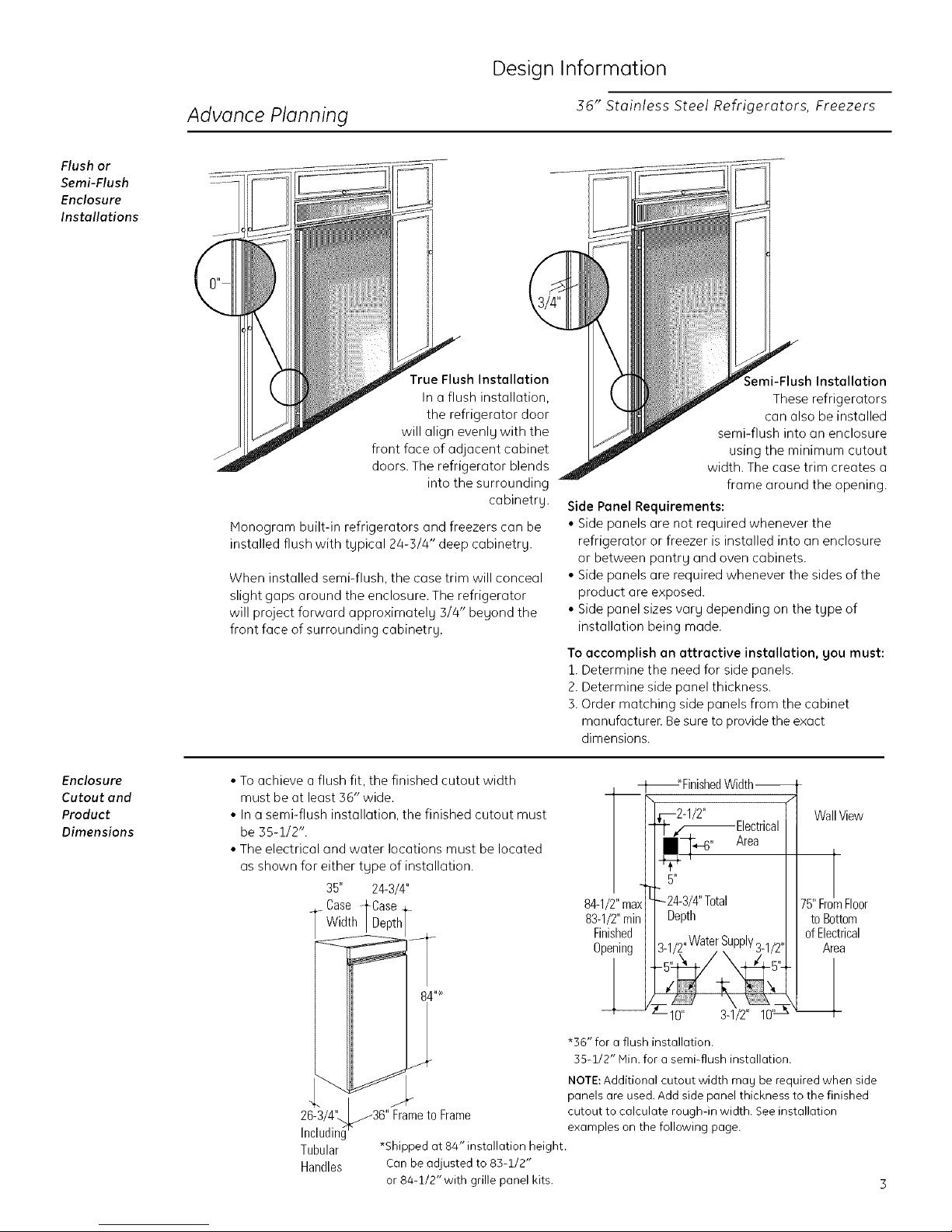
True Flush Installation
In a flush installation,
the refrigerator door
will align evenly with the
front face of adjacent cabinet
doors. The refrigerator blends
into the surrounding
Honogram built-in refrigerators and freezers can be
installed flush with tupical 24-3/4" deep cabinetry.
When installed semi-flush, the case trim will conceal
slight gaps around the enclosure. The refrigerator
will project forward approximatel U 3/4" beyond the
front face of surrounding cabinetry.
cabinetry.
36" Stainless Steel Refrigerators, Freezers
Semi-Flush Installation
These refrigerators
can also be installed
semi-flush into on enclosure
using the minimum cutout
width. The case trim creates o
frame around the opening.
Side Panel Requirements:
• Side panels are not required whenever the
refrigerator or freezer is installed into an enclosure
or between pantry and oven cabinets.
• Side panels are required whenever the sides of the
product are exposed.
• Side panel sizes varg depending on the type of
installation being made.
To accomplish an attractive installation, gou must:
1. Determine the need for side panels.
2. Determine side panel thickness.
S. Order matching side panels from the cabinet
manufacturen Be sure to provide the exact
dimensions.
Enclosure
Cutout and
Product
Dimensions
• To achieve a flush fit, the finished cutout width
must be at least 56" wide.
• In a semi-flush installation, the finished cutout must
be 35-1/2".
• The electrical and water locations must be located
as shown for either type of installation.
26-3/4",..._36" Frameto Frame
Including
Tubular
Handles
35" 24-3/4"
Case _LCase
Width/Depth
*Shipped Qt 84" installation height.
Can be odjusted to 83-1/2"
or 84-1/2"with grille panel kits.
_Finished Width-
,_--2-1/2" [] Wall View
_- ,f_Electrical
II1- Area
I
84-1/2" max
83-1/2" rain
Finished
Opening
84 "e
j 55-1/2" Hin. for a semi-flush installation.
£
*36" for a flush installation.
NOTE: Additional cutout width may be required when side
panels are used. Add side panel thickness to the finished
cutout to calculate rough-in width. Seeinstallation
examples on the following page.
-M'
5"
_-24-3/4" Total II 75" FromFloor
Depth I I to Bottom
-5'z_-/3-1/2"Water Supply3-1/2X'L_L 5" t! Area
-10" 3-1/2" 10'
./1
II
II of Electrical
iN_
Design Information
36" Stoinless Steel Refrigerotors, Freezers
Side By Side
Installation
Of Freezer
And Refrigerator
84-1/2"max
83-1/2"rain
Finished
Opening
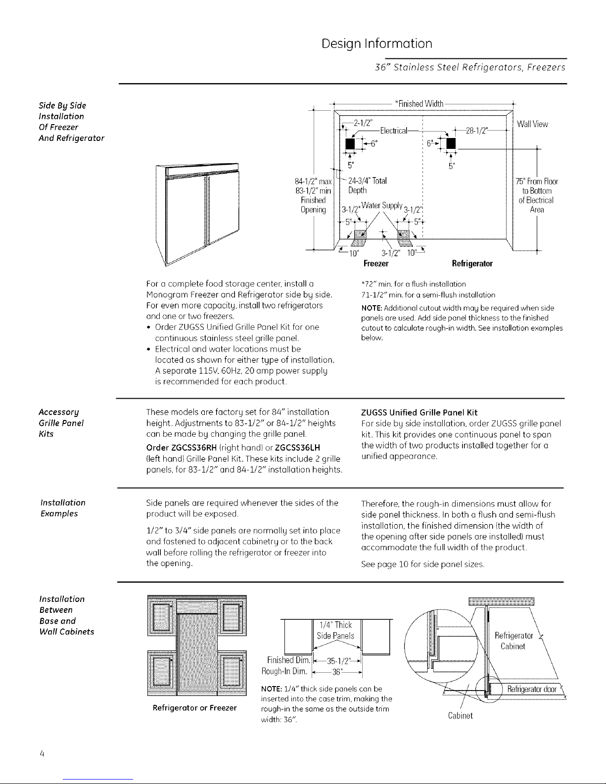
For a complete food storage centec install a
Monogram Freezer and Refrigerator side bg side.
For even more capacitg, install two refrigerators
and one or two freezers.
• Order ZUGSS Unified Grille Panel Kit for one
continuous stainless steel grille panel.
• Electrical and water locations must be
located as shown for either tgpe of installation.
A separate 115V, 60Hz, 20 amp power supplg
is recommended for each product.
t *FinishedWidth
5"
24-3/4" Total
Depth
5"
Freezer Refrigerator
*72" min. for a flush installation
71-1/2" min. for a semi-flush installation
NOTE:Additional cutout width ma Nbe required when side
panels are used. Add side panel thickness to the finished
cutout to calculate rough-in width. See installation examples
below.
WallView
75"FromFloor
toBottom
ofElectrical
Area
Accessory
Grille Panel
Kits
Installation
Examples
Installation
Between
Base and
Wall Cabinets
These models are factorg set for 84" installation
height. Adjustments to 85-1/2" or 84-1/2" heights
can be made bg changing the grille panel.
Order ZGCSS36RH(right hand) or ZGCSS36LH
(left hand) Grille Panel Kit.These kits include 2 grille
panels, for 83-1/2" and 84-1/2" installation heights.
Side panels are required whenever the sides of the
product will be exposed.
1/2" to 3/4" side panels are normallg set into place
and fastened to adjacent cabinetrg or to the back
wall before rolling the refrigerator or freezer into
the opening.
I II1/4"ThickII I
FinishedDim_3.5-1/2' 1
Rough-In Dim. _36'_ I
NOTE: 1/4"thick side panels can be
Refrigerator or Freezer
inserted into the case trim, making the
rough-in the same as the outside trim
width: 56".
ZUGSS Unified Grille Panel Kit
For side bg side installation, order ZUGSS grille panel
kit. This kit provides one continuous panel to span
the width of two products installed together for a
unified appearance.
Therefore, the rough-in dimensions must allow for
side panel thickness. In both a flush and semi-flush
installation, the finished dimension (the width of
the opening after side panels are installed) must
accommodate the full width of the product.
See page 10 for side panel sizes.
liiiii
Refrigerat0r_
Refrigerator door _
Cabinet
Design Information
36" Stoinless Steel Refrigerotors, Freezers
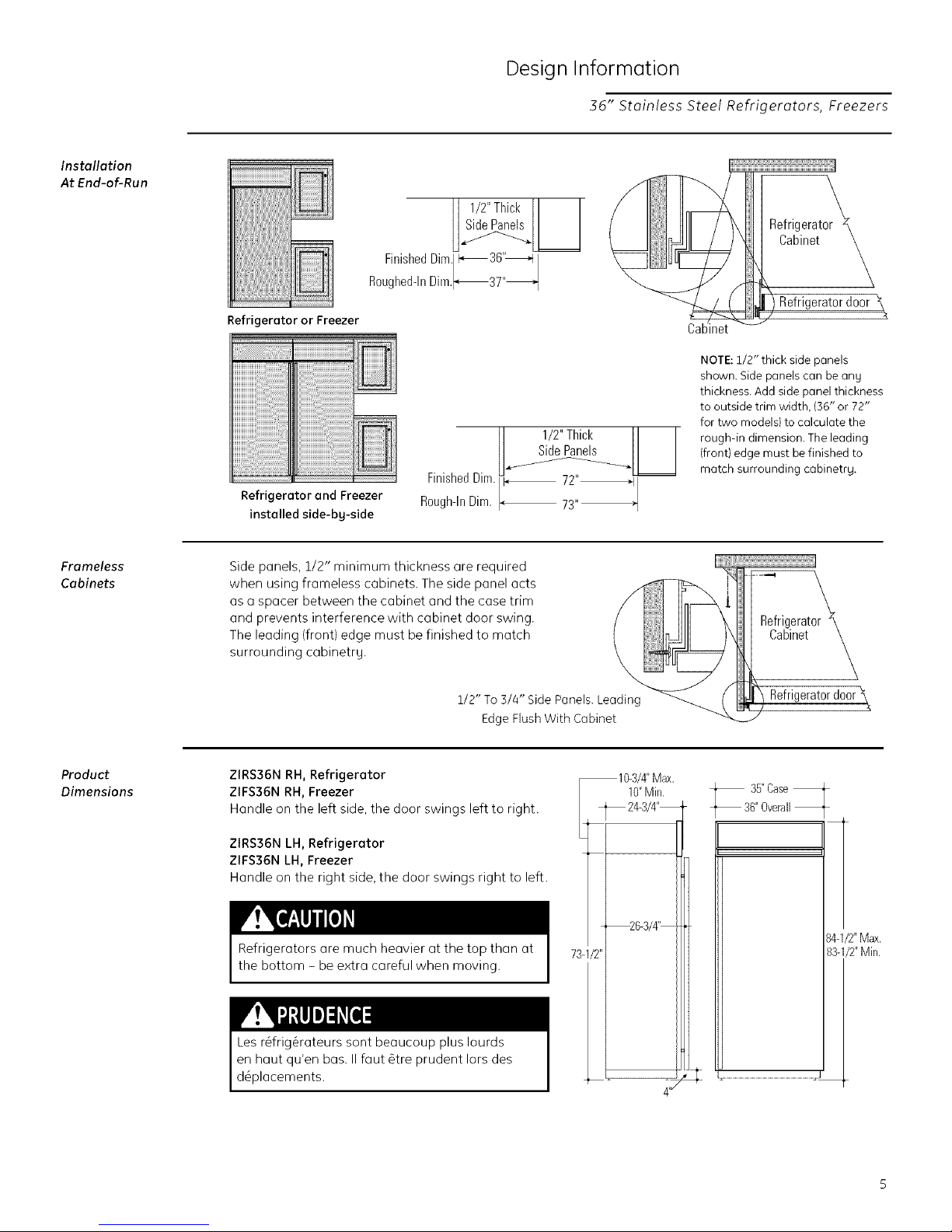
Installation
At End-of-Run
Frameless
Cabinets
I I
H 1/2" Thick II I
Finished
Rougheddn Dim._37"_
Refrigerator or Freezer
II 1/2"Thick II I
SidePanels
Refrigerator and Freezer
installed side-bg-side
Side panels, 1/2" minimum thickness are required --_
FinishedDim.i_ _
Rough-InDim.
CaL
NOTE: 1/2" thick side panels
shown. Side panels can be ang
thickness. Add side panel thickness
to outside trim width, (36" or 72"
for two models) to calculate the
rough-in dimension. The leading
(front) edge must be finished to
match surrounding cabinetrg.
Refrigerator_
Cabinet k
/ Refrigeratordoor
Product
Dimensions
and prevents interference with cabinet door swing. Refrigerat
The leading (front) edge must be finished to match Cabinet
surrounding cabinetry.
when using frameless cabinets. The side panel acts _ _ k
1/2" To 3/4" Side Panels. he _ Refrigerator door \
Edge Flush With Cabinet _
ZIRS36N RH, Refrigerator
ZIFS36N RH, Freezer
Handle on the left side, the door swings left to right.
ZIRS36N LH, Refrigerator
ZIFS36N LH, Freezer
Handle on the right side, the door swings right to left.
Refrigerators are much heavier at the top than at
73 /2"
10-3/4"Max.
10"Min.
_ 24-3/4"--
_6-3/4'--
35"Casef
36"Overall
the bottom - be extra careful when moving.
Les r_frig_rateurs sont beaucoup plus Iourds
en haut qu'en bas. II faut &tre prudent Iors des
d_placements.
84-1/2"Max.
83-1/2"Min.
Installation Preparation
36" Stainless Steel Refrigerators, Freezers
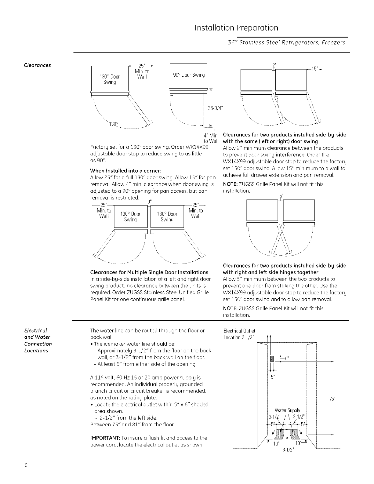
Clearances
130° Door Wall
Swing
Min. to
""130 ° "_{':')
, 90° Door Swing
[__
i,
'\\
....... --1 ,"._
,.
J i36-3/4"
4"_Min.
to Wall
Factory set for a 130° door swing. Order WX14X99
adjustable door stop to reduce swing to as little
as 90 °.
When Installed into a corner:
Allow 25" for a full 130 ° door swing. Allow 15" for pan
removal. Allow 4" min. clearance when door swing is
adjusted to a 90 ° opening for pan access, but pan
removal is restricted.
25 _'_
Min. to 130° Door 130° Door
--25" H
Wa Swing Swing
,,1 I I
// 1-' '-r
:::!:::::i::x ,,"
"--. ........ j/j
Clearances for Multiple Single Door Installations
In a side-by-side installation of a left and right door
swing product, no clearance between the units is
required. Order ZUGSS Stainless Steel Unified Grille
Panel Kit for one continuous grille panel.
,/
Min. to
Wall
[,,
2"
H _15'%
•)\ ! J\
• ','-[ \\ '\
\\
, \\ %
"'.. .;,_: "-.. .;,,_
Clearances for two products installed side-by-side
with the same (left or right) door swing
Allow 2" minimum clearance between the products
to prevent door swing interference. Order the
WX14X99 adjustable door stop to reduce the factory
set 150 ° door swing. Allow 15" minimum to a wall to
achieve full drawer extension and pan removal.
NOTE: ZUGSS Grille Panel Kit will not fit this
installation.
! '\/' !
'-i \v:':,i' ]"
'_ , //'// \,'\\, jJ
Clearances for two products installed side-by-side
with right and left side hinges together
Allow 5" minimum between the two products to
prevent one door from striking the othen Use the
WX14X99 adjustable door stop to reduce the factory
set 130 ° door swing and to allow pan removal.
NOTE: ZUGSS Grille Panel Kit will not fit this
installation.
5"
A A /
////'\ \ /
/ / \ ',, /
\\
\,'\
Electrical
end Water
Connection
Locations
The water line can be routed through the floor or
back wall.
• The icemaker water line should be:
- Approximately 3-1/2" from the floor on the back
wall, or 3-1/2" from the back wall on the floon
- At least 5" from either side of the opening.
A 115 volt, 60 Hz 15 or 20 amp power supply is
recommended. An individual properly grounded
branch circuit or circuit breaker is recommended,
as noted on the rating plate.
• Locate the electrical outlet within 5" x 6" shaded
area shown.
- 2-1/2" from the left side.
Between 75" and 81" from the floon
IMPORTANT: To insure a flush fit and access to the
power cord, locate the electrical outlet as shown.
Electrical Outlet
Location 2-1/2"
y6I
75"
Water Supply |
3-1/2" / \ 3-1/2"|
3-1/2"
 Loading...