

Page 1
SECTION 1
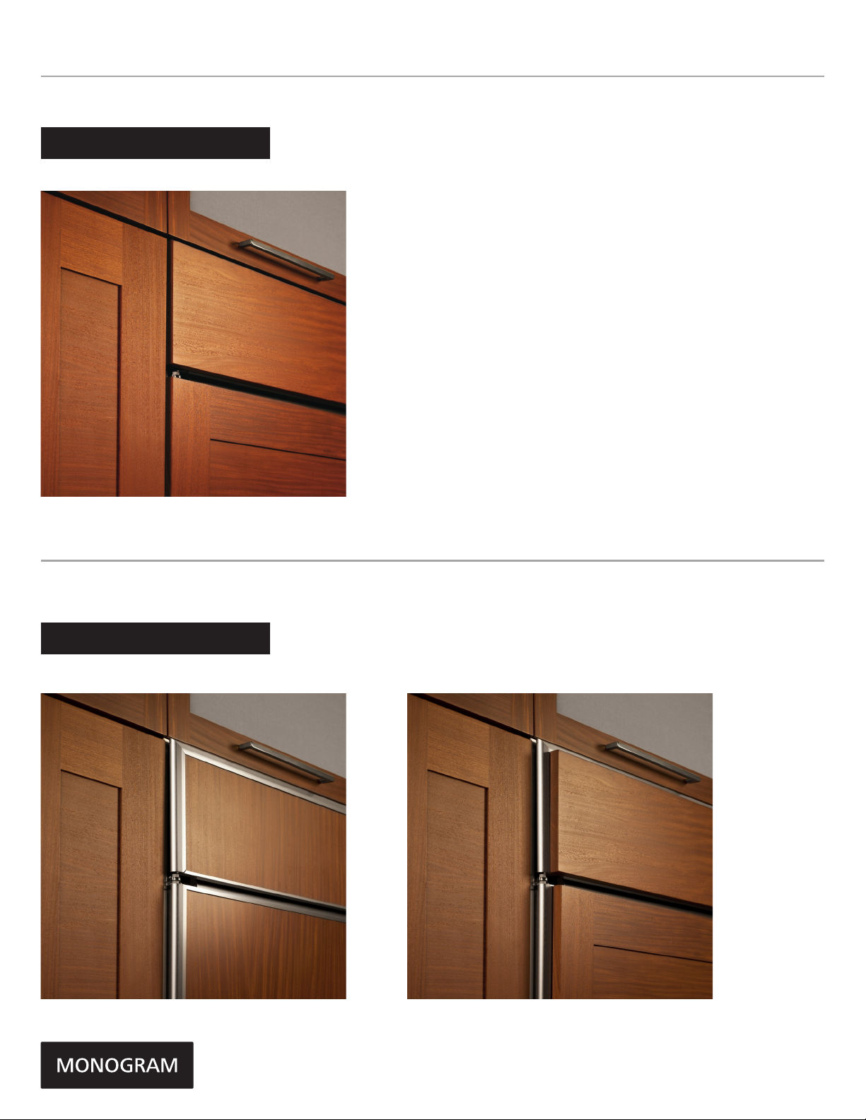
FLUSH INSET INSTALLATION
ZIF360NHLHMonogram 36" Built-In All-Freezer
ZIF360NHLHMonogram 36" Built-In All-Freezer
SECTION 2
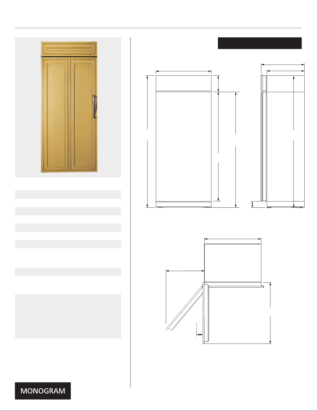
STANDARD INSTALLATION
1/4" FRAMED PANELS 3/4" OVERLAY PANELS
Product Specification Revised 5/16
Page 2
ZIF360NHLHMonogram 36" Built-In All-Freezer
ZIF360NHLHMonogram 36" Built-In All-Freezer
SPECIFICATIONS
Overall Width 38" (96.5 cm)
Overall Height 84 11/16" (215.1 cm)
Overall Depth 26 1/8" (66.3 cm)
Door Clearance 38 3/4" (98.4 cm)
Cutout Width 39" (99.1 cm)
Cutout Height 85" (215.9 cm)
Cutout Depth 26 3/16" (66.5 cm)
Plumbing Requirements 1/4" OD copper
tubing or GE
SmartConnect kit
Shipping Weight 570 lb (258.5 kg)
†
†
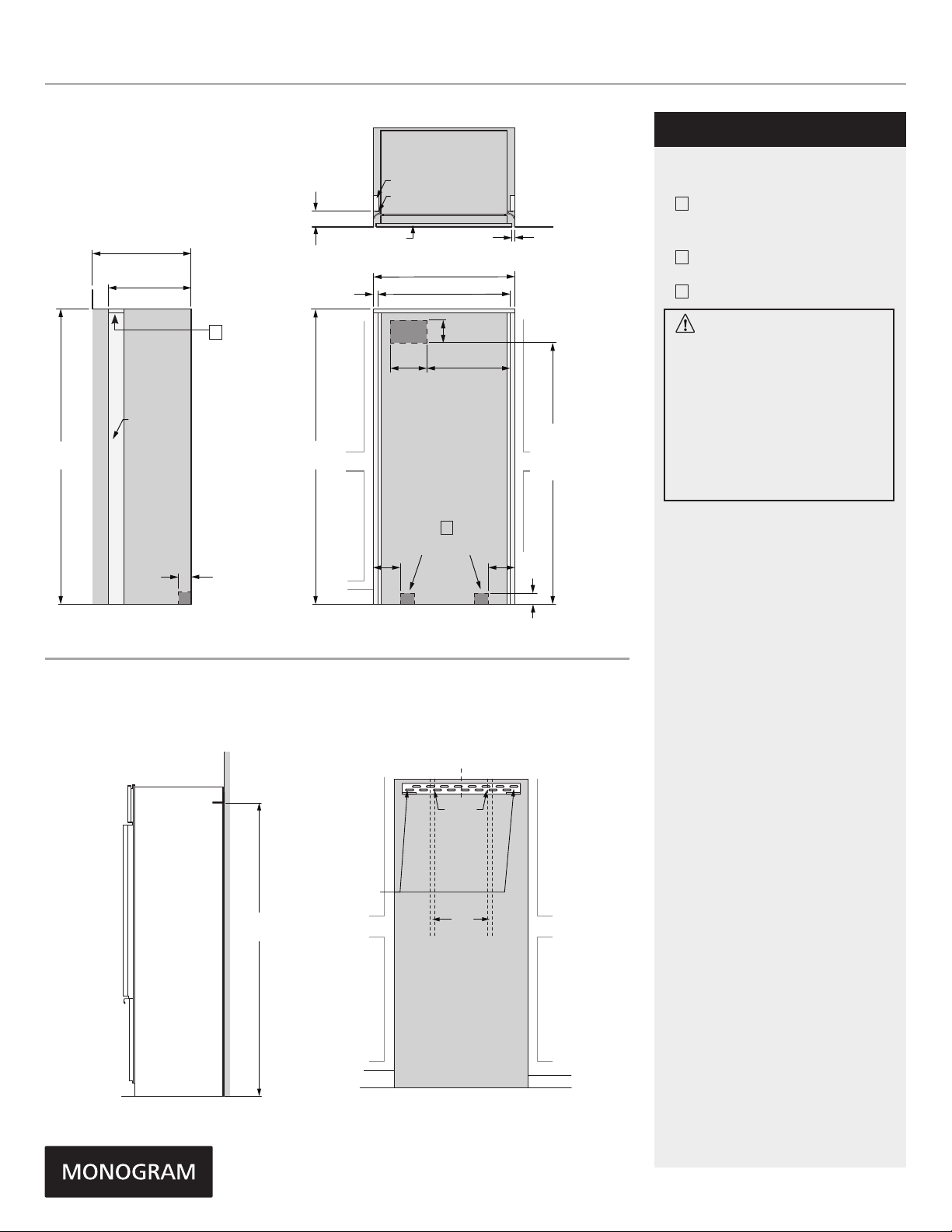
OVERALL DIMENSIONS
FLUSH INSET INSTALLATION
26 1/8" (66.3)
38" (96.5)
10 15/16"
(27.8)
*84 11/16"
(215.1)
69 3/4"
†
FRONT VIEW
* Shipping height . Use leveling legs and wheels for maximum 1" height
adjustment from shipping height. Nominal installation height is 84 11/16".
Allow
15" (38.1) min
clearance for 115˚
door swing
(177.2)
*73 3/4"
(187.3)
35" (89.0)
Case width
*4"
(10.2)
20 5/8" (52.4)
* 84"
(213.4)
SIDE VIEW
† Dimensions include 3/4" custom cabinet panel
ATTENTION ELECTRICIAN:
A 115 volt 60Hz., 15 or 20 amp power supply
is required. An individual properly grounded
branch circuit or circuit breaker is recommended.
Install a properly grounded 3-prong electrical
receptacle recessed into the back wall.
TOP VIEW
Allow 4" (10.2) min
clearance to a wall
for 90˚ door swing
Dimensions in parentheses are in centimeters unless otherwise noted.
Actual product dimensions may vary due to manufacturing tolerances.
Product Specification Revised 5/16
38 3/4"
(98.4)
Page 3
FLUSH INSET INSTALLATION 3/4" PANELS
24" (61.0)
1 1/2"
(3.8)
3"
(7.6)
7/16"
(1.1)
Trim overlap
35 1/2" (90.2)
2 5/16"
(5.9)
SIDE VIEWFRONT VIEW
*83 1/2" min
*84 1/2" max
(212.1-214.6)
*Trim will overlap
additional 7/16"
3 1/2"
(8.9)
75"
(190.5 )
From floor
to bottom
of electrical
area
ELEC.
6"
(15.2)
10"
(25.4)
WATER
5"
(12.7)
5"
(12.7)
3 1/2"
(9.0)
WATER
10" (25.4)
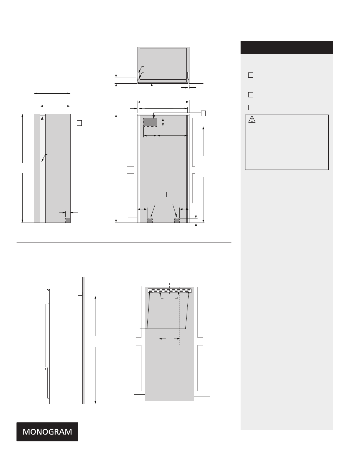
FLUSH INSET INSTALLATION 3/4" PANELS
5 1/4" (13.3)
26 3/16" (66.5)
Flush inset depth
20 15/16" (53.2)
Depth to cleat
3/4" (1.9)
Width of side cleats
TOP VIEW
Case
Finished cleats
Case Trim
Door
3/4" Panel
39" (99.1) Flush inset width
37 1/2" (95.3)
Width between cleats
1/2" (1.3)
ZIF360NHLHMonogram 36" Built-In All-Freezer
ZIF360NHLHMonogram 36" Built-In All-Freezer
FLUSH INSET INSTALLATION
NOTES
A
Mounting the junction box in this
location will also allow for front
accessibility through access panel.
B
Water supply area.
C
Top cleat should be 1" thick
NOTES
85"
(215.9)
ANTI-TIP BRACKET
Finished cleats
5 1/2"
(14.0)
24 3/16"
9"
(61.4)
ELEC.
(22.9)
C
WARNING:
The freezer is top heavy and must be
secured to prevent the possibility of
tipping forward. Failure to do so may
result in death or serious injury.
The information below is for cabinet
design only. When installing the
anti-tip system you must use the
product installation instructions.
The information below applies to all
85"
(215.9)
75 1/2"
(191.8 )
From floor
to bottom
of electrical
area
installation constructions:
• A wall bracket, bolts and toggles will
B
WATER
3 1/2"
(9.0)
7"
(17.8)
3 1/2"
(8.9)
3 1/2"
(8.9)
7"
(17.8)
W
FRONT VIEWSIDE VIEW
be supplied with the unit.
• The bolts will be used to attach
bracket to wall in 4 locations. Two
of the locations must penetrate the
center of the wall studs.
• The toggles are used for stability in
drywall and when metal studs are
encountered. Lag bolts are used in
wood studs.
• In installation opening, measure 82"
from floor and draw a horizontal line.
• Locate and mark the wall studs on
horizontal line. Verify at least two
studs have their centerlines within
the center 32.5" of installation
opening to ensure 2 wall studs are
penetrated.
• The bracket will be centered left
to right in opening with bottom of
bracket on the horizontal line.
• When unit is placed in opening, the
bracket tabs will align with openings
in back of the unit. The unit will be
secured to the bracket using supplied
“L” bolts.
See Installation Instructions for
detailed instructions.
81 1/2"
(207.0)
Use two
additional hole
locations at end
of brackets
C
L
Bracket
mounted
into vertical
wall studs
centered
within the
cutout
Ensure holes
selected are
centered on
the studs
Wall
Studs
SIDE VIEW INSTALLED
WITH ANTI-TIP BRACKET
FRONT VIEW OF CUTOUT
WITH ANTI-TIP BRACKET
Product Specification Revised 5/16
Page 4
ZIF360NHLHMonogram 36" Built-In All-Freezer
ZIF360NHLHMonogram 36" Built-In All-Freezer
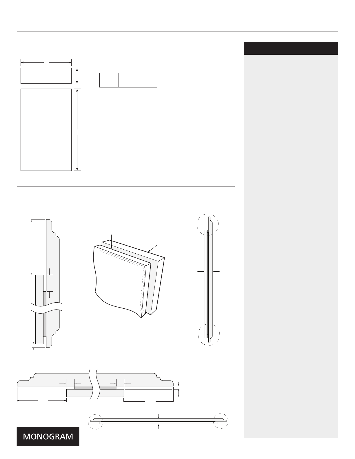
FLUSH INSET 3/4" PANEL DIMENSIONS SINGLE INSTALLATION
A
Grille Panel
Door
Panel
B
C
PANEL DIMENSIONS
A B C
38" 10 7/16" 69 3/4"
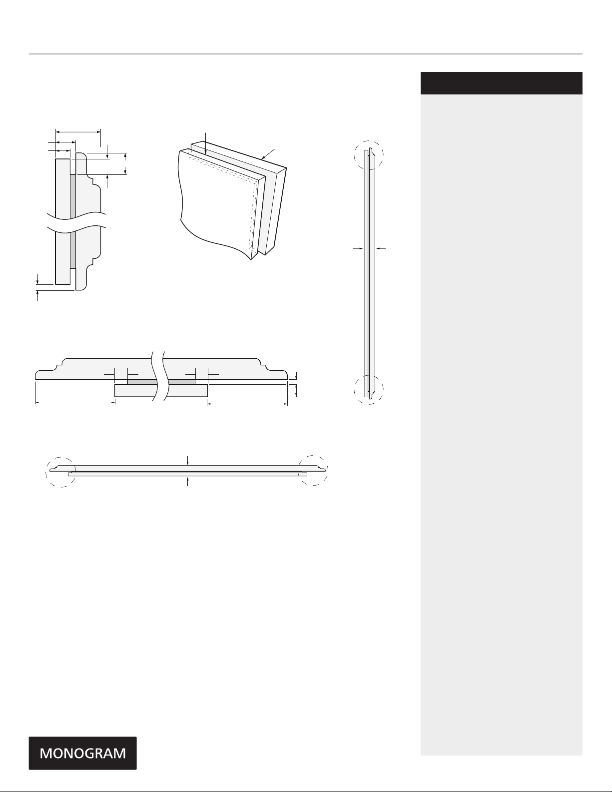
3/4" GRILLE DOOR PANEL ROUTING
DETAIL TOP
NOTE: Routed areas should be
finished as they may be visible
when assembled.
ROUTER DEPTH 1/4"
1-7/16"
Front
TOP
FLUSH INSET INSTALLATION
NOTES
Trimmed freezers are designed to be
customized with decorative panels.
Field-installed 1/2" or 3/4" custom door
and grille panels are required. For 3/4"
raised panels, routing is required. The
router depth is 1/4" all the way around
the panel’s backs. Additional panel width
reductions are required per the diagrams
shown. This will create “picture frame’
routing allowing the panels to slide into
the attached door and grille trims.
Maximum total panel weight:
• Door panel – 67 lbs.
• Grille panel – 11 lbs
Note: For panels constructed with rails
and stiles (5-panel), the rails must be a
minimum of 3" wide and stiles must be a
minimum of 4" wide.
Door Handles
Custom handles are required for flush
installation.
ZKHPSS1: Professional stainless steel
handle designed to fit 3/4" custom panels.
Kit includes one handle – 30 1/2" long.
ZKHSS2: European tubular stainless steel
handle designed to fit 3/4" panels. Kit
includes one handle – 64 1/4" long.
Order ZUG2: Unified grille kit for
dual installation. Maximum total panel
weight - 25 lbs.
Back
CORNER VIEW SHOWING
“PICTURE FRAME” ROUTING
1/8"
DETAIL BOTTOM
DETAIL
LEFT SIDE
ROUTER DEPTH 1/4" ROUTER DEPTH 1/4"
2-1/16"
LEFT
SIDE
DETAIL RIGHT
SIDE
2-1/16"
Front
Back
3/4" PANEL BOTTOM VIEW
(AFTER ROUTING)
BOTTOM
3/4" PANEL SIDE VIEW
(AFTER ROUTING)
3/32"
1/4"
FrontBack
RIGHT
SIDE
Product Specification Revised 5/16
Page 5
ZIF360NHLHMonogram 36" Built-In All-Freezer
TOP
3/4" RAISED DOOR PANEL ROUTING
DETAIL TOP
3/4"
11/32"
1/4"
7/16"
1/4"
3/16"
DETAIL BOTTOM
DETAIL
LEFT SIDE
ROUTER DEPTH 1/4" ROUTER DEPTH 1/4"
2-1/16"
NOTE: Routed areas should be
finished as they may be visible
when assembled.
Back
CORNER VIEW SHOWING
“PICTURE FRAME” ROUTING
DETAIL RIGHT
2-1/16"
SIDE
Front
3/32"
1/4"
FrontBack
BOTTOM
3/4" PANEL SIDE VIEW
(AFTER ROUTING)
FLUSH INSET INSTALLATION
NOTES
Trimmed freezers are designed to be
customized with decorative panels.
Field-installed 1/2" or 3/4" custom door
and grille panels are required. For 3/4"
raised panels, routing is required. The
router depth is 1/4" all the way around
the panel’s backs. Additional panel width
reductions are required per the diagrams
shown. This will create “picture frame’
routing allowing the panels to slide into
the attached door and grille trims.
Maximum total panel weight:
• Door panel – 67 lbs.
• Grille panel – 11 lbs
Note: For panels constructed with rails
and stiles (5-panel), the rails must be a
minimum of 3" wide and stiles must be a
minimum of 4" wide.
Door Handles
Custom handles are required for flush
installation.
ZKHPSS1: Professional stainless steel
handle designed to fit 3/4" custom panels.
Kit includes one handle – 30 1/2" long.
ZKHSS2: European tubular stainless steel
handle designed to fit 3/4" panels. Kit
includes one handle – 64 1/4" long.
Order ZUG2: Unified grille kit for
dual installation. Maximum total panel
weight - 25 lbs.
LEFT
SIDE
Front
Back
3/4" PANEL BOTTOM VIEW
(AFTER ROUTING)
RIGHT
SIDE
Product Specification Revised 5/16
Page 6
ZIF360NHLHMonogram 36" Built-In All-Freezer
24" (61.0)
1 1/2"
(3.8)
3"
(7.6)
7/16"
(1.1)
Trim overlap
35 1/2" (90.2)
2 5/16"
(5.9)
SIDE VIEWFRONT VIEW
*83 1/2" min
*84 1/2" max
(212.1-214.6)
*Trim will overlap
additional 7/16"
3 1/2"
(8.9)
75"
(190.5 )
From floor
to bottom
of electrical
area
ELEC.
6"
(15.2)
10"
(25.4)
WATER
5"
(12.7)
5"
(12.7)
3 1/2"
(9.0)
WATER
10" (25.4)
FLUSH INSET INSTALLATION 1/2" PANELS
26 3/16" (66.5)
Flush inset depth
20 13/16" (52.9)
Depth to cleat
C
Finished cleats
3 1/2"
(8.9)
85"
(215.9)
W
ANTI-TIP BRACKET
81 1/2"
(207.0)
5 3/8" (13.7)
3/4" (1.9)
Width of side cleats
85"
(215.9)
Use two
additional hole
locations at end
of brackets
TOP VIEW
Case
Finished cleats
Case Trim
Door
1/2" Panel
39" (99.1) Flush inset width
37 1/2" (95.3)
Width between cleats
ELEC.
9"
(22.9)
7"
WATER
(17.8)
3 1/2"
FRONT VIEWSIDE VIEW
5 1/2"
(14.0)
24 3/16"
(61.4)
B
(9.0)
C
L
Bracket
mounted
into vertical
wall studs
centered
within the
cutout
Ensure holes
selected are
centered on
the studs
Wall
Studs
7"
(17.8)
1/2" (1.3)
75 1/2"
(191.8 )
From floor
to bottom
of electrical
3 1/2"
(8.9)
area
FLUSH INSET INSTALLATION
NOTES
A
Mounting the junction box in this
location will also allow for front
accessibility through access panel.
B
Water supply area.
C
A
Top cleat should be 1" thick
WARNING:
The freezer is top heavy and must be
secured to prevent the possibility of
tipping forward. Failure to do so may
result in death or serious injury.
The information below is for cabinet
design only. When installing the
anti-tip system you must use the
product installation instructions.
The information below applies to all
installation constructions:
• A wall bracket, bolts and toggles will
be supplied with the unit.
• The bolts will be used to attach
bracket to wall in 4 locations. Two
of the locations must penetrate the
center of the wall studs.
• The toggles are used for stability in
drywall and when metal studs are
encountered. Lag bolts are used in
wood studs.
• In installation opening, measure 82”
from floor and draw a horizontal line.
• Locate and mark the wall studs on
horizontal line. Verify at least two
studs have their centerlines within the
center 32.5" of installation opening to
ensure 2 wall studs are penetrated.
• The bracket will be centered left
to right in opening with bottom of
bracket on the horizontal line.
• When unit is placed in opening, the
bracket tabs will align with openings
in back of the unit. The unit will be
secured to the bracket using supplied
“L” bolts.
See Installation Instructions for
detailed instructions.
NOTES
SIDE VIEW INSTALLED
WITH ANTI-TIP BRACKET
FRONT VIEW OF CUTOUT
WITH ANTI-TIP BRACKET
Product Specification Revised 5/16
Page 7

ZIF360NHLHMonogram 36" Built-In All-Freezer
FLUSH INSET 1/2" PANEL DIMENSIONS SINGLE INSTALLATION
A
PANEL DIMENSIONS
Grille Panel
Door
Panel
B
1/4" Backer Panel 33 7/8" 8 7/8" 69 5/16"
.10" Space Panel 32 1/2" 7 5/8" 67 15/16"
1/2" Overlay Panel 38" 10 7/16" 69 3/4"
A B C
C
FLUSH INSET INSTALLATION
NOTES
The 1/2" overlay panel must be secured
to a .10" spacer panel and a 1/4" thick
backer panel, which slides into the trim.
Assemble the panels with glue and
screws:
• Center the spacer panel on the backer
panel, left to right and top to bottom.
Secure the panels with glue.
• Refer to the chart for locating the backer
panel to the overlay panel. Secure
the overlay panel to the backer panel
with glue and screws. Screws must be
countersunk into the backer panel
Order ZUG2: Unified grille kit for dual
installation. Maximum total panel
weight – 25 lbs.
Note: For panels constructed with rails
and stiles (5-panel), the rails must be a
minimum of 3" wide and stiles must be a
minimum of 4" wide.
1/2" OUTER PANEL TO BACKER PLACEMENT
C
Hinge Side
Door Panel Back
Backer with
Overlay Panel
Assembly
A
B
D
PANEL DIMENSIONS
A B C D
Door Panel 2 1/16" 2 1/16" 3/16" 1/4"
Grille Panel 2 1/16" 2 1/16" 1 7/16" 1/8"
Door
1/4"
Backer
Panel
Grille Back
C
A B
1/2"
Overlay
Panel
.10"
Spacer
D
Product Specification Revised 5/16
Page 8

ZIF360NHLHMonogram 36" Built-In All-Freezer
DUAL INSTALLATIONS
A
75" (190.5)
5 1/2"
(13.9)
Finished Width
7 1/2"
7 1/2"
(19.1)
ELEC.
9"
(22.9)
(19.1)
24 3/16" (61.4)
5 1/2"
(13.9)
WATER
3 1/2"
(9.0)
7"
(17.8)
75 1/2"
From floor
to bottom
of electrical
3 1/2"
(8.9)
(191.8 )
area
4 5/16"
(10.9)
85"
(215.9)
Finished
Opening
ELEC.
7"
(17.8)
9"
(22.9)
WATER
3 1/2"
(9.0)
FLUSH INSET 1/2" PANEL DIMENSIONS DUAL INSTALLATION
A
Grille Panel
B
26 3/16" (66.5)
Min. Cutout Depth
FLUSH INSET INSTALLATION
NOTES
Trimmed freezers are designed to
be customized with decorative panels.
Field-installed 1/2" or 3/4" custom door,
drawer and grille panels are required.
For 3/4" raised panels, routing is required.
The router depth is 1/4" all the way around
the panel’s backs. Additional panel width
reductions are required per the diagrams
shown. This will create “picture frame’
routing allowing the panels to slide into
the attached door, drawer and grille trims.
Maximum total panel weight:
• Fresh food door panels – 67 lbs.
• Grille panel – 22 lbs
Door Handles
Custom handles are required for flush
installation.
ZKHPSS1: Professional tubular stainless steel
handle designed to fit custom panels. Kit
includes one handle – 30 1/2" long. Order
2 kits from your Monogram supplier.
3 1/2"
(8.9)
W
ZKHCSS2: Custom European handle
designed to fit custom panels. Kit includes 2
handles. Door handle is 44 3/16" and drawer
handle is 33 3/16".
Order ZUG2: Unified grille kit for
dual installation. Maximum total panel
weight - 25 lbs.
ZKHCT: Handle side trim for left-hand and
right-hand door. For use on a custom panel
when using a custom handle.
Order ZUG2: Custom panel unified grille kit
for one continuous grille panel.
D
Door
Panel
D
Door
Panel
PANEL DIMENSIONS
A B C D
1/4" Backer Panel 69 7/8" 8 7/8" 69 5/16" 33 7/8"
.10" Space Panel 68 1/2" 7 5/8" 67 15/16" 32 1/2"
1/2" Overlay Panel 74" 10 7/16" 69 3/4" 36 7/8"
The 1/2" overlay panel must be secured
to a .10" spacer panel and a 1/4" thick
C
backer panel, which slides into the trim.
Assemble the panels with glue and screws:
• Center the spacer panel on the backer
panel, left to right and top to bottom.
Secure the panels with glue.
• Refer to the single unit ush installation
diagram on pg 7 for backer to 1/2" overlay
panel placement.
Order ZUG2: Unified grille kit for dual
installation. Maximum total panel
weight – 25 lbs.
A
A Separate 115V, 60Hz, 15- or 20-amp
power supply is recommended for each
product.
Product Specification Revised 5/16
Page 9

ZIF360NHLHMonogram 36" Built-In All-Freezer
Front
DETAIL BOTTOM
FLUSH INSET 3/4" PANEL DIMENSIONS DUAL INSTALLATION
D
Door
Panel
A
Grille Panel
D
Door
Panel
B
C
PANEL DIMENSIONS
A B C D
74" 10 7/16" 69 3/4" 36 7/8"
3/4" RAISED DOOR PANEL ROUTING - (SEE PAGE 4 FOR 3/4" GRILLE
PANEL ROUTING DIAGRAMS)
DETAIL TOP
NOTE: Routed areas should be
finished as they may be visible
when assembled.
Front
Back
11/32"
1/4"
3/4"
1/4"
7/16"
TOP
FLUSH INSET INSTALLATION
NOTES
Trimmed freezers are designed to
be customized with decorative panels.
Field-installed 1/2" or 3/4" custom door,
drawer and grille panels are required.
For 3/4" raised panels, routing is required.
The router depth is 1/4" all the way around
the panel’s backs. Additional panel width
reductions are required per the diagrams
shown. This will create “picture frame’
routing allowing the panels to slide into
the attached door, drawer and grille trims.
Maximum total panel weight:
• Fresh food door panels – 67 lbs.
• Grille panel – 22 lbs
Door Handles
Custom handles are required for flush
installation.
ZKHPSS1: Professional tubular stainless steel
handle designed to fit custom panels. Kit
includes one handle – 30 1/2" long. Order
2 kits from your Monogram supplier.
ZKHCSS2: Custom European handle
designed to fit custom panels. Kit includes 2
handles. Door handle is 44 3/16" and drawer
handle is 33 3/16".
Order ZUG2: Unified grille kit for
dual installation. Maximum total panel
weight - 25 lbs.
ZKHCT: Handle side trim for left-hand and
right-hand door. For use on a custom panel
when using a custom handle.
Order ZUG2: Custom panel unified grille kit
for one continuous grille panel.
3/16"
DETAIL HINGE
SIDE
HINGE
SIDE
ROUTER DEPTH 1/4"
2 1/16"
3/4" PANEL BOTTOM VIEW
(AFTER ROUTING)
FrontBack
CORNER VIEW SHOWING
“PICTURE FRAME” ROUTING
DETAIL HANDLE
SIDE
3/16"
HANDLE
SIDE
Back
BOTTOM
3/4" PANEL SIDE VIEW
(AFTER ROUTING)
Product Specification Revised 5/16
Page 10

ZIF360NHLHMonogram 36" Built-In All-Freezer
DUAL PRODUCT CLEARANCES
15" (38.1) min
To wall
115˚
Door swing
1"
(2.5)
A
115˚
Door swing
15" (38.1) min
To wall
FLUSH INSET INSTALLATION
NOTES
A
In a side-by-side installation of a left-
and-right-hand door swing product,
1" clearance between the units is
required.
Product Specification Revised 5/16
Page 11

ZIF360NHLHMonogram 36" Built-In All-Freezer
ZIF360NHLHMonogram 36" Built-In All-Freezer
SPECIFICATIONS
Overall Width 36" (91.4 cm)
Overall Height 84" (213.4 cm)
Overall Depth 25 3/8" (64.45 cm)
Door Clearance 36 3/4" (93.4 cm)
Cutout Width 35 1/2" (90.2 cm)
Cutout Height 83 1/2" - 84 1/2"
(212.1 - 214.6 cm)
Cutout Depth 24" (61 cm)
Plumbing Requirements 1/4" OD copper
tubing or GE
SmartConnect kit
Shipping Weight 569 lb
OVERALL DIMENSIONS
STANDARD INSTALLATION
36" (91.5)
*84"
(213.4)
*73 1/4"
69 5/8"
(176.8)
* Shipping height . Use leveling legs and wheels for maximum
1" height adjustment from shipping height.
** Allow 25" (63.5) min
clearance for 130˚
door swing
*3"
(7.6)
35" (89.0)
Case width
(186.1)
1 7/8"
(4.8)
*3 1/4"
(8.3)
25 1/8" (63.8)
23 7/8" (60.7)
*83 1/2"
(212.1)
SIDE VIEWFRONT VIEW
ATTENTION ELECTRICIAN:
A 115 volt 60Hz., 15 or 20 amp power supply
is required. An individual properly grounded
branch circuit or circuit breaker is recommended.
Install a properly grounded 3-prong electrical
receptacle recessed into the back wall.
36 3/4"
TOP VIEW
** Allow 4" (10.2) min
clearance to a wall
for 90˚ door swing
**These units are equipped with a 3-position door stop. The factory set 130° door swing can
be adjusted to 90° or 130° for standard installation if clearance to adjacent cabinets or
walls is restricted. Allow 15" minimum clearance to wall for pan removal. If the 90˚ door
stop position is used, pan access is maintained but pan removal is restricted.
Dimensions in parentheses are in centimeters unless otherwise noted.
Actual product dimension may vary due to manufacturing tolerances.
Product Specification Revised 5/16
(93.4)
Page 12

ZIF360NHLHMonogram 36" Built-In All-Freezer
SIDE VIEW
W
25 3/8" (64.5)
1 1/2"
(3.8)
3 1/8"
(7.9)
7/16"
(1.1)
Trim overlap
3 1/2"
(8.9)
FRONT VIEW
ELEC.
35 1/2" (90.2)
2 5/16"
(5.9)
3 1/2"
(8.9)
75
1/2
"
(191.8)
From floor
to bottom
of electrical
area
5 1/2"
(14.0)
9"
(22.9)
5"
(12.7)
5"
(12.7)
WATER
3 1/2"
(9.0)
ZIF360NHLHMonogram 36" Built-In All-Freezer
STANDARD INSTALLATION
2 5/16"
(5.9)
*83 1/2" min
*84 1/2" max
(212.1-214.6)
*Trim will overlap
additional 7/16"
ANTI-TIP BRACKET
ELEC.
9"
(22.9)
5"
(12.7)
FRONT VIEW
35 1/2" (90.2)
5 1/2"
(14.0)
B
WATER
3 1/2"
(9.0)
81 1/2"
(207.0)
5"
(12.7)
3 1/2"
A
75
1/2
(191.8)
From floor
to bottom
of electrical
area
(8.9)
additional hole
locations at end
of brackets
"
Use two
3 1/8"
(7.9)
25 3/8" (64.5)
1 1/2"
SIDE VIEW
C
L
Bracket
mounted
into vertical
wall studs
centered
within the
cutout
Ensure holes
selected are
centered on
the studs
Wall
Studs
(3.8)
STANDARD INSTALLATION
7/16"
(1.1)
Trim overlap
3 1/2"
(8.9)
W
NOTES
A
Mounting the junction box in this
location will also allow for front
accessibility through access
panel.
B
Water supply area.
WARNING:
The freezer is top heavy and must be
secured to prevent the possibility of
tipping forward. Failure to do so may
result in death or serious injury.
The information below is for cabinet
design only. When installing the
anti-tip system you must use the
product installation instructions.
The information below applies to all
installation constructions:
• A wall bracket, bolts and toggles
will be supplied with the unit.
• The bolts will be used to attach
bracket to wall in 4 locations. Two
of the locations must penetrate the
center of the wall studs.
• The toggles are used for stability in
drywall and when metal studs are
encountered. Lag bolts are used in
wood studs.
• In installation opening, measure 81
1/2" from
floor and draw a horizontal line.
• Locate and mark the wall studs on
horizontal line. Verify at least two
studs have their centerlines within
the center 32.5" of installation
opening to ensure 2 wall studs are
penetrated.
• The bracket will be centered left
to right in opening with bottom of
bracket on the horizontal line.
• When unit is placed in opening,
the bracket tabs will align with
openings in back of the unit. The
unit will be secured to the bracket
using supplied “L” bolts.
See Installation Instructions for
detailed instructions.
SIDE VIEW INSTALLED
WITH ANTI-TIP BRACKET
FRONT VIEW OF CUTOUT
WITH ANTI-TIP BRACKET
Product Specification Revised 5/16
Page 13

ZIF360NHLHMonogram 36" Built-In All-Freezer
A
1/4" Framed Panel
ZIF360NHLHMonogram 36" Built-In All-Freezer
STANDARD 1/4" FRAMED PANEL DIMENSIONS SINGLE INSTALLATION
PANEL ASSEMBLY CROSS SECTION
Grille Panel
Door
Panel
B
C
Trim
Door
Supplied Handles
PANEL DIMENSIONS
A B C
1/4" Framed Panel
33 7/8" 8 7/8" 69 5/16"
STANDARD INSTALLATION
NOTES
Trimmed freezers are designed to be
customized with decorative panels.
Field-installed custom door and grille
panels are required.
1/4" Framed Panels:
For 1/4" thick custom panels ordered from
your cabinet maker. The decorative panels
slide into the trim.
Maximum total panel weight:
• Door panel – 67 lbs.
• Grille panel – 11 lbs
STANDARD 3/4" OVERLAY PANEL DIMENSIONS SINGLE INSTALLATION
PANEL ASSEMBLY CROSS SECTION
Trim
1/4" Backer Panel
.10" Spacer Panel
Door
3/4" Overlay Panel
Supplied Handles
PANEL DIMENSIONS
A B C
1/4" Backer Panel
.10" Spacer Panel
3/4" Overlay Panel
.25" + .10" + .75" = 1.10" Total Panel Thickness
33 7/8" 8 7/8" 69 5/16"
32 1/2" 7 5/8" 67 15/16"
34 1/8" 9" 69 9/16"
Grille Panel
A
Door
Panel
B
C
3/4” Overlay Panels:
For 3/4" thick custom panels ordered from
your cabinet maker. The decorative panels
slide into the trim. The overlay panel must be
secured to a 1/4"-thick backer panel which
slides into the trim. A spacer panel 0.10" thick
must be placed between the overlay and
backer panels.
Center each panel over the other. Assemble
the panels with glue and screws. Screws must
be countersunk into the backer panel.
NOTE: Left-to-right offset is not always equal
to top-to-bottom offset.
Maximum total panel weight:
• Door panel – 67 lbs.
• Grille panel – 11 lbs
Door Handles:
The supplied handles can be adjusted to
accommodate both framed or overlay panels.
Custom handles of your choice, supplied by
your cabinet maker, can also be installed.
ZKHPSS1: Professional stainless steel handle
designed to fit 3/4" overlay panels.
Kits include one handle - 30 1/2" long.
ZKHSS2: European tubular stainless steel
handle designed to fit 3/4" overlay panels.
Kits include one handle - 64 1/4" long.
Product Specification Revised 5/16
Page 14

ZIF360NHLHMonogram 36" Built-In All-Freezer
CUSTOM SIDE PANELS
F
24" (61.0)
3/16"
(.5)
1 7/8"
(4.8)
*3" - 4"
(7.6 - 10.2)
*Depending
on installation
height
*84”
*84"
(213.4)
(213.4)
*Depending
*Depending
on installation
on installation
height
STANDARD INSTALLATION
NOTES
F
Side panels must be used whenever
the sides of the freezer will be
exposed. The 1/4" side panels will slip
into the side case trim. Secure the
panels to the freezer with stick-on
hook and loop fastener strips. Order
the side panels from the cabinet
manufacturer.
2 9/16"
(6.5)
Product Specification Revised 5/16
Page 15

ZIF360NHLHMonogram 36" Built-In All-Freezer
1/4" Framed Panel
Supplied Handles
ZIF360NHLHMonogram 36" Built-In All-Freezer
DUAL INSTALLATIONS
4 5/16"
(11.0)
9"
5 1/2"
WATER
3 1/2"
(9.0)
85" (215.9)
Finished
Opening
5"
(12.7)
ELEC.
(22.9)
A
71 1/2" (181.7)
Finished Width
(13.9)
(12.7)5"(12.7)
FRONT VIEW
STANDARD INSTALLATION
26 3/16" (66.5)
24 3/16" (61.4)
9"
5 1/2"
WATER
3 1/2"
(9.0)
(13.9)
5"
(12.7)
75 1/2"
From floor
to bottom
of electrical
3 1/2"
(8.9)
(191.8 )
area
ELEC.
(22.9)
5"
Min. Cutout Depth
3 1/2"
(8.9)
W
SIDE VIEW
NOTES
A
A separate 115V, 60Hz, 15- or 20-amp
power supply is recommended for each
product.
Additional cutout width may be required when
side panels are used.
STANDARD 1/4" FRAMED PANEL DIMENSIONS DUAL INSTALLATION
Grille Panel
D
Door
Panel
PANEL ASSEMBLY
CROSS SECTION
A
B
D
Door
C
Panel
Trim
Door
PANEL DIMENSIONS
A
B
C
D
1/4"
Framed
Panel
69 7/8"
8 7/8"
69 5/16"
33 7/8"
Trimmed freezers are designed to be
customized with decorative panels. Fieldinstalled custom door and grille panels are
required.
1/4" Framed Panels:
For 1/4" thick custom panels ordered from
your cabinet maker. The decorative panels
slide into the trim.
Maximum total panel weight:
• Door panel – 67 lbs.
• Grille panel – 25 lbs
Order ZUG2: Unified grille kit for dual
installation. Maximum total panel weight -
25 lbs.
Product Specification Revised 5/16
Page 16

ZIF360NHLHMonogram 36" Built-In All-Freezer
71 1/2" (181.6)
Finished Width
24" (61.0)
Min. Cutout Depth
24 3/16" (61.4)
2 5/16"
(5.9)
5 1/2"
(13.9)
9"
(22.9)
83 1/2" min
84 1/2" max
(212.1-214.6)
Finished Opening
3 1/2"
(8.9)
W
FRONT VIEW
ELEC.
5 1/2"
(13.9)
9"
(22.9)
3 1/2"
(8.9)
75 1/2"
(191.8 )
From floor
to bottom
of electrical
area
ELEC.
SIDE VIEW
5"
(12.7)
5"
(12.7)
5"
(12.7)
5"
(12.7)
WATER
3 1/2"
(9.0)
WATER
3 1/2"
(9.0)
ZIF360NHLHMonogram 36" Built-In All-Freezer
STANDARD 3/4" OVERLAY PANEL DIMENSIONS DUAL INSTALLATION
A
Grille Panel
D
Door
Panel
PANEL ASSEMBLY
CROSS SECTION
DUAL PRODUCT CLEARANCES
25" (63.5) min
To wall
1/4" Backer Panel
.10" Spacer Panel
1"
(2.5)
130˚
Door swing
A B
Panel
Trim
130˚
Door swing
D
Door
25" (63.5) min
To wall
B
C
Door
3/4" Overlay Panel
Supplied Handles
5" (12.7) min
PANEL DIMENSIONS
A
B
69 5/16" 67 15/16" 69 9/16"
C
D
.25" + .10" + .75" =
1.10" Total Panel Thickness
2" min
1/4"
Backer
Panel
.10"
Spacer
Panel
3/4"
Overlay
Panel
69 7/8" 68 1/2" 70 1/8"
8 7/8" 7 5/8" 9"
33 7/8" 32 1/2" 34 1/8"
15"
(38.1) min
(5.1)
To wall
STANDARD INSTALLATION
NOTES
3/4” Overlay Panels:
For 3/4" thick custom panels ordered from
your cabinet maker. The decorative panels
slide into the trim. The overlay panel must be
secured to a 1/4"-thick backer panel which
slides into the trim. A spacer panel 0.10" thick
must be placed between the overlay and
backer panels.
Center each panel over the other. Assemble
the panels with glue and screws. Screws must
be countersunk into the backer panel.
NOTE: Left-to-right offset is not always equal
to top-to-bottom offset.
Maximum total panel weight:
• Door panel – 67 lbs.
• Grille panel – 25 lbs
Order ZUG2: Unified grille kit for dual
installation. Maximum total panel weight -
25 lbs.
Door Handles:
The supplied handles can be adjusted to
accommodate both framed or overlay panels.
Custom handles of your choice, supplied by
your cabinet maker, can also be installed.
ZKHPSS1: Professional stainless steel handle
designed to fit 3/4" overlay panels.
Kits include one handle - 30 1/2" long.
ZKHSS2: European stainless steel handle
designed to fit 3/4" overlay panels.
Kits include one handle - 64 1/4" long.
A
In a side-by-side installation of a left-
and-right-hand door swing product, 1"
clearance between the units is required.
Order ZUG2: Custom panel unified grille kit for
one continuous grille panel.
B
In a side-by-side installation with same
door swing, allow 2" minimum clearance
between the products to prevent the door
swing interference. Allow 15" minimum to
a wall to achieve full drawer extension and
pan removal. Additional clearances are
required when using custom panels and
handles.
NOTE: ZUG2, ZUGSS2 or ZUGPP2 grille panel
kits will not fit this installation.
C
In a side-by-side installation with right
and left door hinges together, allow 5”
minimum clearance between the two
products to prevent one door from striking
the other. Additional clearances required
when using custom panels and handles.
NOTE: ZUG2, ZUGSS2 or ZUGPP2 grille panel
kits will not fit this installation.
C
Product Specification Revised 5/16
Page 17

FEATURES AND BENEFITS
Custom Panel Model - Can be personalized with
cabinet-matching panels and handles
Enhanced Temperature Management System With precise electronic controls and thermistors,
maintains ideal storage conditions for frozen
foods
Concealed Ice Drawer - Provides quick and easy
access to filtered ice
GE Water™ Filtration System - Provides clean,
fresh-tasting water to the freezer's icemaker
Adjustable, Wire Shelves, Gallon-Size Door Bins
and Pullout Baskets - Allow customizable storage
for foods and containers of varying sizes
ZIF360NHLHMonogram 36" Built-In All-Freezer
ZIF360NHLHMonogram 36" Built-In All-Freezer
Concealed Halogen Lighting System Illuminates contents without compromising space
R
Product Specification Revised 5/16
 Loading...