

Monogram ZICS36N RH, ZICS36N LH Installation Instructions Manual

GE Monogram
Installation
Instructions
®
Stainless Steel
Bottom Mount
Built-In
Refrigerators
Models
ZICS36N RH
ZICS36N LH

Before you begin - Read these instructions completely and carefully.
IMPORTANT - Save these instructions for local inspector’s use.
IMPORTANT - OBSERVE ALL GOVERNING CODES AND ORDINANCES.
Note to Installer - Be sure to leave these instructions with the Consumer.
Note to Consumer - Keep these instructions with your Use and Care Book for future reference.
Contents
CAUTION
WARNING
This appliance must be properly grounded. See “Grounding the Refrigerator,” page 6.
If you have a question concerning the installation of this product, call the GE Answer
Center® Consumer Information Service at
800.626.2000, 24 hours a day, 7 days a week.
WARNINGS:
• Use this appliance only for its intended
purpose.
• Immediately repair or replace electric
ser vice cords that have become frayed or
If you received a damaged refrigerator, you
should immediately contact your dealer or
builder.
damaged.
• Unplug the refrigerator before cleaning or
making repairs.
• Repairs should be made by a qualified
Proper installation is the responsibility of the
ser vice technician.
installer. Product failure due to improper
installation is not covered under the GE
Appliance Warranty. See the Use & Care
Guide for warranty information.
For Monogram local service in your area,
1-800-444-1845.
For Monogram Service in Canada
1-888-880-3030.
For Monogram Parts and Accessories, call
1-800-626-2002.
Design Information
Flush or Semi-Flush Enclosure Installations ...................................................................................3
Enclosure Cutout and Product Dimensions ...................................................................................3
Installation Examples........................................................................................................................4
Installation Preparation
Water Connection Location, Electrical............................................................................................5
Product Dimensions & Clearances .................................................................................................. 5
Grounding the Refrigerator.............................................................................................................6
Tools Required ..................................................................................................................................7
Materials Required............................................................................................................................7
Hardware Supplied ...........................................................................................................................7
Optional Hardware ...........................................................................................................................7
Flooring..............................................................................................................................................7
Step 1: Remove Packaging................................................................................................................7
Installation Instructions
Step 2: Install Water Line .................................................................................................................8
Step 3: Install Side Panels................................................................................................................9
Step 4: Install Anti-Tip Brackets.....................................................................................................10
Step 5: Level Refrigerator...............................................................................................................10
Step 6: Optional Anti-Tip Precaution............................................................................................10
Step 7: Connect Water Supply........................................................................................................11
Step 8: Connect Power....................................................................................................................11
Step 9: Mount Top Grill Panel .......................................................................................................11
Step 10: Install Toekick ...................................................................................................................12
Step 11: Set Temperature Controls................................................................................................12
Step 12: Start Icemaker...................................................................................................................12
ZFC1 Trim Kit for Side to Side Installation ....................................................................................13
Problem Solving ..............................................................................................................................14
2
Design Information
7"
Wall View
Electrical
Area
84 1/2" max
83 1/2" min
Finished
Opening
74" From Floor
to
Bottom
of Electrical
5"
5"
3 1/2"
5"
3 1/2"
Water Supply
24 3/4" Total
Depth
*Finished Width
7 1/2"
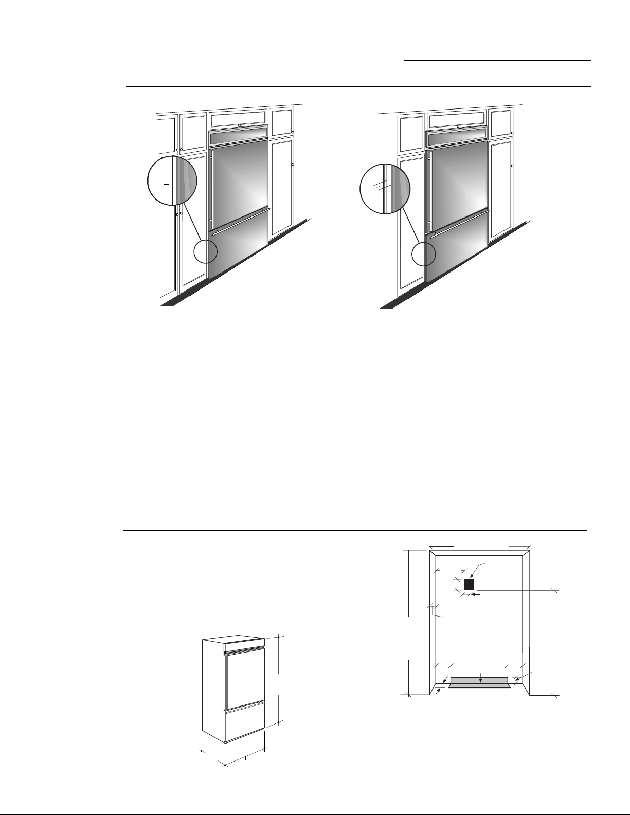
Flush or
Semi-Flush
Enclosure
Installations
Advance Planning
0"
True Flush Installation
In a flush installation,
the refrigerator doors
will align evenly with the
front face of adjacent cabinet
doors. The refrigerator blends
into the surrounding cabinetry.
Monogram built-in refrigerators can be
installed flush with typical 24-3/4" deep
cabinetr y.
When installed semi-flush, the case trim will
conceal slight gaps around the enclosure. The
refrigerator will project forward approximately 3/4" beyond the front face of surrounding cabinetry.
36" Stainless Bottom Mount Refrigerators
3/4"
Semi-Flush Installation
These refrigerators
can also be installed
semi-flush into an enclosure
using the minimum cutout
width. The case trim creates a
frame around the opening.
Side Panels Requirements:
• Side panels are not required whenever the
refrigerator is installed into an enclosure or
between pantry and oven cabinets.
• Side panels are required whenever the sides
of the refrigerator are exposed.
• Side panel sizes vary depending on the type
of installation being made.
To accomplish an attractive installation,
you must:
1. Determine the need for side panels.
2. Determine side panel thickness.
3. Order matching side panels from the
cabinet manufacturer. Be sure to provide
the exact dimensions.
Enclosure
•To achieve a flush fit the finished cutout
width must be at least 36" wide.
Cutout and
Product
•In a semi-flush installation, the finished
cutout must be 35-1/2".
•The electrical and water locations must be
Dimensions
located as shown for either type of
installation.
24-3/4"
36"
83-1/2" Min
84-1/2" Max
*36" for for a flush installation.
35-1/2" Min. for a semi-flush installation.
Note: Additional cutout width may be required when side panels
are used. Add side panel thickness to the finished cutout to
calculate rough-in width. See installation examples on
the following page.
3
Design Information
36" Stainless Bottom Mount Refrigerators
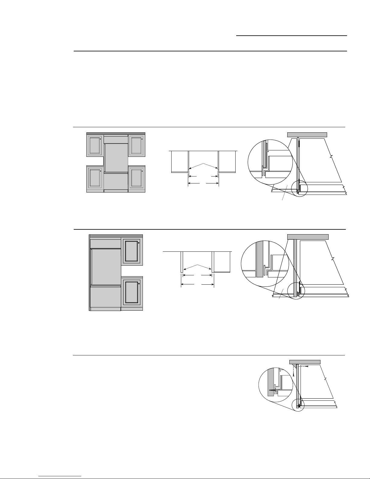
Installation
Between
Base &
Wall Cabinets
Installation
Side panels are required whenever the sides
of the refrigerator will be exposed.
1/2" to 3/4" side panels are normally set into
place and fastened to adjacent cabinetry or to
the back wall before rolling the refrigerator
into the opening.
Flush and Semi-Flush
Installations
1/4" Thick
Side Panels
Finished Dim.
Roughed-In Dim.
NOTE: 1/4" thick side panels can be inserted
into the case trim, making the rough-in the same
as the outside trim width, 36".
Flush and Semi-Flush
Installations
Therefore, the rough-in dimensions must
allow for side panel thickness. In both a flush
and semi-flush installation, the finished
dimension, (the width of the opening after
side panels are installed), must accommodate
the full width of the refrigerator.
See page 9 for side panel sizes.
Refrigerator
Cabinet
35-1/2"
36"
Refrigerator door
Cabinet
1/4" Side Panels. Insert end of
side panel into trim
At End-of-Run
Frameless
Cabinets
Finished Dim.
Roughed-In Dim.
NOTE: 1/2" thick side panels shown. Side panels
can be any thickness. Add side panel thickness to
outside trim width (36") to calculate the rough-in
dimension. The leading (front) edge must be
finished to match surrounding cabinetr y.
Side panels, 1/2" minimum
thickness are required when
using frameless cabinets. The
side panel acts as a spacer
between the cabinet and the case
trim and prevents interference
with cabinet door swing. The
leading (front) edge must be
finished to match surrounding
cabinetr y.
1/2" Thick
Side Panels
36"
37"
1/2" To 3/4" Side Panels. Leading
Edge Flush With Cabinet
Refrigerator
Cabinet
Refrigerator door
Cabinet
1/2" To 3/4" Side Panels. Leading
Edge Flush With Cabinet
Refrigerator
Cabinet
Refrigerator door
4
Installation Preparation
36" Stainless Bottom Mount Refrigerators
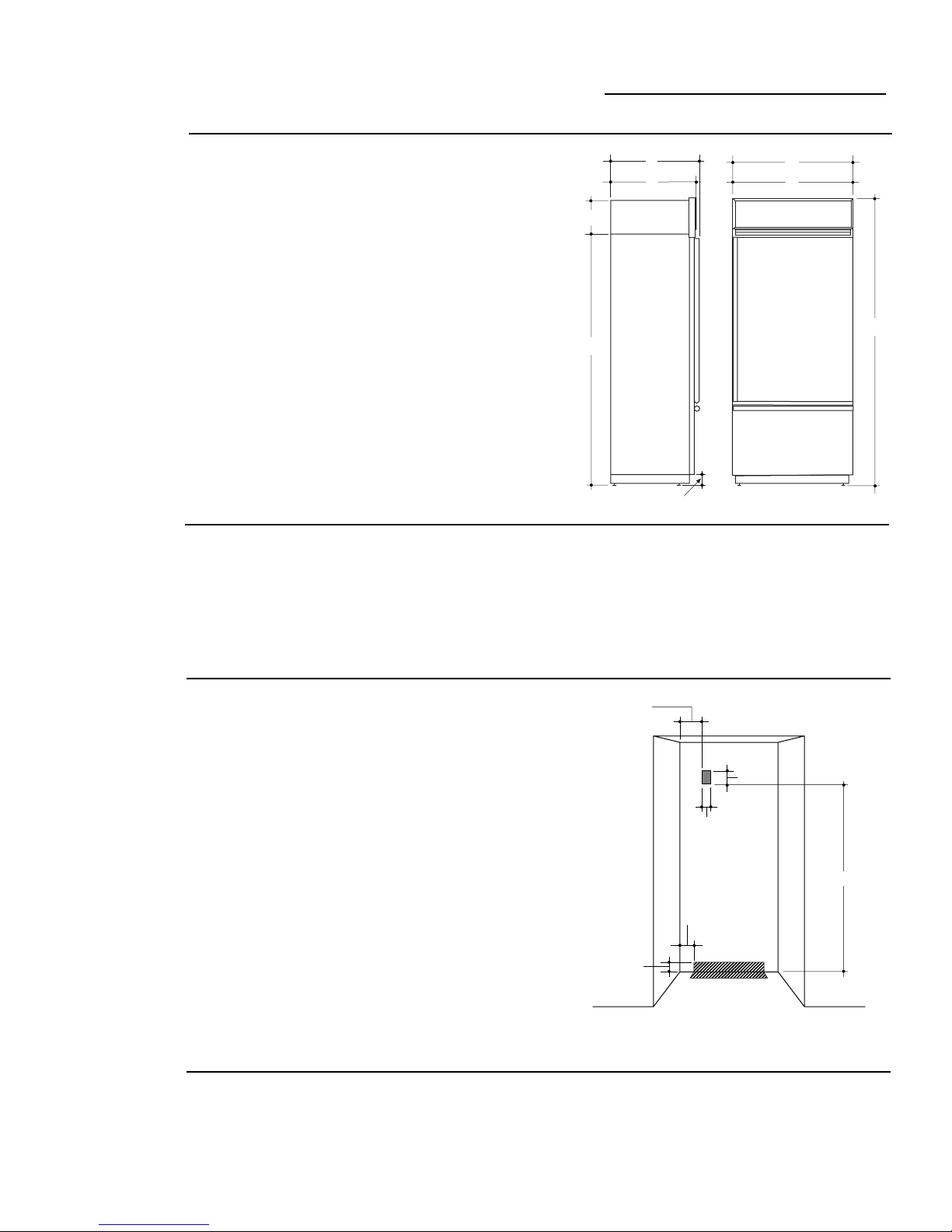
Product
Dimensions
Clearances
ZICS36N RH
Handle on the left side, the door swings left to
right.
ZICS36N LH
Handle on the right side, the door swings right
to left.
A – 36" outside trim width
B – 35" case width
C – 10-3/4"
D – 72-1/4"
E – 84" Shipping height
Adjustable from 83-1/2" to 84-1/2"
F – 24-3/4" (excluding handles)
G – 26-3/4" (including handles)
H – 4"
Caution:
bottom – be extra careful when moving.
These refrigerators are equipped with special
hinges that allows the door to swing out and
away from the cabinet. No clearances are
required on the sides.
Refrigerators are much heavier at the top than at the
G
F
C
D
H
When the refrigerator is installed in a corner:
•A 4" min. clearance on the hinge side will
assure a 90° door opening and access to all
drawers.
•A 10" clearance on the hinge side is required
for removal of pans.
A
B
E
Electrical and
Water
Connection
Locations
Accessory
Grille Panel
Kits
The water line can be routed through
the floor or back wall.
•Water line should be:
–Approximately 3-1/2" from the floor on the
back wall, or 3-1/2" from the back wall on the
floor.
–At least 5" from either side of the opening.
A 115 volt, 60 Hz. 15 or 20 amp power supply
is required. An individual properly grounded
branch circuit or circuit breaker is recommended, as noted on the rating plate. The
rating plate is located on the top on the
evaporator box and is visible when grille
panel is removed.
•Locate the electrical outlet within 5" x 7"
shaded area shown.
–7-1/2" from the left side.
•Between 74" and 81" from the floor.
These models are factory set for 84" installation
height. Adjustments to 83-1/2" or 84-1/2"
heights can be made by changing the grille
panel.
Electrical Outlet
Location 7-1/2"
7"
5"
74"
5"
3-1/2"
Water Location
Important:
cord, locate the electrical outlet as shown.
Order ZGCSS36RH (right hand) or
ZGCSS36LH (left hand) Grille Panel Kit.
These kits include 2 grille panels, for 83-1/2"
and 84-1/2" installation heights.
To insure a flush fit and access to the power
5
 Loading...