

Page 1

MONOGRAM 30" INDUCTION COOKTOP
ADA
ZHU30RDPBB
COMPLIANT
GOURMET GUIDED COOKING
Elevate your culina ry skills. Use the Hestan Cue™ pan included with
your new cooktop and this sma rt cooking system to create a n array
of chef-inspired recipes—perfectly
GLIDE TOUCH CONTROLS
Easy to use electronic controls allow you to precisely raise or lower
heat in a n instant with one easy swipe
FOUR INDUCTION COOKING ELEMENTS
Enjoy a new level of rapid, precise hea ting with a cool-to-the-touch
surface that’s easy to clea n
11" 3700W INDUCTION ELEMENT
Rapidly boil water with our most powerful induction element
SYNCBURNERS
Control two 7" elements simultaneously to evenly heat large
cookware or the included griddle
MELT SETTING
Gently melt delicate foods without burning or scorching
CONTROL LOCK CAPABILITY
Protects against unintended activa tion
CUSTOM SETTINGS
Personalize your cooktop settings to fit your cooking style
PAN PRESENCE & SIZE SENSORS
Cook efficiently with elements that hea t to the size of your pan a nd
shut off when no pan is present
FLUSH-MOUNT CAPABLE
Optional accessory kit enables the cooktop to be flush inset into the
countertop for a sleek, modern look
PRECISION COOKING
Achieve restaura nt quality results with an optional probe tha t
wirelessly controls the temperature of your food. Ideal for Sous
Vide, Slow Cooking, making candy, etc., or for a ny other cooking
that requires precise control of tempera ture over time
For questions about your
appliance, please call 1-800-626-2000.
PAGE 1 OF 5
Product Specication Created 12/20
Page 2
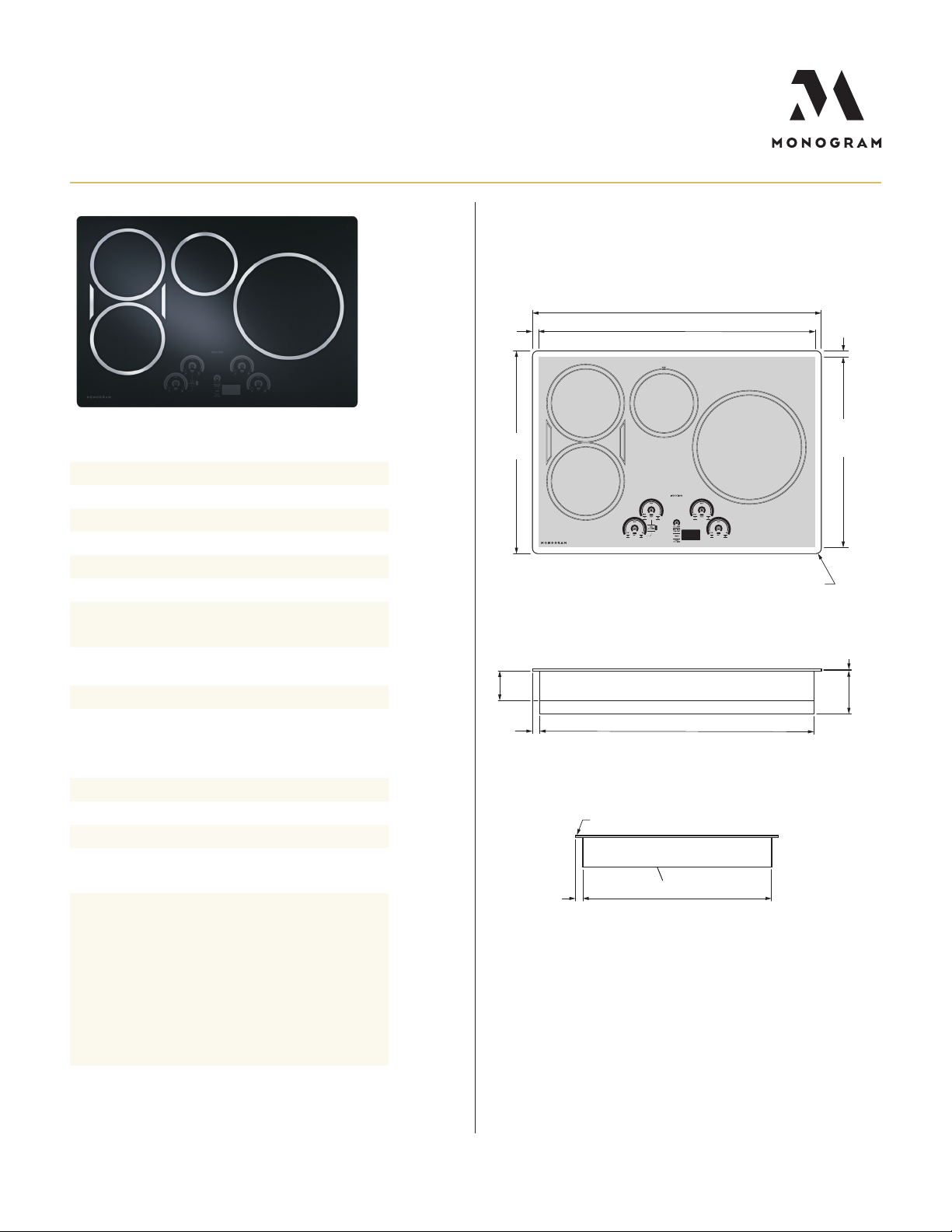
OVERALL DIMENSIONS
SPECIFICATIONS
Overall Width 29 3/4" (75.6 cm)
Overall Depth 20 7/8" (53.0 cm)
Overall Height 4 5/8" (11.8 cm)
Cut-out Width 28 1/2" (72.4 cm)
Cut-out Depth 19 5/8" (49.9 cm)
Conduit Length 48" (122 cm)
Electrical Rating
Recommended Circuit
Breaker Size
7400W at 240V/60Hz
6400W at 208V/60Hz
40 Amps
Net Weight 45 lbs. (20.4 kg)
Approx. Shipping Weight 51 lbs. (23.1 kg)
OPTIONAL ACCESSORIES
Precision Cooking Kit JXPROBE1
Flush-Mount Kit JXFLUSH1
Griddle JXGRIDL1
5/8"
(1.6)
Cutout
overlap
20 7/8"
(53.0)
3 1/16"
(7.8)
3/4"
(1.9)
29 3/4" (75.6)
28 1/2" (72.4)
Cutout width
TOP VIEW (SHOWING CUTOUT OVERLAP)
R 1/2" (1.3)
All Four Corners
Baffle
28 1/4" (71.8)
FRONT VIEW
Front of Cooktop
5/8"
Cutout
overlap
19 5/8"
(49.9)
Cutout
depth
3/16"
(0.5)
4 7/16"
(11.3)
(1.6)
ATTENTION ELECTRICIAN:
This cooktop is provided with a 48" exible conduit and
must be hard wired (direct wired) into an approved
junction box and be properly grounded. It is not permitted to use a “plug and receptacle” type installation
on this cooktop.
Use a two-wire, three conductor 208/240 VAC, 60
Hertz electrical system. A white (neutral) wire is not
needed for this cooktop
For more details refer to the installation instructions
for this product.
For questions about your
appliance, please call 1-800-626-2000.
3/4"
(1.9)
19 7/16" (49.4)
SIDE VIEW
Dimensions in parentheses a re in centimeters unless otherwise noted.
Actual product dimensions may vary due to ma nufacturing tolerances.
PAGE 2 OF 5 Product Specication Created 12/20
Page 3

INSTALLATION
3"
(7.6) min
16" (40.6) min
To electrical junction box
Locate electrical junction box
at least
16" below the countertop
15"
(38.1)
min
30 " (76.2)
Cabinet base
SIDE VIEWFRONT VIEW
DRAWER
13"
(33.0) max
B
E
A
16" (40.6) min
To electrical junction box
Locate electrical junction box
at least
16" below the countertop
C
15"
(38.1)
min
D
3"
(7.6) min
DRAWER
F
30 " (76.2)
Cabinet base
SIDE VIEWFRONT VIEW
COUNTERTOP CUT-OUT DIMENSIONS ADA INSTALLATION
H
28 1/2" (72.4) min
28 5/8" (72.7) max
Cutout width
1 3/4" (4.5) min
Clearance between the
rear edge of the cutout
and the nearest wall
behind the cooktop
I
5"
(12.7) min
19 5/8" (49.9) min
19 3/4" (50.2) max
Cutout depth
13"
(33.0) max
G
HELPFUL TIPS
A
Wall coverings, countertop and ca binets
surrounding cooktop must be able to
withstand tempera tures of
up to 200ºF.
B
Minimum 30" cleara nce from countertop
to unprotected overhead surfaces, when
no ventilation hood or microwave oven is
installed.
C
When using a ventila tion hood or microwave
oven above the cooktop, see hood or
microwave installation instructions for
minimum overhead cleara nce dimensions.
D
Minimum 15" of cleara nce from countertop
to nearest overhead surface on both sides of
cooktop. Make sure to include any lighting
rail covers in calcula tion.
E
Minimum 2" distance from edge of cutout to
nearest adjacent side wall below
upper cabinets.
F
Install an approved junction box where it
can be easily reached through the front of
the cabinet where the cooktop is loca ted.
IMPORTANT: For serviceability, the junction
box must be located where it will allow
considerable slack in the 48" long conduit.
G
Maximum 13" depth of unprotected overhead
surfaces, when no ventilation hood or
microwave oven is installed.
H
For Americans with Disa bilities Act (ADA)
forward approach installa tion: Minimum 5"
cleara nce between the top of the countertop
and the enclosure. e enclosure must be
made of at least 1/4" thick wood ma terial, and
must have an access pa nel installed in order
to provide access to the junction box and
hold-down brackets, and to allow for service
of the cooktop.
For more details refer to the installa tion
instructions for this product.
FRONT
2 1/2" (6.4) min
TOP VIEW OF CUTOUT SIDE VIEW
Clearance between the
front edge of the cutout
and the front edge of the
countertop
Dimensions in parentheses a re in centimeters unless otherwise noted.
For questions about your
appliance, please call 1-800-626-2000.
PAGE 3 OF 5 Product Specication Created 12/20
Page 4

ELECTRIC
Wall oven
ELECTRIC
Wall oven
ELEC.
cooktop
4 3/4"
(12.1) max
SIDE VIEW FRONT VIEW
ELECTRIC
Wall oven
ELECTRIC
Wall oven
ELEC.
cooktop
4 3/4"
(12.1) max
31 1/4"
(79.4) min
From top
surface of
countertop
to top
surface of
wall oven
platform
SIDE VIEW FRONT VIEW
5"
(12.7) min
ELECTRIC
Wall oven
ELECTRIC
Wall oven
ELEC.
cooktop
ELEC.
cooktop
4 3/4"
(12.1) max
SIDE VIEW FRONT VIEW
5"
(12.7) min
ELECTRIC
Wall oven
ELECTRIC
Wall oven
ELEC.
cooktop
ELEC.
cooktop
4 3/4"
(12.1) max
31 1/4"
(79.4) min
From top
surface of
countertop
to top
surface of
wall oven
platform
SIDE VIEW FRONT VIEW
INSTALLATION ABOVE WALL OVEN
C
D
31 1/4"
(79.4) min
From top
surface of
countertop
to top
surface of
wall oven
platform
D
E
4 3/4"
4 3/4"
(12.1) max
(12.1) max
SIDE VIEW FRONT VIEW
SIDE VIEW FRONT VIEW
INSTALLATION ABOVE WARMING DRAWER
H
5"
5"
(12.7) min
(12.7) min
A
ELECTRIC
ELECTRIC
Wall oven
Wall oven
B
F
ELECTRIC
ELECTRIC
Wall oven
Wall oven
ELEC.
ELEC.
cooktop
cooktop
G
ELEC.
ELEC.
cooktop
cooktop
G
HELPFUL TIPS
A
Note this cooktop is only
approved for installation a bove
specific wall ovens as labeled on
this unit.
B
Warming drawers a re approved
for installation below only certa in
specified cooktop models. See the
label a ttached to the top of the
warming drawer or underside
of the cooktop for approved
combinations.
C
When installing this cooktop
above a single wall oven, do not
install the baffle.
D
Mainta in a minimum distance
of 31-1/4" from the top surface
of the countertop to the wall
oven platform to ensure tha t the
cooktop and wall oven do not
interfere with each other (see
picture).
E
e cooktop platform must be a
minimum height of 4-3/4" from
the floor to ensure that the ha ndle
does not hit the floor when the
door is opened.
F
Junction box location for wall
oven (may also be located in
adjacent cabinet).
G
Electrical connection for cooktop
must be located in a n accessible
adjacent location to the right
(may also be located in adjacent
cabinet).
H
When installing the cooktop
above a warming drawer, a solid
barrier must be installed a t least
5" from the top of the countertop.
Use any solid ma terial such as
1/4" thick plywood. Allow at least
a 2" a ir gap between the front of
the barrier a nd the inside of the
cabinet a nd at least 1/4" air gap
between the barrier a nd the top of
the warming drawer.
SIDE VIEW FRONT VIEW
SIDE VIEW FRONT VIEW
For more details, refer to the installa tion instructions for this product on Monogram.com.
Dimensions in parentheses a re in centimeters unless otherwise noted.
For questions about your
appliance, please call 1-800-626-2000.
PAGE 4 OF 5 Product Specication Created 12/20
For more details refer to the
installation instructions for this
product
Page 5

FLUSH MOUNT INSTALLATION
Countertop
R 5/8" (1.6)
3/4" (1.9)
Width of rabbet
in countertop
1/4" (0.6) max
Depth of rabbet
in countertop
21 1/8"
(53.7)
30" (76.2)
FRONT VIEW
X X
Countertop
ELEC.
Wall Oven
4 3/4"
(12.1) max
R 5/8" (1.6)
All Four Corners
3/4" (1.9)
Width of rabbet
in countertop
1/4" (0.6) max
Depth of rabbet
in countertop
21 1/8"
(53.7)
30" (76.2)
5 1/2"
(14.0) min
FRONT VIEW
X X
SIDE VIEW SIDE VIEW
31 1/4"
(79.4) min
From top
surface of
countertop
to top
surface of
wall oven
platform
Countertop
R 5/8" (1.6)
All Four Corners
3/4" (1.9)
Width of rabbet
in countertop
1/4" (0.6) max
Depth of rabbet
in countertop
21 1/8"
(53.7)
5 1/2"
(14.0) min
HELPFUL TIPS
A
TOP VIEW OF CUTOUT SECTION X–X
FLUSH-MOUNT INSTALLATION
ABOVE WALL OVEN
D
FLUSH-MOUNT INSTALLATION
ABOVE WARMING DRAWER
F
E
G
For more details, refer to the installa tion instructions for this product on Monogram.com.
Dimensions in parentheses a re in centimeters unless otherwise noted.
PAGE 5 OF 5 Product Specication Created 12/20
For questions about your
appliance, please call 1-800-626-2000.
B
C
Through countertop showing
depth of rabbet for flush-mount
H
I
A
Use optional JXFLUSH1 kit to
flush-mount the cooktop into the
countertop. Read all installation
instructions supplied with cooktop
and kit before beginning installa tion.
B
To avoid hot cookware from
contacting the countertop surface,
the cooktop should be installed
at least 1/32" higher tha n the
countertop.
C
Use strips of wood or solid-surface
countertop material to reinforce the
countertop below the flush-mount
rabbet. For a n island or peninsular
installation secure strips to all four
sides, otherwise just secure strips to
the front and back under the cutout.
D
Note this cooktop is only approved
for installation a bove specific wall
ovens as labeled on this unit.
E
When installing this cooktop above
a single wall oven, do not install the
baffle.
F
When this cooktop is installed above
a flush-mounted wall oven, the
cleara nce from the front edge of the
countertop to the front edge of the
cooktop cutout is minimum 2-1/2"
plus the wall oven cleat setback.
G
e cooktop platform must be a
minimum height of 4-3/4" from the
floor to ensure that the ha ndle does
not hit the floor when the door is
opened.
H
Warming drawers a re approved
for installation below only certa in
specified cooktop models. See the
label a ttached to the top of the
warming drawer or underside of the
cooktop for approved combinations.
I
When installing the cooktop above
a wa rming drawer, a solid barrier
must be installed at least 5-1/2" from
the top of the countertop. Use any
solid material such as 1/4" thick
plywood. Allow at least 1/4" a ir gap
between the barrier a nd the top of
the warming drawer.
For more details refer to the installa tion
instructions for this product
 Loading...