

Monogram 36, 48"", ZGU484NG, ZGU486NR, ZGU486ND Installation Instructions Manual
...
31-10691
04-08 JR
Installation
Instructions
36" and 48"
Professional Rangetops
Tables de cuisson
professionnelles de 36" (91 cm)
et de 48" (122 cm)
Instructions d’installation
La section française commence à la page 18
Estufas profesionales
de 36" (91 cm) y 48" (122 cm)
Instrucciones de instalación
La sección en español empieza en la página 34
Safety Information
BEFORE YOU BEGIN
Read these instructions completely and carefully.
•
IMPORTANT — Save these instructions for
local inspector’s use.
•
IMPORTANT — Observe all governing
codes and ordinances.
• Note to Installer — Be sure to leave these
instructions with the Consumer.
• Note to Consumer — Keep these instructions
with your Owner’s Manual for future reference.
• Completion Time — 1 to 3 hours.
•
Proper installation is the responsibility of the
installer. Product failure due to improper
installation is not covered under the warranty.
See Owner’s Manual for warranty information.
WARNING
This appliance must be properly grounded.
See “Electric S
For Monogram local ser
1.800.444.1845.
For Monogram Ser
1.800.561.3344.
For Monogram Parts and Accessories, call
1.800.626.2002.
If you received a damaged rangetop, you should
contact your dealer
upply.”
vice in your area,
vice in Canada, call
.
Vent hood Combinations:
It is recommended that these rangetops be installed
in conjunction with a suitable overhead vent hood.
• Install a hood with at least 1200 CFM above a 48"
wide rangetop
• Install a hood with at least 600 CFM above a 36”
rangetop.
Due to the high heat capacity of this unit, particular
attention should be paid to the hood and ductwork
installation to assure it meets local building codes.
.
WARNING:
Clearances to horizontal surfaces above the
rangetop, measured to the cooking surface:
• Installations without a hood require 48” minimum
to combustibles.
• A custom hood installation with exposed
horizontal combustibles surfaces must have
an Auto-On featur
• For other installations with a hood, refer to hood
installation instructions for specific hood
clearances.
e.
CAUTION:
These rangetops are extremely heavy. Due to the
weight and size of the rangetop and to reduce the
risk of personal injury or damage to the product:
TWO PEOPLE ARE REQUIRED FOR PROPER
INST
ALLATION
.
In the Commonw
• This product must be installed by a licensed
plumber or gas fitter.
When using ball type gas shut off v
•
shall be T-handle type.
• A flexible gas connector, when used, must not
exceed 3 feet
ealth of Massachusetts:
.
es, they
alv
Installation must conform with local codes. In the
absence of local codes, the rangetop must comply
with the National Fuel Gas Code, ANSIZ223.1/
NFPA 54, latest edition and National Electrical Code
ANSI/NFP
must conform with the current Natural Gas
Installation Code, CAN/CGA-B149.1 or the current
opane Installation Code, CAN/C
Pr
with local codes where applicable. This rangetop has
been design-certified by CSA International according
to ANSI Z21.1, latest edition and Canadian Gas
Association according to CAN/CGA-1.1 latest edition.
Leak testing of the appliance shall be conducted
according to the manufacturer’s instructions.
A 70 latest addition. In Canada, installation
GA-B149.2, and
2
Design Information
CONTENTS
Design Information
Models Available......................................................................3
Backsplash Accessories ......................................................3
Product Dimensions and Clearances
for 48” Wide Models ..............................................................4
Product Dimensions and Clearances
for 36” Wide Models ..............................................................5
Installation Options ..............................................................6
Installation Preparation
Tools and Materials Required ..........................................7
Power Supply Locations ....................................................7
Remove Packaging ................................................................8
MODELS AVAILABLE
Monogram rangetops are factory set for natural
gas or LP gas. Order the model for your installation
situation.
48” Natural Gas Models:
ZGU484NG – 4 gas burners, grill and griddle
ZGU486NR – 6 gas burners and grill
ZGU486ND – 6 gas burners and griddle
48” LP Gas Models:
ZGU484L
ZGU486LR – 6 gas burners and grill
ZGU486LD – 6 gas burners and griddle
G – 4 gas burner
s, grill and griddle
Installation Instructions
Step 1, Cut the Countertop Opening..............................9
Step 2, Install the Rangetop ............................................10
Step 3, Connect Rangetop to Gas ................................10
Step 4, Connect Electrical ................................................11
Step 5, Check Burners ......................................................11
Finalize Installation ..............................................................11
Installation Checklist ..........................................................11
Install the Rangetop Backsplash Accessory ..........12
Install the Adjustable
Backsplash Accessory................................................13, 14
Gas Conversion..............................................................15, 18
36” Natural Gas Models:
ZGU364ND – 4 gas burners and griddle
ZGU364NR – 4 gas burners and grill
ZGU366N – 6 gas burners
36” LP Gas Models:
ZGU364LG – 4 gas burner
ZGU364LR – 4 gas burners and grill
ZGU366L – 6 gas burner
s and griddle
s
BACKSPLASH ACCESSORIES
All models require 12" minimum clearance
to a vertical combustible surface at the rear.
If clearance is less than 12", the entire surface
of the back wall above the countertop and the full
width of the rangetop must be protected by a
backsplash. The backsplash must be constructed
of non-combustible material, such as metal,
ceramic tile, brick, marble or other stone.
Two Backsplash Accessories Available:
• The 12" high stainless steel backsplash accessory
is available. Use this backsplash in combination
with a custom, non-combustible backsplash built
beyond the 12” height. The combined height
of the backsplash accessory and the custom
backsplash must r
or when there is no hood, to 48” above
the cooking surface.
each the bottom of a hood,
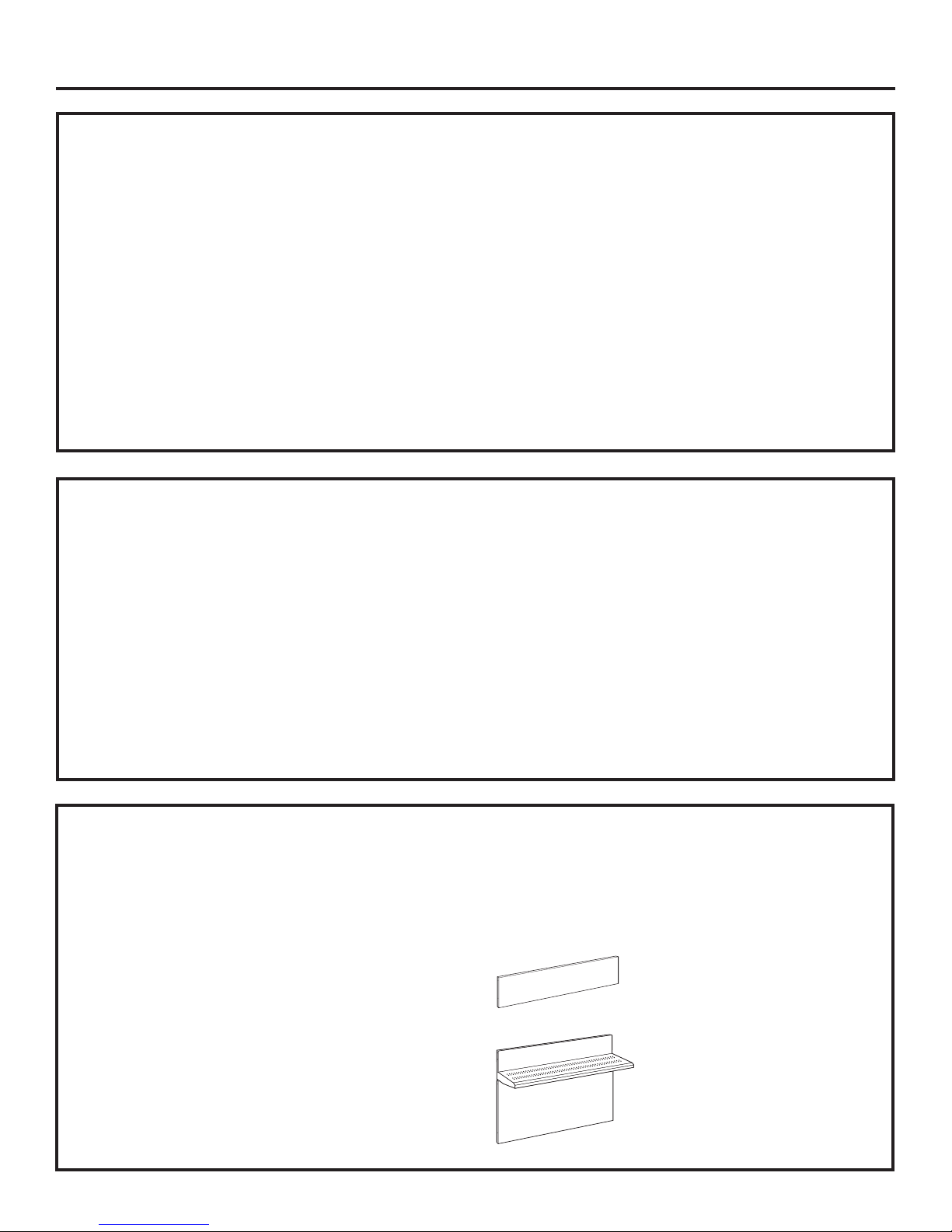
• An adjustable 30" to 36" high backsplash with shelf
is also av
betw
of the hood. The shelf is positioned so that
heat lamps fr
ofessional hood ar
pr
ailable. This backsplash fills in the space
een the top of the rangetop and the bottom
om the bottom of a Monogram
ds the shelf
ected tow
e dir
12" High Backsplash
ZX12B48PSS, for 48" wide rangetops
ZX12B36PSS, for 36" wide rangetops
30" to 36" Adjustable Height Backsplash
With Shelf
ZXADJB48PSS, for 48" wide rangetops
ZXADJB36PSS, for 36" wide rangetops
ar
3
.

Design Information
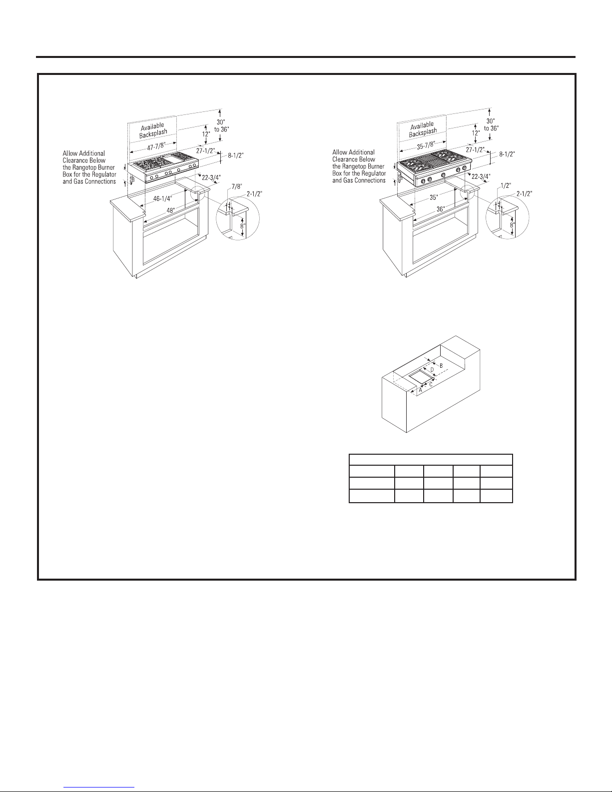
PRODUCT DIMENSIONS AND CLEARANCES FOR 48” MODELS
27-1/2” to
7-7/8
4
” W
idth
Front of
Bullnose
Universal Utility Locations
WARNING:
Installations without a hood
require 48
above the rangetop. A custom hood
installation with exposed horizontal
combustible surfaces must have
an Auto-On feature. Refer to hood
installation instructions for specific
hood clearances.
The surface of the entire back wall
above the countertop and below
the hood must be covered with
a non-combustible material such
as metal, ceramic tile, brick, marble
or other stone.
"
minimum to combustibles
13” Max.
18” Min.
8-1/2”
Height
48” Minimum
to Combustibles
*48”
46-1/4”
ocate gas
L
inlet on back
wall or on
floor 2” from
back wall.
Non-combustible
material
22-3/4” Min.
48”
12” Minimum to
12” Minimum
Each Side
2”
7”
1
Adjacent Wall
1
6”
7/8”
2-1/2”
8”
ADDITIONAL CLEARANCES:
Allow 12" minimum clearance to an adjacent wall on
each side.
Working areas adjacent to the rangetop should have
18" minimum clearance between countertop and the
bottom of the w
* The opening betw
to allow the rangetop to slide back against the wall.
all cabinet
een a 4” high backsplash must be 48”
.
4
12” Minimum to
Combustibles or 0” to
non-combustible material
above the cooking sur
0”
Clearance
face
Combustibles
48” Min. to

Design Information
PRODUCT DIMENSIONS AND CLEARANCES FOR 36” MODELS
35-7/8” Width
27-1/2” to
Front of
Bullnose
8-1/2”
Height
Locate gas
inlet on back
wall or on
floor 2” from
back wall.
Universal Utility Locations
2”
17”
16”
WARNING:
Installations without a hood
require 48"minimum to combustibles
above the rangetop. A custom hood
installation with exposed horizontal
combustible surfaces must have
an Auto-On feature. Refer to hood
installation instructions for specific
hood clearances.
The surface of the entire back wall
above the countertop and below
the hood must be covered with
a non-combustible material such
as metal, ceramic tile, brick, marble
or other stone.
13” Max.
18” Min.
48” Minimum
to Combustibles
*36”
35”
Non-combustible
material
22-3/4” Min.
36”
12” Minimum to
12” Minimum
Each Side
Adjacent Wall
1/2”
2-1/2”
8”
ADDITIONAL CLEARANCES:
Allow 12" minimum clearance to an adjacent wall on
each side.
Working areas adjacent to the rangetop should have
18" minimum clearance betw
bottom of the wall cabinet.
* The opening between a 4” high backsplash must be 36”
to allow the rangetop to slide back against the wall.
een counter
top and the
5
12” Minimum to
Combustibles or 0” to
non-combustible material
above the cooking sur
0”
Clearance
face
48” Min. to
Combustibles

*
**
8”
Countertop
Level
Cooktop
1/2” Above Adjacent
Countertops.
Cooktop
1/2” Above Adjacent
Countertops.
INSTALLATION OPTIONS
Design Information
Back edge
of chamfer
* Minimum cabinet cutout depth from
the back of the rear trim to the back
finished edge of the control panel typically, the minimum cabinet depth
(front to back). Maximum cabinet cutout
depth is 26” minus the countertop
overhang.
Rangetop
Finished back edge
of control panel
†
Include the overhang of the rear trim when countertop continues behind the product.
The overhang is decorative only. The weight of the rangetop is fully supported by the side trims.
** Maximum countertop cutout depth
from the back of the rear trim
to the back edge of chamfer at the
sides of the control panel - typically,
the maximum countertop cutout depth
(front to back). Minimum countertop
cutout depth is 25-1/4”.
Rangetop
1/2” Above Adjacent
Countertops
†
1/2” Above Adjacent
Countertops
ds from
ar
Contr
ol panel pr
ojects for
w
standard depth cabinets.
Front of deep cabinets can align with control
panel bev
eled edge.
6
Installation Preparation
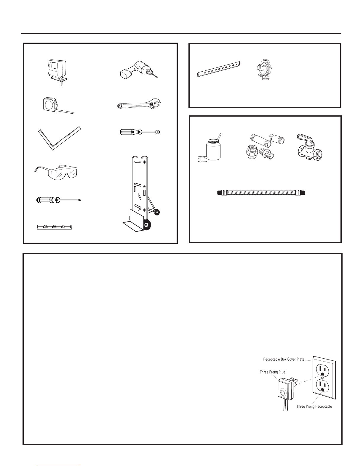
TOOLS REQUIRED
Saber Saw
Measuring Tape
Carpenter’s Square
Safety Glasses
Phillips #2 Screwdriver
Level
Drill and
Appropriate Bits
Adjustable Wrench
1/4" Driver or Wrench
Hand Truck
MATERIALS PROVIDED
Hold-Down
Strap
Regulator
MATERIALS REQUIRED (not provided)
Joint
Sealant
5-foot maximum length, 5/8" O.D. CSA-appr
(3-foot maximum length in Massachusetts only)
NOTE: Purchase new flexible line; do not use
previously used flexible gas line.
Pipe Fittings
flexible metal gas supply
Shut Off Valve
oved
POWER SUPPLY LOCATIONS
Gas Supply:
• The natural gas models are designed to operate at 5"
water column pressure. For proper operation, the
pressure of the natural gas supplied to the regulator
must be between 7" and 13" water column.
• The LP models are designed to operate at 10" water
column pressure. For proper operation, the pressure
of the LP gas supplied to the regulator must be between
11" and 13" w
• Locate the pipe stub on the back wall or floor
(see “Product Dimensions and Clearances”). Use 5-foot
maximum length, 5/8" O
(3-foot in Massachusetts).
• Install a manual shut-off valve in the gas line
ovided), in an easily accessible location. Mak
(not pr
the homeowner knows where and how to shut off the gas
supply to the rangetop.
ater column.
.D
. flexible gas supply line
e sur
e
Electric Supply:
These rangetops must be supplied with 120 volt, 60 Hz.,
and connected to a dedicated, properly grounded branch
circuit protected by a 15 amp circuit breaker or time
delay fuse.
d of this appliance is equipped with a
The pow
three-prong (grounding) plug which mates with a standard
three-prong grounding wall receptacle to minimize the
possibility of shock hazard from this appliance.
If the electrical service provided does not meet the above
specifications, it is r
install an approved outlet.
DO NOT, UNDER ANY
CIR
OR REMOVE THE THIRD
(GROUND) PRONG FROM
THE POWER CORD.
DO NOT USE AN EXTENSION
CORD WITH THIS APPLIANCE.
•
•
er cor
ecommended that a licensed electrician
ANCES, CUT
CUMST
Locate the electric supply
within the area shown or within reach of the rangetop’s
four-foot power cord.
To avoid tangling cord with items stored in the cabinet,
locate the receptacle on rear wall, inside the cabinet.
7
Installation Preparation
REMOVE PACKAGING
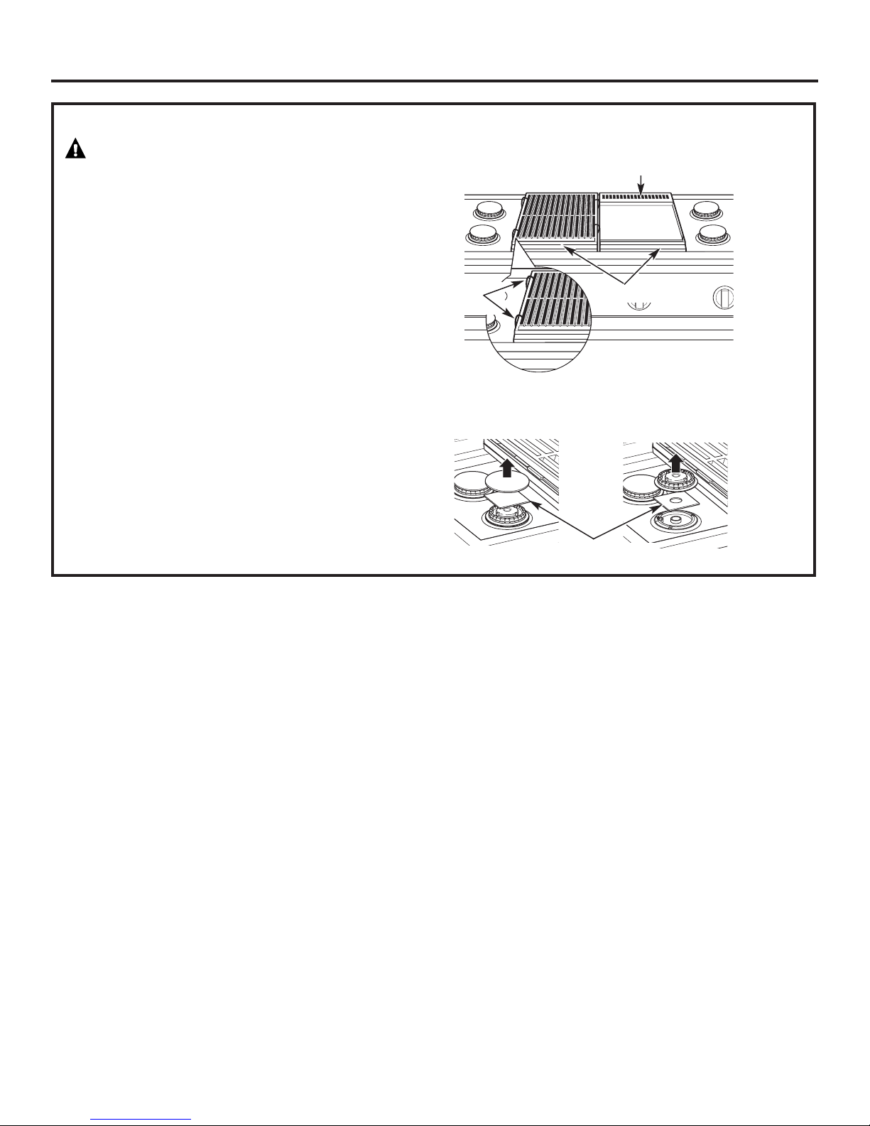
CAUTION
Stand clear. The ends of the cut metal banding may
snap toward you.
•Cut the metal banding.
•Remove packaging tape and foam.
Dispose of packaging materials properly.
•Cut the ties holding the grill grate to the grill frame.
Griddle Flue Cover
•Remove grill/griddle covers, grill grate and burner
grates.
•Lift out cast-iron griddle flue cover, grease
troughs and pads.
Ties
•Lift off burner caps and remove foam pad,
then lift off burner heads and remove foam pad.
Remove Foam Pads
Grease Troughs
8
Installation
STEP 1
Measure carefully when cutting the countertop.
Make sure sides of the opening are parallel.
• Allow 8” fr
• Allow additional clearances below the burner box
to install the regulator and make house supply
connections. Use a 90° elbow to route the gas
connections and limit interference with drawers
or other cabinetry features.
• These rangetops are designed to hang from
the countertop by their side flanges.
• Smooth any rough edges on the countertop before
installing the rangetop.
– Formica countertop edges must be finished.
The countertop must be strong enough to support
the weight of the rangetop
CUT THE COUNTERTOP OPENING
48" wide models are designed to fit in 48" or wider base cabinets 36" wide models are designed to fit in 36" or wider base cabinets
ee space below the top surface of the countertop.
.
Cutout Opening with False Bottom
Dimensions
A (Dia.) B C D
36” Rangetop 7-3/8”
48” Rangetop 8-1/4” 1-1/2” 7-1/2” 11-1/8”
1-1/2” 7-1/2” 11-1/8”
• You can construct the cutout with a false bottom to
conceal the bottom of the rangetop
– Build the false bottom using a solid material; cut a
7-1/2" x 11-1/8" hole in the left rear corner for the gas
inlet and power cord clearances.
.
9
Installation
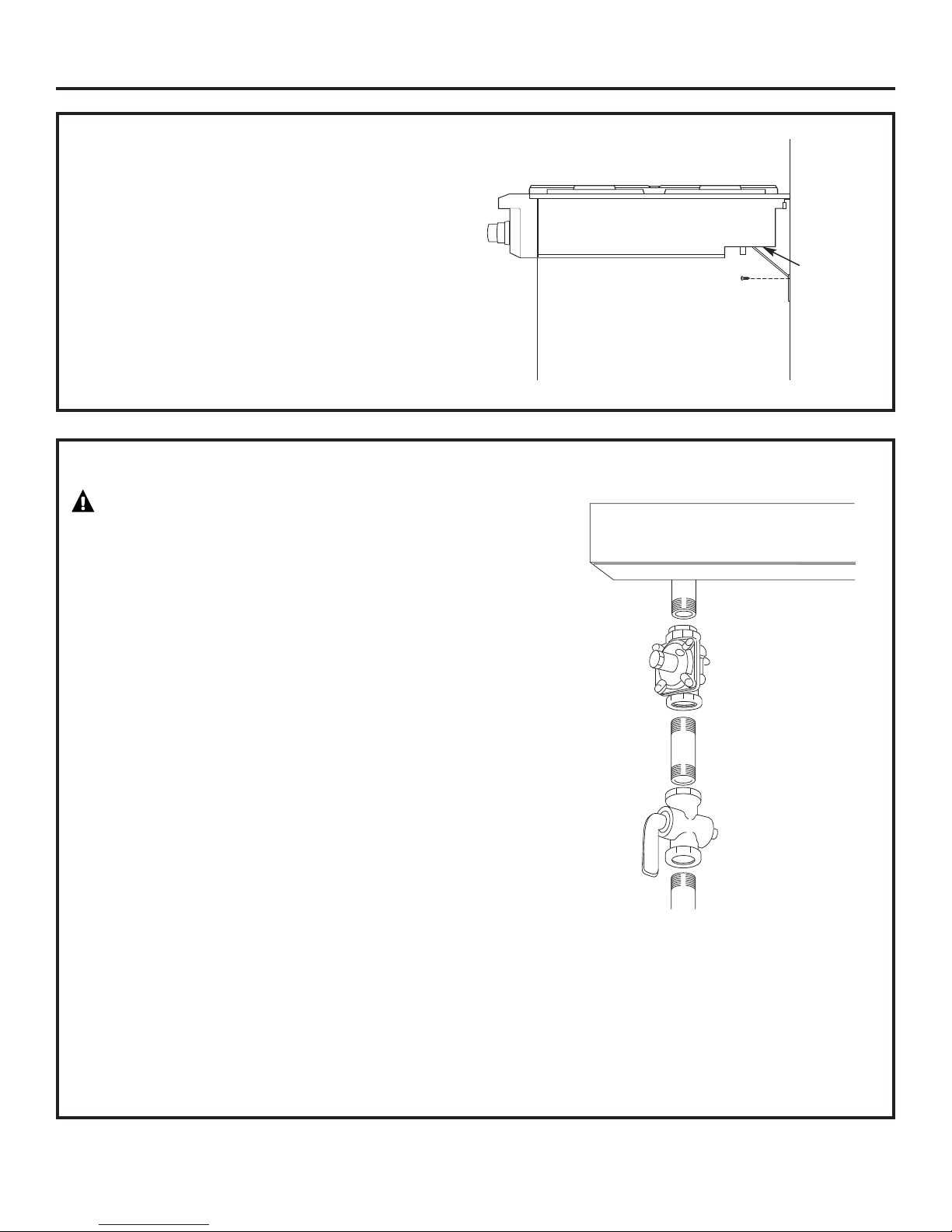
Regulator
(Supplied)
Note: Pipe stub extends
about 1” below burner
box.
Solid Piping
or Flexible
Connector
Shut-Off
Valve
Pipe Stub From
House Gas Supply
Rangetop Burner Box
1/2” N.P.T.
Gas Inlet
STEP 2
•Slide the rangetop into the opening. Make sure
the rangetop is evenly seated and supported.
•A hold-down strap with screws is provided to
secure the rangetop to the rear or side cabinet
walls.
•Remove the hold-down strap from the back
of the rangetop. Attach one end of the strap
to the back of the rangetop.
•Secure the other end of the strap as high as
possible to the cabinet back wall or adjacent
cabinet. Keep the strap as short as possible for
better security.
STEP 3
INSTALL RANGETOP
CONNECT RANGETOP TO GAS
WARNING
Do not use a flame to check for gas leaks.
A manual shut-off valve must be installed where
it will be accessible.
Hold-Down
Strap
Location and
Attachment
Back Wall
Assure that gas is turned off at the shut-off
valve.
•Install the supplied pressure regulator onto the end
of the gas inlet
•You can install a 90° elbow (not provided) onto the
gas inlet and route the gas connections to av
ference with draw
inter
features. However, it is not recommended because
it will result in a drop in gas pressure.
•Make sure the regulator is installed in the right
direction. See arrow on the underside of the
r
egulator.
TE:
NO
to pressure regulator, an approved flexible metal
appliance connector may be used between the pipe
stub and the shut
if local codes permit.
•Turn on gas and check for leaks:
Instead of using solid piping to connect
–Use a liquid leak detector at all joints and
connections in the system.
.
ers or other cabinetry
e to the pressure regulator,
alv
-off v
oid
IMPORTANT: Disconnect the rangetop and the
individual shut
system during any pr
at test pressures greater than 1/2 psig. Isolate
the rangetop fr
by closing the individual manual shut
to the rangetop during any pressure testing
of the gas supply piping system at test pressures
equal to or less than 1/2 psig.
-off valve from the gas supply piping
e testing of that system
essur
om the gas supply piping system
e
alv
-off v
10
Installation
STEP 4
• Plug power cord into properly grounded
receptacle.
• Press the button on the left side of the control
panel. The lights above the knobs should
illuminate.
STEP 5
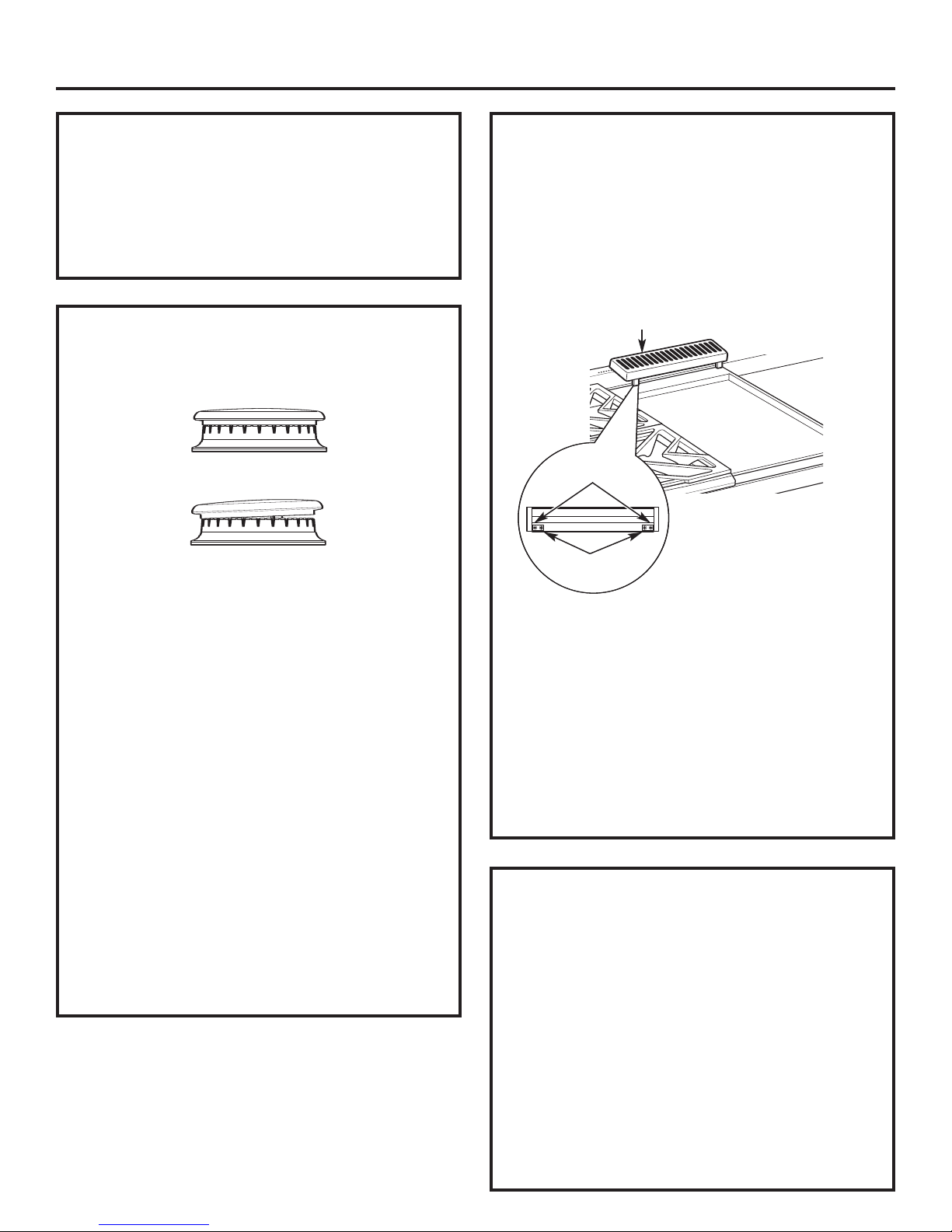
Check to be sure that burner heads and caps
are securely seated.
CONNECT ELECTRICAL
CHECK BURNERS
Burner Cap Properly Seated
Burner Cap Not Properly Seated
FINALIZE INSTALLATION
Place the burner grates over the burners.
The grates should be seated and should not rock.
The griddle is secured with screws. It is designed
to be stationary and should not be removed.
The griddle has two leveling screws beneath
the rear flue cover that can be used to adjust
to the desired slope.
Griddle Flue Cover
Leveling Screws
Clamping Screws
•Check for pr
– Push in one control knob and turn to LITE
position.
– The igniter will spark and the burner will light;
the igniter will cease spark
is lit.
– First test may require some time, while air
is flushed out of the gas line.
– Turn knob to OFF.
– Repeat the procedure for each burner.
TANT:
OR
IMP
to spark after the burners are lit, check that
each burner component is assembled pr
Refer to the Owner’s Manual.
•Burner flames should be blue and stable with no
yellow tips, excessive noise or lifting of the flame
from the burner. If any of these conditions exist,
check that the burner ports are not blocked.
If one of these conditions continues, call for
service.
oper ignition:
ing when the burner
If the igniter electr
odes continue
operly.
The two inner screws are clamping screws for
securing the griddle in place. Loosen these two
screws before leveling. Do not remove these two
screws.
The tw
remove these two screws. They can be turned to
level the griddle or to provide a forward slope to
help grease and oils to drain away from the food
being cooked.
After leveling the griddle, hand-tighten
the clamping screws; do not over-tighten.
o outer screws are leveling screws. Do not
INSTALLATION CHECKLIST
❑ Mak
❑ Mak
❑ The serial plate for your rangetop is located
❑ R
11
e sure all controls are left in the OFF
position.
e the flow of combustion and
e sur
ventilation air to the rangetop is unobstructed.
on the bottom of the rangetop. In addition
to the model and serial numbers, it tells you
the ratings of the burner
e the rangetop was adjusted
and pr
for when it left the factory.
Double check to make sure everything
in this manual has been completed. Rechecking
st
essur
eps:
echeck S
eps will ensur
t
e safe use of the ranget
s and the type of f
op
uel
.
ZX12B30PSS, ZX12B36PSS, ZX12B48PSS Accessory Installation
OPTIONAL ACCESSORIES—12" HIGH BACKSPLASH
WARNING:
To prevent ignition of combustible materials,
the entire back wall above the range must
be protected by a backsplash constructed
of non-combustible material.
This stainless steel backsplash accessory
must be installed in combination with a custom,
non-combustible backsplash built beyond
the 12" height of the backsplash.
BEFORE YOU BEGIN
Read these instructions completely
and carefully.
IMPORTANT: Save these instructions for local
inspector’s use.
IMPORTANT: OBSERVE ALL GOVERNING CODES
AND ORDINANCES.
NOTE TO INST
instructions with the Consumer
NOTE T
with your Owner
This kit pr
backsplash for 30", 36" or 48" Monogram
Professional Ranges and Ranget
O CONSUMER: Keep these instructions
ALLER: Be sur
’s Manual for future reference.
ovides for the installation of a 12" high
TOOLS AND MATERIALS REQUIRED
es to pr
Glov
•
• T-15 and #2 Phillips screwdrivers
• Drill with 3/32" and 9/64" bits
Safety glasses
•
• Level
• Pencil
otect against sharp edges
e to leave these
.
ops.
all Support
W
Panel
Cover Panel
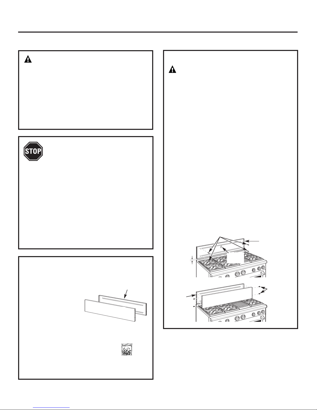
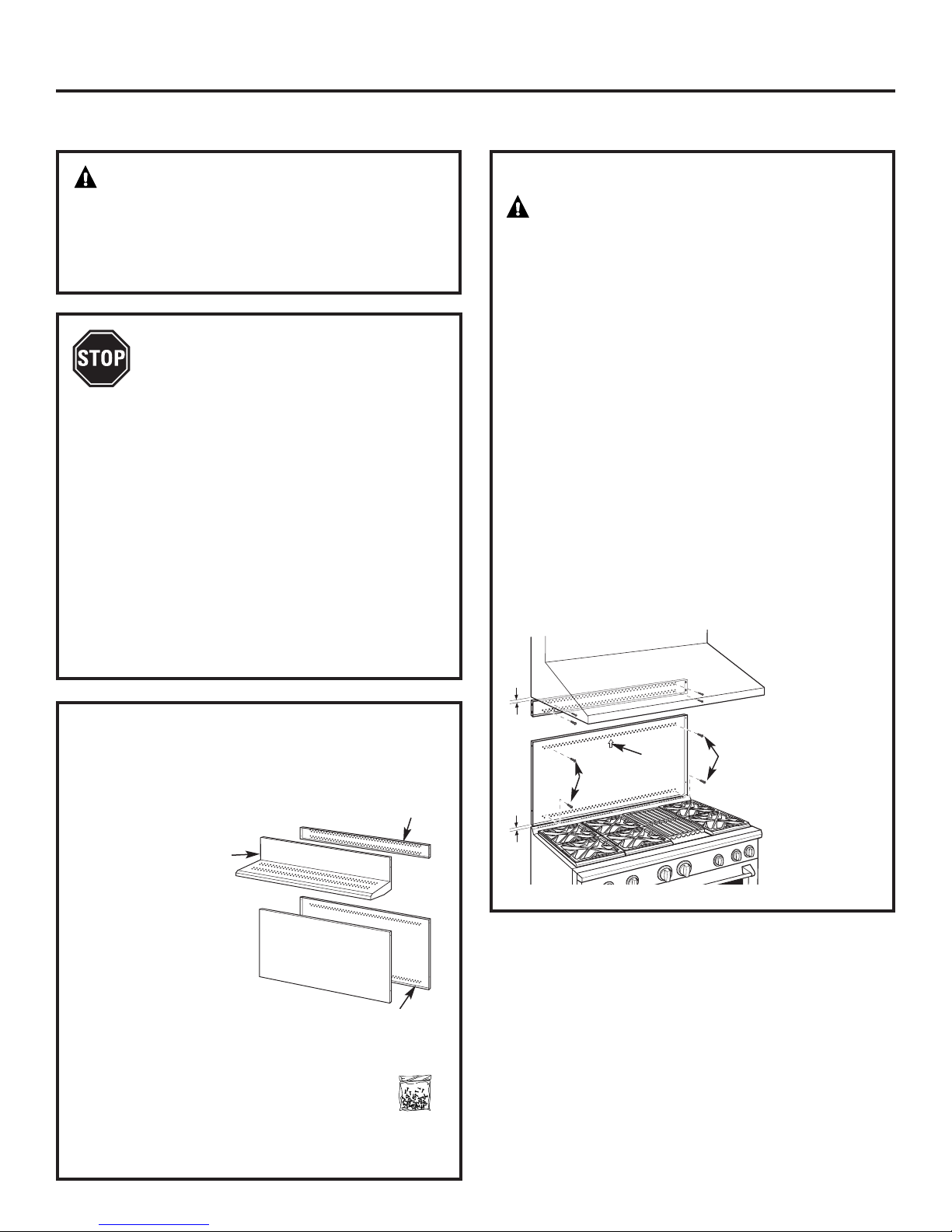
INSTALL 12" BACKSPLASH
WARNING: This backsplash must
be securely fastened to the wall. Failure to do
so could result in damage or personal injury.
• Install and level the range or rangetop and the
range hood according to the installation
instructions.
• Remove the backsplash packaging and
protective film.
• Use a level to pencil a horizontal line on the wall,
1/8" above the range or rangetop. The 1/8" gap
allows the cover panel to overlap the wall support
panel.
• Locate wall studs on each side. Where studs are not
available, plan to use wall anchors (not provided).
• Align the w
horizontal line and centered left to right.
• The wall support panel must be secured to the wall
at all 4 corners. Use wood screws (provided) or wall
anchors (not provided) to secure the support panel
to the w
• Place the cover panel over the wall support
panel and secur
Install 2 screws on each side.
1/8″
all
W
Suppor
Panel
all suppor
all.
Install 4 Wood
Screws
t
t panel on the marked
e with Torx screws (provided).
Wall Support
Panel
Center
Arrow
Install T
Scr
Cover Panel
-15
ews
This Kit Includes
all suppor
W
•
er panel
Cov
•
• Hardware package with
– 5 Stainless S
self-tapping scr
– 5 Phillips #2 pan head w
#10 screws
t panel
teel T
orx 15 #8
ews
ood
Hardware
Package
12
ZXADJB30PSS, ZXADJB36PSS, ZXADJB48PSS Accessory Installation
ACCESSORIES—30" TO 36" ADJUSTABLE BACKSPLASH (not included)
WARNING:
To prevent ignition of combustible materials,
the entire back wall above the range must
be protected by a backsplash constructed
of non-combustible material.
BEFORE YOU BEGIN
Read these instructions completely
and carefully.
IMPORTANT: Save these instructions for local
inspector’s use.
IMPORTANT: OBSERVE ALL GOVERNING CODES
AND ORDINANCES.
NOTE T
instr
NO
with your Owner’s Manual for future reference.
• This backsplash adjusts to fit the space between
• Maximum shelf load-bearing w
O INSTALLER: Be sure to leave these
uctions with the Consumer.
TE TO CONSUMER
the top of the range and the bott
" Min. to 36
om 30
fr
: Keep these instructions
" Max. height.
eight is 40 lbs.
om of the hood,
INSTALL THE WALL SUPPORT PANELS
W
ARNING:
must be securely fastened to the wall. Failure to
do so could result in damage or personal injury.
IMPORTANT: This backsplash is designed to cover the wall
between the bottom of the hood and the top of the range.
The vent hood should be installed over the rangetop or
range before installing this backsplash.
• Install and level the Range/Rangetop according
to the product installation instructions.
• Remove backsplash packaging and protective film.
• Locate wall studs on each side. Where studs are not
available, plan to use wall anchors (not provided).
• Use a level to pencil 2 horizontal lines on the wall,
one 1/8" below the vent hood and the other 1/8" above
the Range/Rangetop. This 1/8" space allows the cover
panels to overlap the wall supports.
• Secure the top wall support panel to the wall with 4 wood
screws, through the outermost studs.
• Use 4 wood screws to secure the bottom wall support
panel. The center slot should be positioned at the top.
The gap between the top and bottom support panels
will be covered by the top cover with shelf.
1/8″
The wall support panels
Secure the top
panel to the wall
with 4 wood
screws
TOOLS AND MATERIALS REQUIRED
• Gloves to protect against sharp edges
• T-15 and #2 Phillips screwdrivers
and 9/64" bits
Drill with 3/32
•
• Safety glasses
• Level
• Pencil
"
Top Cover
with Shelf
This Kit Includes
• Top wall support
• Bottom wall support
Top cover with shelf
•
• Bottom cover
dware package with
Har
•
x 15 #8
– 9 Stainless Steel T
self-tapping screws
– 9 Phillips #2 pan head wood #10 screws
– 3 Stainless Steel #2 truss head
#10 screws (for alternate
installation method)
or
Bottom Cover
Bottom Wall Support
Top Wall
Support
Hardware
Package
1/8″
Center
Wood Screws
Arrow
Wood
Screws
Secure
the bottom panel
to the wall with
4 wood scr
ews
13
ZXADJB30PSS, ZXADJB36PSS, ZXADJB48PSS Accessory Installation
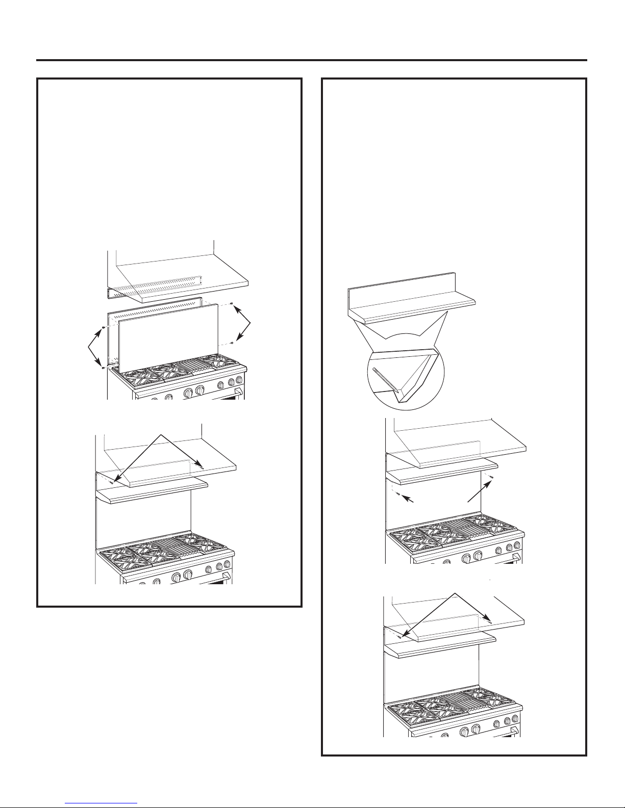
INSTALL COVER PANELS
See alternate method if side access is blocked.
• Hold the bottom cover over the bottom support
while driving one screw (provided) into each side.
• Place the top cover with shelf over the top wall
support. If you have access to the sides, secure
the panel with two screws on each side.
• Secure the top cover with shelf to the top
support with screws through the front of the panel,
at the top corners. Use one screw on each side.
Install
Cover Panel
Install
Screw
Screw
INSTALL COVER PANELS (cont.)
ALTERNATE METHOD: When side access is blocked
• Install bottom cover over the bottom support while
driving one screw into each side.
• Hold top cover in place while marking screw
locations, just below shelf support and onto bottom
cover.
• Remove the shelf and drill a 9/64" diameter
hole in the pencil-marked locations.
• Mount the top cover over the top support
and secure the front cover with screws through
the drilled holes on each side.
• Install screws through each top corner.
Mark Screw Locations
for Alternate Method
Install Corner Screws
Install Screw
on Each Side
Install Screw in Top Corner on Each Side
Shelf
14
DOWN
FOR OFF
NAT
LP
L
P
NAT
L
P
N
AT
N
AT
L
P
Installation Convert Natural Gas to LP Gas Operation
Instructions Convert LP Gas to Natural Gas Operation
2
WARNING: This conversion must
be performed by a qualified installer or gas supplier
in accordance with the manufacturer’s instructions
and all codes and requirements of the authority having
jurisdiction. Failure to follow instructions could result
in serious injury or property damage. The qualified
agency performing this work assumes responsibility
for the conversion.
WARNING: The rangetop, as shipped from
the factory, is set for use with its intended gas. If you
wish to use your rangetop with the alternate gas, you
must first replace the orifices and convert the pressure
regulator.
WARNING: The following adjustments must
be made before turning on the burner. Failure to do so
could result in serious injury. Be sure pressure regulator
has been conv
erted as described in S
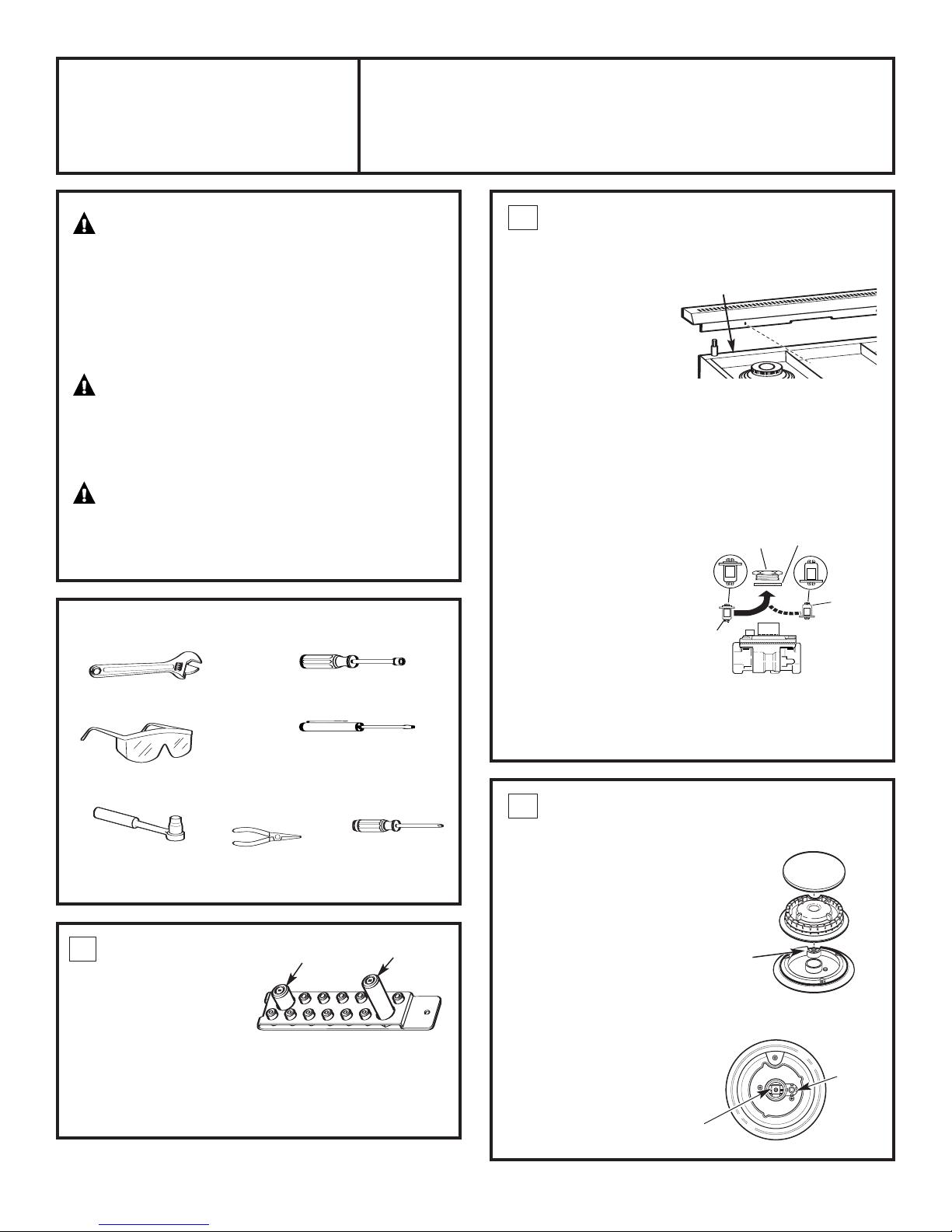
TOOLS YOU NEEDED FOR CONVERSION
tep 2.
CONVERT THE REGULATOR
Disconnect all electrical power at the main circuit
breaker or fuse box.
A. Remove the rear vent
trim (on ranges only)
to access the
regulator. The
Rangetop regulator is
on the left bottom
corner.
B. Shut off the gas supply by closing the manual shut-off
valve in the unit or at the wall.
C.
Convert the pressure regulator:
• Unscrew the cap with plunger.
• Place your thumb against flat side of the plunger and
press down to snap the plunger out of the cap.
• Carefully look at the plunger to locate the NAT
or LP position.
• Turn the
plunger
over so
that the
desired gas
is showing
near the
bottom.
Range Regulator
NAT. Position
Cap
Gasket
Plunger
LP Position
Crescent Wrench
Safety Glasses
1/2” Deepwell
Socket Wrench
1
ORIFICE HOLDER
Small Pliers
1/4” and 7mm Nutdrivers
Small Flat-Head Screwdriver
(2 to 2.4 mm or 3/32” tip size,
60 mm long)
Griddle
Orifice
The range orifice holder
is located behind the fr
ont
access panel at the bottom
of the range.
ner Orifices
The rangetop orifice holder
is located inside the range insulation cov
Additional orifices may be present. Use only the orifices
specified in the instr
uctions for your range or rangetop
Bur
er
.
Philips
Screwdriver
Grill
Orifice
.
Pressure Regulator
• Snap the plunger back into the cap.
• Screw the cap back onto the regulator.
3
CHANGE BURNER ORIFICES
INSTALLATION TIP: First remove all
eplacing them.
orifices and then star
t r
This will help to prevent the possibility
that some may not be replaced.
e the burner grates,
emov
A.R
burner caps and burner heads.
B. Loosen the top burner
orifices using a 7 mm
. Use small
er
nut driv
Burner
Head
Spark
Igniter
pliers to carefully lift out the orifices.
The main orifice is located
low in the center of the
burner, while the simmer
orifice is located higher
beside the center
of the burner.
Main
Orifice
Burner Cap
Burner Base
Simmer
Orifice
15
Installation Instructions for Gas Conversion
3
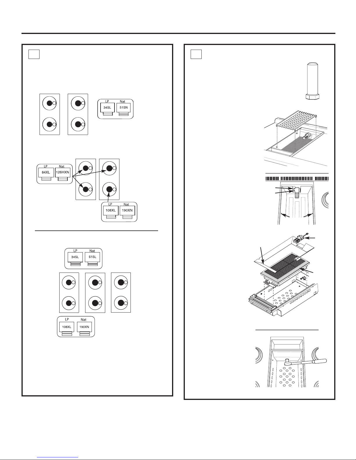
CHANGE BURNER ORIFICES (cont.)
IMPORTANT: Find your model number below. Read
each orifice label to identify and install them in the
exact locations shown.
ZDP304 SIMMER ORIFICES
A 34SL or 51SN orifice
will be used on all burners.
ZDP304 MAIN ORIFICES
Use a 108XL
or 190XN orifice
A 84XL or
126HXN orifice
will be used
on these three
burners.
for the right
front burner.
4
CHANGE GRILL ORIFICE
Locate the 1–1/2” long Grill orifice.
Select for your gas type. LP
—
.047, NAT—.067
A. Remove the grill cover,
grates and grate frame. Lift
the radiant baffle straight
up and off.
B. Remove the 2 hex
head screws from
the top of the igniter
• Remove one screw
.
Remove 2
hex head
screws
from each side of
the burner surround.
• Lift out the surround.
(if present)
Surround
Screws
ZDP364, ZDP366, ZDP484, ZDP486
SIMMER
ORIFICES
MAIN
ORIFICES
A. Return the unused orifices to the holder. Reattach
the holder and the instruction sheet with screw
in the original storage location.
B. Replace the burner heads, caps and top grates
On range models, r
eplace rear vent trim.
A 34SL or 51SN orifice
will be used on all
burners.
Use 108XL or
190XN orifices
for all burner
s.
C. Carefully push the
igniter aside and
Burner
Surround
Igniter
under
the burner
.
Do not pull or pinch
the wire.
Remove 4 burner
Burner
Assembly
attachment screws,
2 at the fr
at the back
ont and 2
. Slide the
burner assembly
toward the back and
out of the gas inlet
D. Use a 1/2" deep well
.
ont of Range
Fr
socket to remove
eplace the orifice .
and r
Reverse these
steps to re-assemble
the grill. Be sure to
.
place the unused
orifice in the holder
e use.
for possible f
utur
16
 Loading...