

Monogram WX08X10002, WX08X10006, WX08X10025, WX08X10015, ZFGB21HZSS Installation Instructions Manual

Installation
Instructions
Stainless Steel Free-Standing,
Drawer Freezer Refrigerator
monogram.com
31-46547
225D1974P007
Safety Information
CAUTION:
Due to the weight and size of this refrigerator, and to
reduce the risk of personal injury or damage to the
product – TWO PEOPLE ARE REQUIRED FOR PROPER
INSTALLATION.
PRUDENCE:
À cause du poids et de la taille de ce réfrigérateur et
pour réduire le risque de blessure et de dommages,
IL FAUT DEUX PERSONNES POUR FAIRE L’INSTALLATION
CORRECTEMENT.
WARNING:
• Use this appliance only for its intended pur pose.
• Immediately repair or replace electric service cords
that become frayed or damaged.
• Unplug the refrigerator before cleaning or making
repairs.
• Repairs should be made by a qualified service
technician.
AVERTISSEMENT:
• Il ne faut utiliser cet appareil que pour l’utilisation
appropriée.
• Réparer ou remplacer immédiatement tout cordon
électrique effiloché ou endommagé.
• Il faut débrancher le réfrigérateur avant le nettoyage
ou toute intervention.
• Les réparations doivent être faites par un technicien
qualifié.
For Monogram local service in your area,
call 1.800.444.1845.
For Monogram service in Canada,
call 1.800.561.3344
For Monogram Parts and Accessories,
call 1.800.626.2002.
www.monogram.com
2
BEFORE YOU BE GIN
Read these in struc tions completely and carefully.
• IM POR TANT– Save these instructions
for local inspector’s use.
• IM POR TANT– Observe all gov ern ing
codes and ordinances.
• Note to In stall er – Be sure to leave these
instructions with the Consumer.
• Note to Con sum er – Keep these instructions with
your Owner’s Manual for future reference.
WARNING:
This appliance must be properly ground ed. See
“Ground ing the Refrigerator,” page 4.
AVERTISSEMENT:
Cet appareil doit être correctement mis à la terre.
Consulter « Mise à la terre du réfrigérateur », page 4.
If you received a damaged refrigerator, you should
immediately contact your dealer or builder.
Skill Level – Installation of this refrigerator requires
basic me chan i cal, carpentry and plumbing skills.
Proper installation is the re spon si bil i ty of the installer.
Product failure due to improper installation is not
covered under the GE Appliance Warranty.
See the Owner’s Manual for warranty information.
CONTENTS
Planning Information
Product Dimensions and Clearances............................................3
The Installation Space ..........................................................................3
Installation Instructions
Tools, Hardware, Materials ..............................................................4
Grounding the Re frig er a tor ..............................................................4
Step 1, Measure Cabinet Opening ................................................5
Step 2, Install Anti-Tip Bracket ....................................................5-6
Step 3, Install the Refrigerator ........................................................7
Step 4, Remove the Freezer Drawers ......................................7-8
Step 5, Remove the Fresh Food Doors ........................................8
Step 6, Remove the Toekick ............................................................9
Step 7, Move the Refrigerator ........................................................9
Step 8, Replace the Freezer Drawers ..................................9-10
Step 9, Replace Fresh Food Doors ............................................11
Step 10, Install Water Line ............................................................11
Step 10A, RO Water Line ................................................................12
Step 11, Connect Water Supply ..................................................12
Step 12, Connect Power ..................................................................12
Step 13, Move Refrigerator Into Position ................................12
Step 14, Level Refrigerator ............................................................13
Step 15, Level Doors ..........................................................................13
Step 16, Install Toekick......................................................................14
Step 17, Start Icemaker ..................................................................14
Step 18, Temperature Controls ....................................................14
Planning Information
3
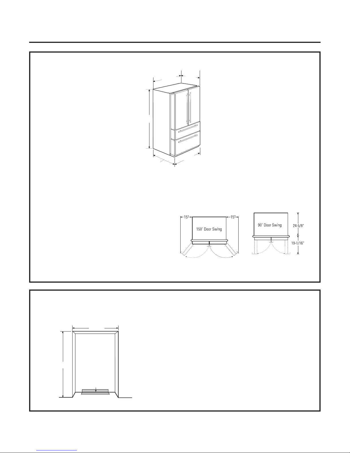
PRODUCT DIMENSIONS AND CLEARANCES
These Monogram free-standing refrigerators require the
following clearances for proper air circulation, plumbing
and electrical connections.
Air Circulation Clearances:
• 1/8" on each side
• 1/2" at the back side
Installation in a corner:
• Allow 4" clearance on each side to an adjacent wall for a
90° open ing and access to drawers.
• Allow 15" clearance to wall on each side for removal
of drawers.
69-5/8"
35-7/8"
Depth Including Handles
29-1/2" - Tubular Handles
30-1/4" - Professional Handles
27-1/2"
D
epth
35-7/8"
C
ase Width
THE INSTALLATION SPACE
The opening width must be at least 36".
Water And Electrical Locations
The opening must be prepared with the electrical and
water supply located as shown.
Additional Specifications
• A 115 volt 60Hz., 15 or 20 amp power supply is required.
An individual properly grounded branch circuit or circuit
breaker is recommended. Install a properly grounded
3-prong electrical receptacle recessed into the back wall.
NOTE: GFI (ground fault interrupter) is not recommended.
• The cold water line can enter the opening through the
floor or through an adjacent cabinet, as close to the back
wall as possible. The water line should be GE
SmartConnect™ Refrigerator Tubing or 1/4" O.D. copper
tubing between the cold water line and water con nec tion
location at the rear of the re frig er a tor. Installation of an
easily accessible shut off valve in the water line is
rec om mend ed.
70" min.
36" min.
Electrical
Area
Wall View
Water Supply
Installation Instructions
4
TOOLS REQUIRED
• Adjustable wrench
• 3/8" and 5/15" socket ratchet/driver
• Phillips head screwdriver
• 3/32", 1/8", 1/4" Allen wrenches
• 1/8" Drill bit and electric or hand drill
• Tape measure
• Pencil
• Wire cutters
• 1/4" Nut driver
• Level
MATERIALS REQUIRED
• 1/4" O.D. compression nut and 2 ferrules (sleeves)
OR GE SmartConnect™Refrigerator Tubing Kits
FLOORING
For proper installation, this refrigerator must be placed on
a level surface of hard material that is at the same height
as the rest of the flooring. This surface should be strong
enough to support a fully loaded refrigerator.
IMPORTANT NOTE: Protect the finish of the flooring.
Cut a large section of the cardboard carton and place
under the refrigerator where you are working.
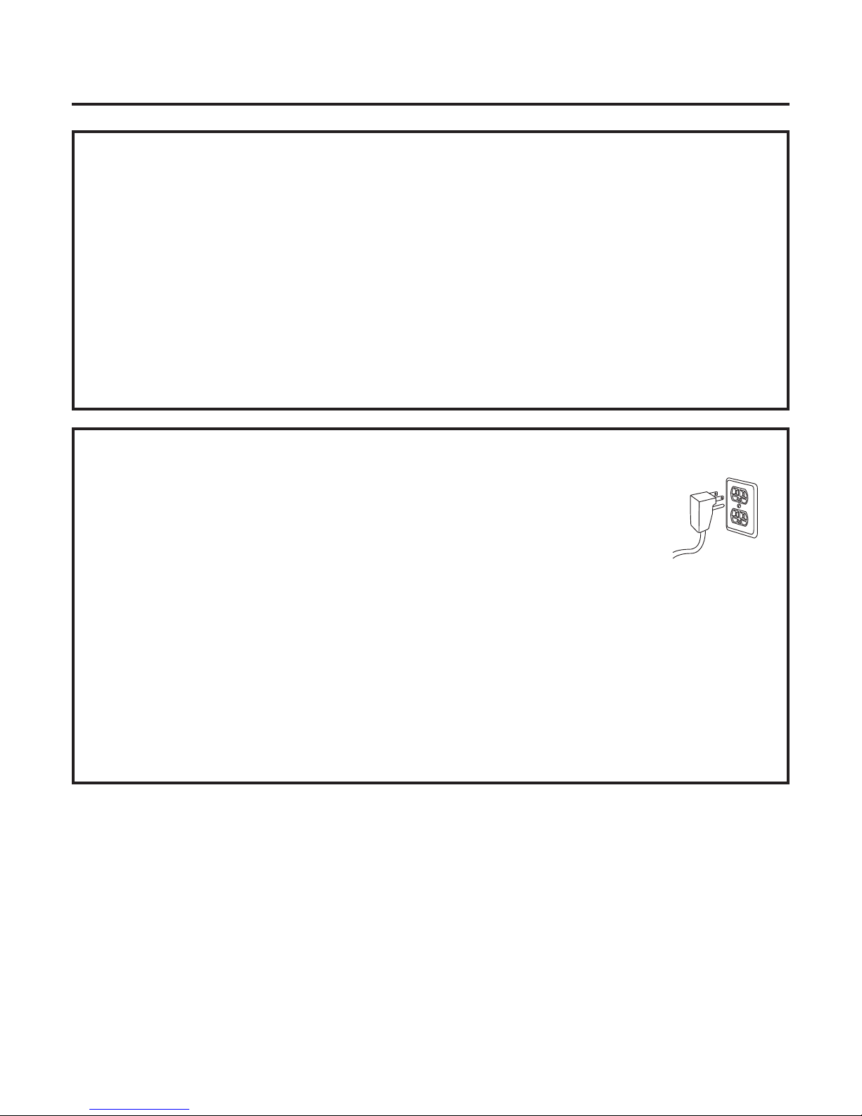
GROUNDING THE REFRIGERATOR
IMPORTANT – (Please read carefully)
FOR PERSONAL SAFETY, THIS APPLIANCE MUST BE
PROPERLY GROUNDED.
The power cord of this appliance is equipped with
a 3-prong (grounding) plug which mates with a
standard 3-prong (grounding) wall receptacle to
minimize the possibility of electric shock hazard
from this appliance.
Have the wall outlet and circuit checked by a
qualified elec tri cian to make sure the outlet is
properly grounded.
Where a standard 2-prong wall outlet is en coun tered,
it is your personal responsibility and obligation to
have it replaced with a properly grounded 3-prong
wall outlet.
DO NOT, UNDER ANY
CIRCUMSTANCES, CUT
OR REMOVE THE THIRD
(GROUND) PRONG
FROM THE POWER CORD.
DO NOT USE AN ADAPTER PLUG TO CONNECT
THE REFRIGERATOR TO A 2-PRONG OUTLET.
DO NOT USE AN EXTENSION CORD WITH
THIS APPLIANCE.
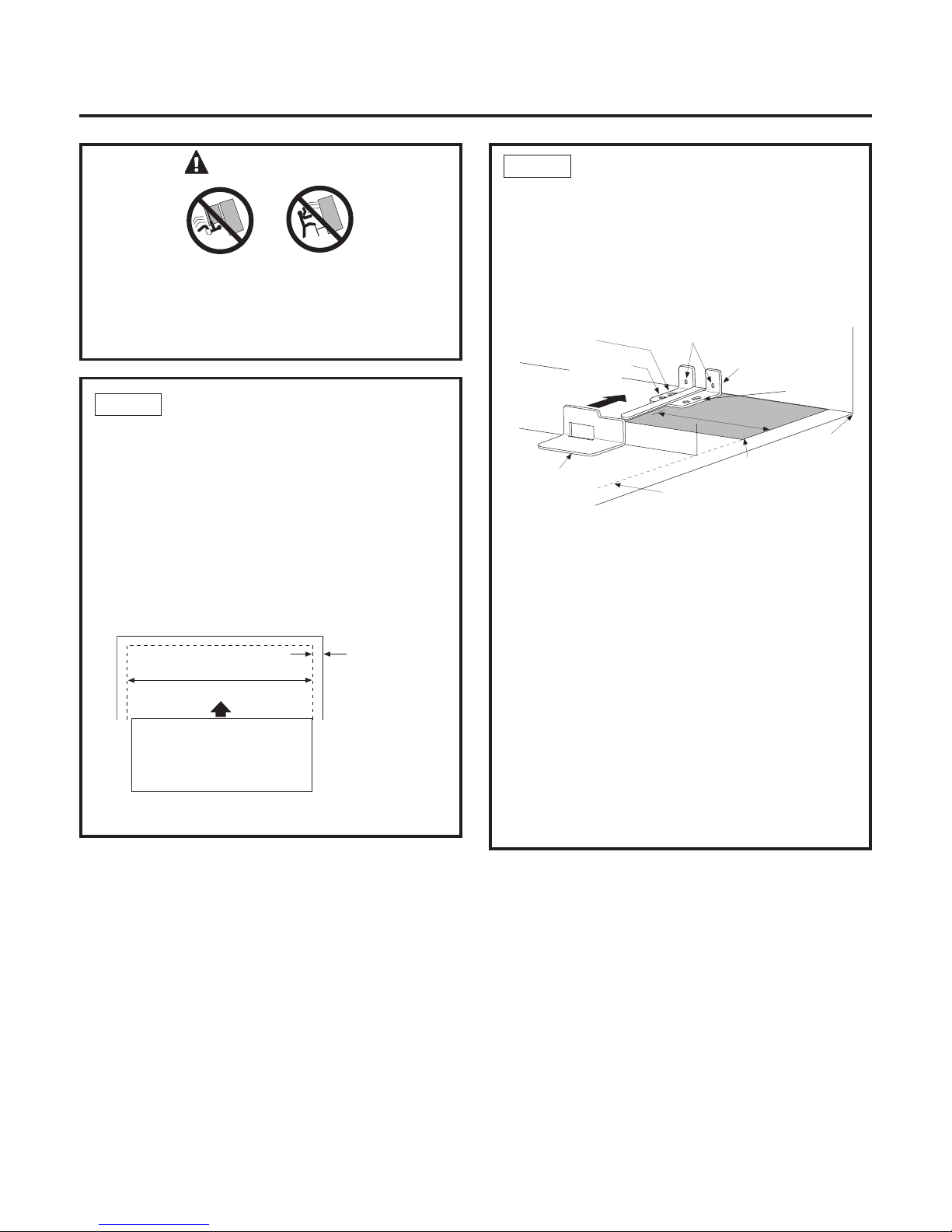
WARNING
Under certain circumstances, this refrigerator
can tip forward.
Injury to persons can result.
Install Anti-Tip Bracket packed with this refrigerator.
Installation Instructions
5
STEP 2 LOCATE ANTI-TIP BRACKET
A. Place the anti-tip floor bracket locator template
(included inside the anti-tip kit) onto the floor up
against the rear wall, within W, and in line with the
desired location of the RH side of the refrigerator
(see Figure 1).
B. Place the anti-tip floor bracket onto the locator
template with its RH floor holes lined up with the
floor holes indicated on the template sheet, approximately 7-1/4” from the edge of the sheet or the RH
side of the refrigerator.
C. Hold down in position and use the anti-tip floor
bracket as a template for marking the holes based
upon your configuration and type of construction
as shown in Step 3. Mark the hole locations with
a pencil, nail or awl.
Floor - Concrete
(2 Holes)
Floor - Wood
(2 Holes)
Base
Bracket on
the Refrigerator
RH Holes
7 1⁄4”
Rear RH
Corner of
Cabinet Wall
RH Side of
Refrigerator
Locator
Template
Sheet
2 Wall Holes
Floor Bracket
to Install
Figure 1 – Installation Overview
NOTE: It is REQUIRED to use at least 2 screws to
mount the floor bracket (one on each side of the
anti-tip floor bracket). Both must be into either
the wall or the floor. Figure 2 indicates all the
acceptable mounting configurations for screws.
Identify the screw holes on the anti-tip floor bracket
for your configuration.
STEP 1 MEASURE CABINET OPENING
AVAILABLE VS. REFRIGERATOR
WIDTH
Measure width of cabinet opening where refrigerator
will be placed, W.
Be sure to account for any countertop overhang,
baseboard thickness and any clearance desired.
Width, W, should not be less than 36 inches.
The refrigerator will be placed approximately
in the middle of this opening.
Rear Wall
REFRIGERATOR
RH Side
Baseboard
Thickness
or Countertop
Overhang
(Whichever
is Greater) Plus
Any Desired
Clearance
Front
W
 Loading...