

Page 1
Installation
Electric Indoor Pizza Oven
Instructions
ZEP30
If you have questions, call GE Appliances at 800.GE.CARES (800.432.2737)
or visit our website at: GEAppliances.com.
BEFORE YOU BEGIN
Read these instructions carefully and completely.
• IMPORTANT — Save these instructions
for local inspector’s use.
• IMPORTANT — Observe all governing
codes and ordinances.
• Note to Installer – Be sure to leave these
instructions with the consumer.
• Note to Consumer – Keep these instructions for
future reference.
• Proper installation is the responsibility of the
installer and product failure due to improper
installation is NOT covered under warranty.
• Note – This appliance must be properly grounded.
• ATTENTION INSTALLER
All electric wall ovens must be hard wired (direct
wired) into an approved junction box. A plug and
receptacle is NOT permitted on these products.
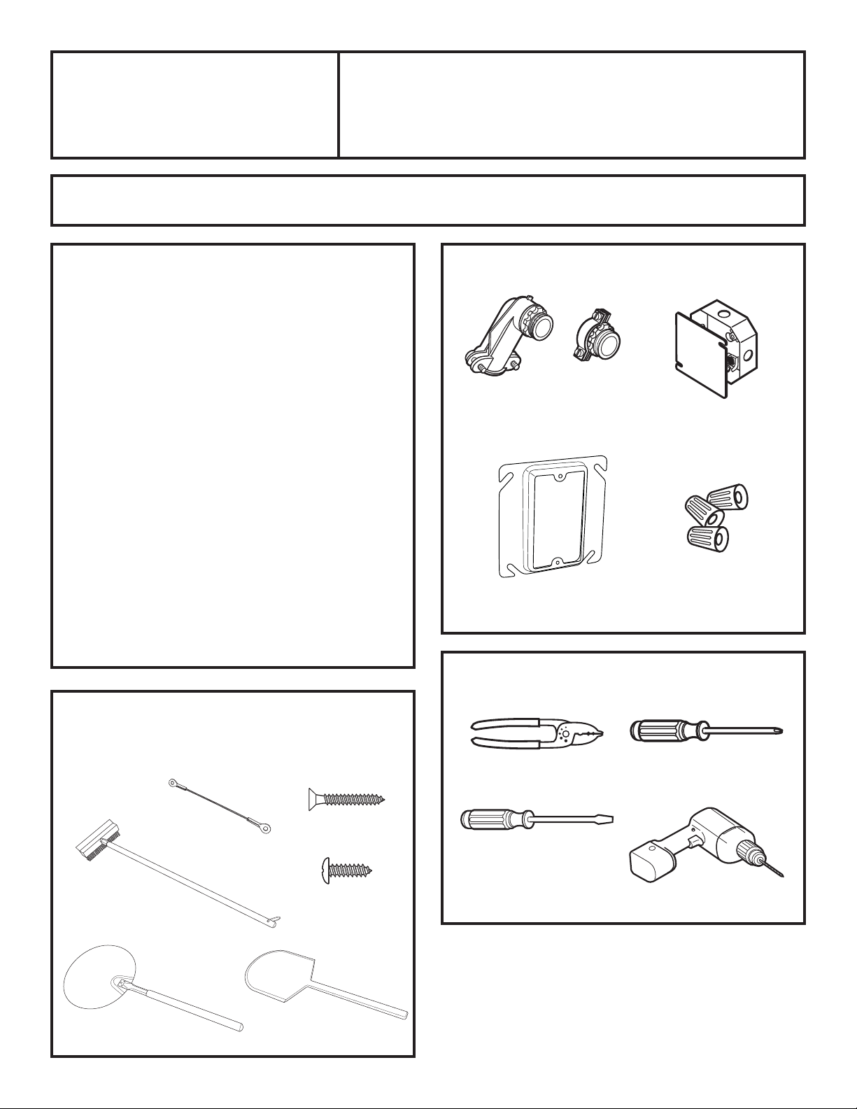
MATERIALS NEEDED
Option 2
Option 1
Strain Relief Clamp
for 1/2” conduit
Plaster Ring
(Option 1)
Junction Box
(1 1/2 Depth Max.)
Wire Nuts
PARTS INCLUDED
(Appearance will vary)
Tether
Brush
Metal Peel
1” Drywall Screw
5/8” Phillips
Case Screw
Wooden Peel
TOOLS NEEDED
Wire Strippers
Flathead
Screwdriver
Phillips #2
Screwdriver
Drill and 1/8” drill bit
31-11062 12-16 GEA
Page 2
Installation Instructions
IMPORTANT SAFETY INSTRUCTIONS
FOR YOUR SAFETY
• Be sure your oven is installed properly by a
qualified installer or service technician.
• Be sure the oven is securely installed in a cabinet
that is firmly attached to the house structure. Never
allow anyone to climb, sit, stand or hang on the oven.
• Make sure the cabinets and wall coverings around
the oven can withstand the temperatures (up to
200°F [93.3°C]) generated by the oven.
WARNING
oven supply line must be shut off while line
connections are being made. Failure to do so
could result in serious injury or death.
The electrical power to the
ELECTRICAL REQUIREMENTS
This appliance must be supplied with the proper
voltage and frequency, and connected to an
individual, properly grounded branch circuit, protected
by a circuit breaker or fuse. See the rating plate
located on the bottom of the front panel to determine
the rating of the product. Use the chart below to
determine the minimum recommended dedicated
circuit protection.
KW Rating 240V KW Rating 208V
9.7 KW–12.0 KW 8.4 KW–10.4 KW 50 Amp
Required Circuit
Size (Dedicated)
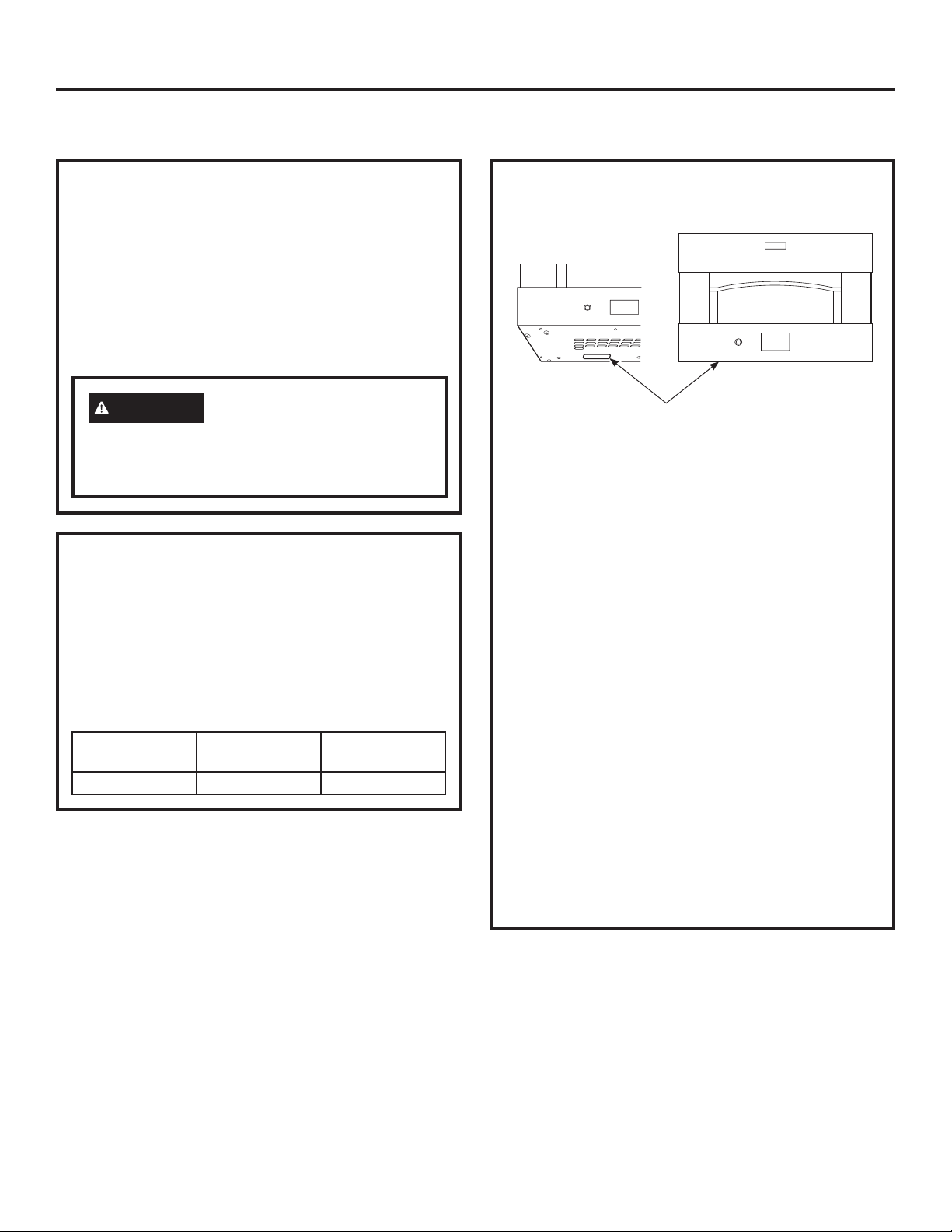
ELECTRICAL REQUIREMENTS
Rating plate is located on the bottom of the front panel.
Rating Plate Location
We recommend you have the electrical wiring
and hookup of your oven connected by a qualified
electrician. After installation, have the electrician show
you how to disconnect power from the range.
Check with your local utilities for electrical codes
which apply in your area. Failure to wire your oven
according to governing codes could result in a
hazardous condition. If there are no local codes,
your oven must be wired and fused to meet the
requirements of the National Electrical Code, NFPA
No. 70–Latest Edition, available from the National
Fire Protection Association.
Effective January 1, 1996, the National Electrical
Code requires that new, but not existing, construction
utilize a four-conductor connection to an electric oven.
When installing an electric oven in new construction,
a mobile home, recreational vehicle or an area where
local codes prohibit grounding through the neutral
conductor, follow the instructions in the section on
NEW CONSTRUCTION AND FOUR-CONDUCTOR
BRANCH CIRCUIT CONNECTION.
You must use a single-phase 120/208 VAC or 120/240
VAC, 60 hertz electrical system. If you connect
to aluminum wiring, properly installed connectors
approved for use with aluminum wiring must be used.
2 31-11062
Page 3
Installation Instructions
PRE-INSTALLATION CHECKLIST
ALL INSTALLATION INFORMATION ON THE
FOLLOWING PAGES IS TO BE USED FOR
ELECTRIC INDOOR PIZZA OVEN INSTALLATION!
Remove packaging materials and literature pack.
Bef
Bef
Be
Be
Be
Be
Bef
Bef
Bef
Bef
Bef
Bef
f
f
f
f
o
o
ore
ore
ore
ore
ore
ore
ore
ore
ore
ore
r
r
e
e
yo
yo
yo
yo
you
you
you
you
yo
yo
yo
yo
u
u
u
u
u
u
u
u
IM
IM
IM
IM
IM
IM
IM
IM
IM
IM
IM
IM
Installation
Electric Indoor Pizza Oven
be
be
be
be
be
be
beg
beg
be
be
be
be
PO
PO
PO
PO
PO
PO
PO
PO
PO
PO
PO
PO
gi
gi
g
g
g
g
g
g
g
g
i
i
i
i
i
i
i
i
i
i
R
R
R
R
RT
RT
R
R
R
R
RT
RT
n
n
n
n
n
n
n
n
n-
n-
n-
n-
T
T
T
T
T
T
T
T
-
-
-
-
-
-
-
-
Re
Re
Re
Re
Re
Re
Re
Re
Re
Re
Re
Re
ANT-
ANT-
ANT-
ANT-
AN
AN
ANT-
ANT-
ANT-
ANT-
AN
AN
ad
ad
ad
ad
ad
ad
ad
ad
ad
ad
ad
ad
IM
IM
IM
IM
IM
IM
IM
IM
IM
IM
IM
IM
T-
T-
T-
T-
PO
PO
PO
PO
PO
PO
PO
PO
PO
PO
PO
PO
th
th
th
th
th
th
th
th
th
th
th
th
Save
Save
Save
Save
Save
Save
Save
Save
Save
Save
Save
Save
es
es
es
es
es
es
es
es
es
es
es
es
RT
RT
RT
RT
R
R
R
R
RT
RT
RT
RT
T
T
T
T
e in
e in
e
e
e
e
e
e
e
e
e
e
AN
AN
AN
AN
ANT-
ANT-
ANT-
ANT-
AN
AN
AN
AN
thes
thes
thes
thes
th
th
t
t
t
t
t
t
in
in
in
in
in
in
in
in
in
in
hes
hes
hes
hes
h
h
ZEP30
Instructions
No
No
No
No
No
No
No
No
No
No
No
No
es
es
es
es
s
s
s
s
s
s
stru
stru
s
s
s
s
T-
T-
T-
T-
T-
T-
T-
T-
t
t
t
t
t
t
t
t
t
t
ruct
ruct
ruct
ruct
ru
ru
ru
ru
ru
ru
e
e
e
e
e
e
e
e
e
e
e
e
te
te
te
te
te
te
te
te
te
te
te
te
OB
OB
OB
OB
OB
OB
OB
OB
OB
OB
OB
OB
i
i
i
i
i
i
i
i
i
i
i
i
ct
ct
ct
ct
ct
ct
ct
ct
n
n
n
n
n
n
n
n
n
n
n
n
to
to
to
to
to
to
to
to
to
to
to
to
s
s
s
s
s
s
s
s
s
s
s
s
SER
SER
SER
SER
SER
SER
SER
SER
SER
SER
SER
SER
i
i
io
io
io
io
i
i
io
io
io
io
o
o
o
o
t
t
t
t
t
t
t
t
t
t
t
t
ruct
ruct
ruct
ruct
ru
ru
ructi
ructi
ruct
ruct
ruct
ruct
In
In
In
In
In
In
Inst
Inst
I
I
I
I
ns
ns
ns
ns
ns
ns
ns
ns
ns
ns
ns
ns
n
n
n
n
V
V
V
V
V
V
V
V
V
V
V
V
ct
ct
stal
stal
stal
stal
s
s
s
s
s
s
OW
OW
OW
OW
OW
OW
OW
OW
OW
OW
OW
OW
t
t
t
t
t
t
co
co
co
co
co
co
co
co
co
co
co
co
E
E
E
E
E
E
E
E
E
E
E
E
al
al
al
al
alle
alle
alle
alle
i
i
i
i
i
i
i
i
i
i
o
o
o
o
o
o
o
o
o
o
o
o
A
A
A
A
A
A
A
A
A
A
A
A
m
m
m
m
m
m
mple
mple
mple
mple
m
m
le
le
le
le
le
le
le
le
n
n
n
n
n
n
n
n
n
n
n
n
NE
NE
NE
NE
NE
NE
NE
NE
NE
NE
NE
NE
LL
LL
LL
LL
LL
LL
LL
LL
LL
LL
LL
LL
s
s
s
s
s
s
s
s
s
s
s
s
r-
r-
r-
r-
r-
r-
r-
r-
r-
r-
r-
r-
ple
ple
ple
ple
p
p
p
p
for
for
for
for
fo
fo
for
for
for
for
fo
fo
R-
R-
R-
R-
R-
R-
l
l
l
l
R-
R-
R-
R-
R-
R-
GO
GO
GO
GO
GO
GO
GO
GO
GO
GO
GO
GO
Be
Be
Be
Be
Be
Be
Be
Be
Be
Be
Be
Be
ete
ete
ete
ete
r
r
r
r
te
te
te
te
te
te
te
te
K
K
K
K
K
K
K
K
K
K
K
K
lo
lo
lo
lo
lo
lo
lo
lo
lo
lo
lo
lo
su
su
su
su
su
su
su
su
s
s
s
s
VE
VE
VE
VE
VE
VE
VE
VE
VE
VE
VE
VE
ly
ly
ly
ly
ly
ly
ly
ly
ly
ly
ly
ly
No
No
No
No
No
No
No
No
No
No
No
No
e
e
e
e
e
e
e
e
e
e
e
e
u
u
u
u
ca
ca
ca
ca
cal
cal
ca
ca
ca
ca
ca
ca
e
e
e
e
e
e
e
e
ep
ep
ep
ep
an
an
an
an
an
an
an
an
an
an
an
an
re
re
re
re
re
re
re
re
re
re
re
re
RN
RN
RN
RN
RN
RN
RN
RN
RN
RN
RN
RN
p
p
p
p
p
p
p
p
If you have questions, call GE Appliances at 800.GE.CARES (800.432.2737)
te
te
te
te
te
te
te
te
te
te
te
te
l
l
l
l
l
l
l
l
l
l
th
th
th
th
thes
thes
th
th
th
th
th
th
in
in
in
in
in
in
in
in
in
in
in
in
to
to
to
to
to
to
to
to
to
to
to
to
d
d
d
d
d
d
d
d
d
d
d
d
-
-
-
-
-
-
-
-
-
-
-
-
IN
IN
IN
IN
IN
IN
IN
IN
IN
IN
IN
IN
Th
Th
Th
Th
Th
Th
Th
Th
Th
Th
This
This
sp
sp
sp
sp
sp
sp
sp
sp
sp
sp
sp
sp
es
es
es
es
es
es
es
es
es
es
ca
ca
care
care
care
care
ca
ca
ca
ca
ca
ca
le
le
le
le
le
le
le
le
le
le
le
le
G
G
G
G
G
G
G
G
G
G
G
G
e in
e in
e in
e in
e in
e in
e in
e in
e in
e in
e in
e in
ec
ec
ec
ec
ec
ec
ec
ec
ec
ec
ec
ec
is
is
is
is
is
is
is
is
is
is
re
re
re
re
re
re
re
re
av
av
av
av
av
av
av
av
av
av
av
av
CODE
CODE
CODES
CODES
CODES
CODES
CODE
CODE
CO
CO
CO
CO
a
a
a
a
a
a
a
a
a
a
a
a
fu
fu
fu
fu
fu
fu
fu
fu
fu
fu
fu
fu
t
t
t
t
t
t
t
t
t
t
t
t
e t
e t
e t
e t
e t
e t
e t
e t
e
e
e
e
or visit our website at: GEAppliances.com.
o
o
o
o
or'
or'
or'
or'
or'
or'
o
o
pplian
pplian
ppliance
ppliance
ppliance
ppliance
pplian
pplian
ppli
ppli
ppli
ppli
stru
stru
stru
stru
st
st
s
s
s
s
s
s
DES
DES
DES
DES
lly
lly
lly
lly
lly
lly
lly
lly
lly
lly
lly
lly
th
th
th
th
r
r
r
r
r
r
t
t
t
t
t
t
hes
hes
h
h
h
h
hes
hes
'
'
'
'
'
'
ructi
ructi
ru
ru
ru
ru
ructio
ructio
s
s
s
s
s
s
s
s
s
s
s
s
.
.
.
.
.
.
.
.
.
.
.
.
es
es
es
es
es
es
es
es
S
S
S
S
an
an
an
an
us
us
us
us
us
us
us
us
us
us
us
us
ct
ct
ct
ct
ct
ct
ct
ct
AN
AN
AND
AND
AND
AND
AN
AN
AND
AND
AND
AND
e
e
e
e
e
e
e
e
e
e
e
e
i
i
i
i
i
i
i
i
e.
e.
e.
e.
e.
e.
e.
e.
e.
e.
e.
e.
ce
ce
ce
ce
ce
ce
ce
ce
o
o
o
o
o
o
o
o
o
o
i
i
i
i
in
in
i
i
i
i
i
i
n
n
n
n
n
n
n
n
n
n
ns
ns
ns
ns
ns
ns
ns
ns
ns
ns
ns
ns
D OR
D OR
D OR
D OR
s
s
s
s
s
s
st
st
stru
stru
stru
stru
mu
mu
mu
mu
mu
mu
mu
mu
mu
mu
mu
mu
t
t
t
t
t
t
OR
OR
OR
OR
OR
OR
OR
OR
f
f
f
f
f
f
f
f
f
f
f
f
ru
ru
ru
ru
ruct
ruct
ruct
ruct
o
o
o
o
or
or
o
o
o
o
o
o
s
s
s
s
s
s
st
st
st
st
st
st
r
r
r
r
r
r
r
r
r
r
ct
ct
ct
ct
ct
ct
ct
ct
DI
DI
DI
DI
DI
DI
DI
DI
DI
DI
DI
DI
t
t
t
t
t
t
fu
fu
fu
fu
fu
fu
fu
fu
fu
fu
fu
fu
io
io
io
io
ions
ions
io
io
io
io
io
io
be
be
be
be
b
b
be
be
be
be
be
be
AN
AN
AN
AN
AN
AN
ANCE
ANCE
ANCE
ANCE
ANCE
ANCE
e
e
tu
tu
tu
tu
tu
tu
tu
tu
tu
tu
tu
tu
n
n
n
n
n
n
ns
ns
ns
ns
p
p
p
p
p
p
p
p
p
p
pr
pr
s
s
s
s
s
s
re
re
re
re
re
re
re re
re re
re re
re re
r
r
CE
CE
CE
CE
CE
CE
e
e
r
r
r
r
r
r
r
r
r
r
wi
wi
wi
wi
wi
wi
wi
wi
wi
wi
wi
wi
oper
oper
oper
oper
oper
oper
o
o
o
o
o
o
re
re
re
re
re
re
re
re
S
S
S
S
S.
S.
S.
S.
S.
S.
S.
S.
p
p
p
p
per
per
th
th
th
th
th
th
th
th
th
th
th
th
.
.
.
.
er
er
er
er
fer
fer
fer
fer
fer
fer
fer
fer
fer
fer
fer
fer
BEFORE YOU BEGIN
MATERIALS NEEDED
the
the
th
th
th
th
th
th
th
th
the
the
ly
ly
ly
ly
ly
ly
ly
ly
ly
ly
ly
ly
e
e
e
e
e
e
e
e
e
e
e
e
e
e
e
e
e
e
e
e
n
n
n
n
n
n
n
n
n
n
n
n
groun
groun
groun
groun
groun
groun
groun
groun
groun
groun
grounded
grounded
c
c
c
c
c
c
c
c
c
c
c
c
co
co
cons
cons
cons
cons
co
co
co
co
co
co
e.
e.
e.
e.
e.
e.
e.
e.
e.
e.
e.
e.
FO
FO
FO
FO
ns
ns
ns
ns
ns
ns
ns
ns
R
R
R
R
u
u
u
u
u
u
u
u
u
u
u
u
ded
ded
ded
ded
ded
ded
ded
ded
ded
ded
Read these instructions carefully and completely.
YOUR
YOUR
YOUR
YOUR
m
m
m
m
m
m
mer
mer
mer
mer
mer.
mer.
er
er
er
er
er
er
(if
(if
(if
(if
(if
(if
(if
(if
(if
(if
(if
(if
.
.
.
.
.
.
.
.
.
.
a
a
a
a
a
a
a
a
a
a
a
a
SAFE
SAFE
SAFE
SAFE
ppli
ppli
ppli
ppli
ppli
ppli
pplic
pplic
pplic
pplic
pplic
pplic
c
c
c
c
c
c
TY
TY
TY
TY
ab
ab
ab
ab
able
able
able
able
able
able
able
able
Bef
Bef
Bef
Bef
le
le
le
le
ore
ore
ore
ore
IMPORTANT — Save these instructions
•
).
).
).
).
).
).
).
).
).
).
).
).
yo
yo
yo
yo
u
u
u
u
i
i
i
i
n
n
n
n
for local inspector’s use.
be
be
be
be
str
str
str
str
g
g
g
g
u
u
u
u
in-
in-
in-
in-
ct
ct
ct
ct
R
R
R
R
io
io
io
io
e
e
e
e
ns
ns
ns
ns
ad
ad
ad
ad
car
car
car
car
co
co
co
co
th
th
th
th
e
e
e
e
fu
fu
fu
fu
mple
mple
mple
mple
es
es
es
es
Option 2
lly
lly
lly
lly
•
IMPORTANT — Observe all governing
e
e
e
e
.
.
.
.
te
te
te
te
IM
IM
IM
IM
Option 1
ly
ly
ly
ly
P
P
P
P
a
a
a
a
O
O
O
O
codes and ordinances.
n
n
n
n
RT
RT
RT
RT
d
d
d
d
AN
AN
AN
AN
E
E
E
E
LE
LE
LE
LE
in
in
in
in
Strain Relief Clamp
T-
T-
T-
T-
C
C
C
C
st
st
st
st
Sa
Sa
Sa
Sa
TR
TR
TR
TR
ruct
ruct
ruct
ruct
• Note to Installer – Be sure to leave these
Junction Box
ve
ve
ve
ve
IC
IC
IC
IC
for 1/2” conduit
io
io
io
io
AL
AL
AL
AL
th
th
th
th
ns
ns
ns
ns
IMPO
IMPO
IMPO
IMPO
es
es
es
es
(1 1/2 Depth Max.)
RE
RE
RE
RE
instructions with the consumer.
fo
fo
fo
fo
e
e
e
e
QUIR
QUIR
QUIR
QUIR
r lo
r lo
r lo
r lo
RT
RT
RT
RT
Bef
Bef
Bef
Bef
ca
ca
ca
ca
ANT-
ANT-
ANT-
ANT-
E
E
E
E
M
M
M
M
l
l
l
l
ore
ore
ore
ore
GO
GO
GO
GO
in
in
in
in
E
E
E
E
• Note to Consumer – Keep these instructions for
N
N
N
N
sp
sp
sp
sp
OB
OB
OB
OB
VE
VE
VE
VE
yo
yo
yo
yo
TS
TS
TS
TS
e
e
e
e
RN
RN
RN
RN
c
c
c
c
SER
SER
SER
SER
u
u
u
u
t
t
t
t
in
in
in
in
or's
or's
or's
or's
be
be
be
be
future reference.
IN
IN
IN
IN
st
st
st
st
VE
VE
VE
VE
No
No
No
No
gin-
gin-
gin-
gin-
ru
ru
ru
ru
G
G
G
G
u
u
u
u
ct
ct
ct
ct
AL
AL
AL
AL
C
C
C
C
s
s
s
s
t
t
t
t
e
e
e
e
e
e
e
e
ODES
ODES
ODES
ODES
Re
Re
Re
Re
ions
ions
ions
ions
.
.
.
.
L
L
L
L
to
to
to
to
ad
ad
ad
ad
ca
ca
ca
ca
In
In
In
In
• Proper installation is the responsibility of the
co
co
co
co
r
r
r
r
t
t
t
t
st
st
st
st
e
e
e
e
AN
AN
AN
AN
th
th
th
th
h
h
h
h
fu
fu
fu
fu
mple
mple
mple
mple
al
al
al
al
es
es
es
es
es
es
es
es
D
D
D
D
lly
lly
lly
lly
le
le
le
le
e
e
e
e
e in
e in
e in
e in
r
r
r
r
OR
OR
OR
OR
.
.
.
.
installer and product failure due to improper
-
-
-
-
te
te
te
te
IM
IM
IM
IM
Be
Be
Be
Be
st
st
st
st
DIAN
DIAN
DIAN
DIAN
ly
ly
ly
ly
PO
PO
PO
PO
ru
ru
ru
ru
an
an
an
an
su
su
su
su
OW
OW
OW
OW
ct
ct
ct
ct
re
re
re
re
RT
RT
RT
RT
d
d
d
d
installation is NOT covered under warranty.
CE
CE
CE
CE
io
io
io
io
NE
NE
NE
NE
to
to
to
to
AN
AN
AN
AN
ns
ns
ns
ns
S.
S.
S.
S.
R-
R-
R-
R-
in
in
in
in
le
le
le
le
T-
T-
T-
T-
wi
wi
wi
wi
K
K
K
K
st
st
st
st
av
av
av
av
Save
Save
Save
Save
f
f
f
f
e
e
e
e
th
th
th
th
r
r
r
r
or
or
or
or
e
e
e
e
uct
uct
uct
uct
ep
ep
ep
ep
• Note – This appliance must be properly grounded.
th
th
th
th
fu
fu
fu
fu
ions
ions
ions
ions
th
th
th
th
e
e
e
e
th
th
th
th
tu
tu
tu
tu
es
es
es
es
con
con
con
con
IM
IM
IM
IM
e
e
e
e
r
r
r
r
e
e
e
e
s
s
s
s
e
e
e
e
f
f
f
f
Wire Nuts
e
e
e
e
re
re
re
re
PO
PO
PO
PO
o
o
o
o
No
No
No
No
in
in
in
in
s
s
s
s
r lo
r lo
r lo
r lo
u
u
u
u
fe
fe
fe
fe
stru
stru
stru
stru
RT
RT
RT
RT
mer
mer
mer
mer
te
te
te
te
ren
ren
ren
ren
ca
ca
ca
ca
AN
AN
AN
AN
-
-
-
-
ct
ct
ct
ct
Th
Th
Th
Th
l
l
l
l
.
.
.
.
c
c
c
c
GO
GO
GO
GO
i
i
i
i
T-
T-
T-
T-
i
i
i
i
n
n
n
n
e.
e.
e.
e.
o
o
o
o
•
ATTENTION INSTALLER
i
i
i
i
s
s
s
s
s
s
s
s
ns
ns
ns
ns
Plaster Ring
p
p
p
p
OB
OB
OB
OB
VE
VE
VE
VE
a
a
a
a
p
p
p
p
e
e
e
e
rop
rop
rop
rop
pplian
pplian
pplian
pplian
RN
RN
RN
RN
c
c
c
c
SER
SER
SER
SER
t
t
t
t
or's
or's
or's
or's
er
er
er
er
IN
IN
IN
IN
(Option 1)
V
V
V
V
ly
ly
ly
ly
No
No
No
No
G
G
G
G
E
E
E
E
ce
ce
ce
ce
u
u
u
u
All electric wall ovens must be hard wired (direct
g
g
g
g
C
C
C
C
A
A
A
A
s
s
s
s
te
te
te
te
round
round
round
round
e.
e.
e.
e.
mu
mu
mu
mu
O
O
O
O
LL
LL
LL
LL
Be
Be
Be
Be
to
to
to
to
D
D
D
D
st
st
st
st
f
f
f
f
E
E
E
E
ore
ore
ore
ore
Inst
Inst
Inst
Inst
S
S
S
S
wired) into an approved junction box. A plug and
be
be
be
be
ed
ed
ed
ed
AND
AND
AND
AND
th
th
th
th
yo
yo
yo
yo
al
al
al
al
es
es
es
es
(
(
(
(
if
if
if
if
le
le
le
le
u
u
u
u
e
e
e
e
i
i
i
i
a
a
a
a
r-
r-
r-
r-
OR
OR
OR
OR
n
n
n
n
be
be
be
be
pplica
pplica
pplica
pplica
i
i
i
i
receptacle is NOT permitted on these products.
st
st
st
st
n
n
n
n
Be
Be
Be
Be
stru
stru
stru
stru
D
D
D
D
gi
gi
gi
gi
ruct
ruct
ruct
ruct
I
I
I
I
su
su
su
su
ANCE
ANCE
ANCE
ANCE
n-
n-
n-
n-
OW
OW
OW
OW
ct
ct
ct
ct
ble
ble
ble
ble
R
R
R
R
r
r
r
r
io
io
io
io
e
e
e
e
e
e
e
e
i
i
i
i
NE
NE
NE
NE
ns
ns
ns
ns
o
o
o
o
ad
ad
ad
ad
to
to
to
to
ca
ca
ca
ca
).
).
).
).
ns
ns
ns
ns
S.
S.
S.
S.
R-
R-
R-
R-
comple
comple
comple
comple
re
re
re
re
le
le
le
le
TOOLS NEEDED
the
the
the
the
w
w
w
w
K
K
K
K
fu
fu
fu
fu
av
av
av
av
i
i
i
i
f
f
f
f
eep
eep
eep
eep
th
th
th
th
s
s
s
s
lly
lly
lly
lly
or
or
or
or
e
e
e
e
e
e
e
e
t
t
t
t
.
.
.
.
fu
fu
fu
fu
h
h
h
h
te
te
te
te
th
th
th
th
IM
IM
IM
IM
e con
e con
e con
e con
tu
tu
tu
tu
ly
ly
ly
ly
es
es
es
es
P
P
P
P
r
r
r
r
an
an
an
an
e
e
e
e
O
O
O
O
e in
e in
e in
e in
r
r
r
r
R
R
R
R
No
No
No
No
s
s
s
s
d
d
d
d
e
e
e
e
u
u
u
u
T
T
T
T
fe
fe
fe
fe
st
st
st
st
ANT-
ANT-
ANT-
ANT-
mer.
mer.
mer.
mer.
te
te
te
te
ren
ren
ren
ren
ru
ru
ru
ru
PARTS INCLUDED
in
in
in
in
-
-
-
-
ct
ct
ct
ct
Th
Th
Th
Th
s
s
s
s
c
c
c
c
t
t
t
t
i
i
i
i
Sa
Sa
Sa
Sa
e.
e.
e.
e.
o
o
o
o
ru
ru
ru
ru
i
i
i
i
s
s
s
s
ns
ns
ns
ns
ve
ve
ve
ve
a
a
a
a
pr
pr
pr
pr
ct
ct
ct
ct
pplian
pplian
pplian
pplian
io
io
io
io
operly
operly
operly
operly
th
th
th
th
(Appearance will vary)
ns
ns
ns
ns
IM
IM
IM
IM
e
e
e
e
s
s
s
s
fo
fo
fo
fo
e
e
e
e
PO
PO
PO
PO
ce
ce
ce
ce
gro
gro
gro
gro
r lo
r lo
r lo
r lo
RT
RT
RT
RT
Be
Be
Be
Be
mu
mu
mu
mu
ca
ca
ca
ca
u
u
u
u
ANT-
ANT-
ANT-
ANT-
f
f
f
f
nd
nd
nd
nd
ore
ore
ore
ore
st
st
st
st
l
l
l
l
GO
GO
GO
GO
in
in
in
in
Phillips #2
be
be
be
be
ed
ed
ed
ed
sp
sp
sp
sp
yo
yo
yo
yo
OB
OB
OB
OB
VE
VE
VE
VE
Wire Strippers
e
e
e
e
(if
(if
(if
(if
u
u
u
u
c
c
c
c
RN
RN
RN
RN
in
in
in
in
SERV
SERV
SERV
SERV
t
t
t
t
b
b
b
b
a
a
a
a
or'
or'
or'
or'
s
s
s
s
Screwdriver
pplica
pplica
pplica
pplica
e
e
e
e
IN
IN
IN
IN
t
t
t
t
gin
gin
gin
gin
ru
ru
ru
ru
s
s
s
s
No
No
No
No
G
G
G
G
E A
E A
E A
E A
us
us
us
us
ct
ct
ct
ct
CO
CO
CO
CO
-
-
-
-
te
te
te
te
Re
Re
Re
Re
i
i
i
i
e
e
e
e
o
o
o
o
LL
LL
LL
LL
ble
ble
ble
ble
.
.
.
.
n
n
n
n
to
to
to
to
DE
DE
DE
DE
ad
ad
ad
ad
ca
ca
ca
ca
s
s
s
s
).
).
).
).
In
In
In
In
comp
comp
comp
comp
r
r
r
r
S
S
S
S
th
th
th
th
e
e
e
e
s
s
s
s
AND
AND
AND
AND
fu
fu
fu
fu
th
th
th
th
t
t
t
t
es
es
es
es
all
all
all
all
lly
lly
lly
lly
e
e
e
e
e
e
e
e
s
s
s
s
le
le
le
le
e
e
e
e
e
e
e
e
.
.
.
.
r-
r-
r-
r-
OR
OR
OR
OR
te
te
te
te
in
in
in
in
IM
IM
IM
IM
Be
Be
Be
Be
ly
ly
ly
ly
Tether
str
str
str
str
DIAN
DIAN
DIAN
DIAN
1” Drywall Screw
PO
PO
PO
PO
an
an
an
an
su
su
su
su
OW
OW
OW
OW
u
u
u
u
RT
RT
RT
RT
ct
ct
ct
ct
d
d
d
d
r
r
r
r
e
e
e
e
CE
CE
CE
CE
io
io
io
io
NER-
NER-
NER-
NER-
AN
AN
AN
AN
to
to
to
to
ns
ns
ns
ns
S.
S.
S.
S.
in
in
in
in
T-
T-
T-
T-
le
le
le
le
st
st
st
st
wi
wi
wi
wi
K
K
K
K
av
av
av
av
Sa
Sa
Sa
Sa
Flathead
r
r
r
r
f
f
f
f
e
e
e
e
th
th
th
th
u
u
u
u
or
or
or
or
e
e
e
e
ep
ep
ep
ep
ve
ve
ve
ve
c
c
c
c
t
t
t
t
th
th
th
th
fu
fu
fu
fu
io
io
io
io
th
th
th
th
th
th
th
th
e co
e co
e co
e co
ns
ns
ns
ns
tu
tu
tu
tu
Screwdriver
IM
IM
IM
IM
es
es
es
es
es
es
es
es
r
r
r
r
fo
fo
fo
fo
e re
e re
e re
e re
e
e
e
e
PO
PO
PO
PO
e i
e i
e i
e i
ns
ns
ns
ns
r lo
r lo
r lo
r lo
No
No
No
No
n
n
n
n
u
u
u
u
RT
RT
RT
RT
fe
fe
fe
fe
st
st
st
st
mer
mer
mer
mer
te
te
te
te
ca
ca
ca
ca
ren
ren
ren
ren
AN
AN
AN
AN
r
r
r
r
Brush
u
u
u
u
-
-
-
l
l
l
l
ct
ct
ct
ct
GO
GO
GO
GO
Th
Th
Th
Th
in
in
in
in
.
.
.
.
T-
T-
T-
T-
c
c
c
c
5/8” Phillips
i
i
i
i
e.
e.
e.
e.
s
s
s
s
o
o
o
o
is
is
is
is
p
p
p
p
OB
OB
OB
OB
VE
VE
VE
VE
ns
ns
ns
ns
Drill and 1/8” drill bit
p
p
p
p
ec
ec
ec
ec
a
a
a
a
rop
rop
rop
rop
RN
RN
RN
RN
ppli
ppli
ppli
ppli
SERVE
SERVE
SERVE
SERVE
t
t
t
t
Case Screw
or's
or's
or's
or's
IN
IN
IN
IN
e
e
e
e
an
an
an
an
No
No
No
No
rly
rly
rly
rly
G
G
G
G
u
u
u
u
ce
ce
ce
ce
ground
ground
ground
ground
CO
CO
CO
CO
A
A
A
A
s
s
s
s
te
te
te
te
e.
e.
e.
e.
LL
LL
LL
LL
mu
mu
mu
mu
to
to
to
to
DE
DE
DE
DE
In
In
In
In
s
s
s
s
S
S
S
S
t
t
t
t
st
st
st
st
AND
AND
AND
AND
thes
thes
thes
thes
be
be
be
be
ed
ed
ed
ed
al
al
al
al
le
le
le
le
(if
(if
(if
(if
e
e
e
e
r
r
r
r
OR
OR
OR
OR
-
-
-
-
a
a
a
a
in
in
in
in
ppli
ppli
ppli
ppli
Be
Be
Be
Be
st
st
st
st
DI
DI
DI
DI
ruct
ruct
ruct
ruct
s
s
s
s
ANCE
ANCE
ANCE
ANCE
OW
OW
OW
OW
ca
ca
ca
ca
u
u
u
u
re
re
re
re
ble
ble
ble
ble
ions
ions
ions
ions
NE
NE
NE
NE
to
to
to
to
S.
S.
S.
S.
).
).
).
).
R
R
R
R
le
le
le
le
- Keep
- Keep
- Keep
- Keep
wi
wi
wi
wi
av
av
av
av
f
f
f
f
th
th
th
th
o
o
o
o
e
e
e
e
r
r
r
r
the
the
the
the
fu
fu
fu
fu
t
t
t
t
hes
hes
hes
hes
tu
tu
tu
tu
co
co
co
co
r
r
r
r
e
e
e
e
e in
e in
e in
e in
ns
ns
ns
ns
refe
refe
refe
refe
No
No
No
No
u
u
u
u
st
st
st
st
mer.
mer.
mer.
mer.
te
te
te
te
renc
renc
renc
renc
ruct
ruct
ruct
ruct
-
-
-
-
Wooden Peel
This
This
This
This
ions
ions
ions
ions
e.
e.
e.
e.
Metal Peel
p
p
p
p
a
a
a
a
r
r
r
r
pplian
pplian
pplian
pplian
op
op
op
op
e
e
e
e
r
r
r
r
ly
ly
ly
ly
ce
ce
ce
ce
ground
ground
ground
ground
mu
mu
mu
mu
st
st
st
st
31-11062 12-16 GEA
be
be
be
be
ed
ed
ed
ed
(i
(i
(i
(i
f
f
f
f
a
a
a
a
ppli
ppli
ppli
ppli
ca
ca
ca
ca
ble
ble
ble
ble
).
).
).
).
Literature Pack
Remove Installation Instructions from literature pack
and read them carefully before you begin.
Be sure to place all literature, Owner’s Manual,
Installations, etc. in a safe place for future
reference.
Place the oven on a table or platform even
with the cutout opening. Platform must support
200 lbs. (91 Kg).
These ovens are not approved for stackable
installations.
CAUTION
Installing the oven below the
minimum height of 47 inches creates a burn
hazard for children. Do not install below the
minimum height.
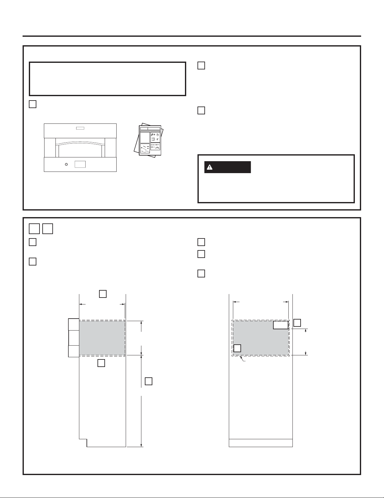
1 A
A
CUTOUT FOR 30” (76.2 CM) ELECTRIC INDOOR PIZZA OVEN
47” is the required minimum installation height. Oven
may be installed higher based on owner preference.
B
Back of standard depth cabinet may need to be
removed to install oven at correct depth. Drywall is
acceptable as back enclosure.
B
24” (60.9) min
cutout depth
18 3/8” (46.6) min
18 7/16” (46.8) max
C
A
47” (119.4) min
C
Platform must be able to support 200 lbs (91 kg).
D
Solid enclosure required on the top, bottom, left and
right sides and back of oven.
E
Junction box location (May also be located in
adjacent cabinet)
28 1/2” (72.4) min
28 5/8” (72.7) max
ELEC
D
Solid enclosure
required on the
top, bottom, left
and right sides,
and back of oven
E
4” (10.2) min
to bottom of
junction box
INSTALLATION
SIDE VIEW
INSTALLATION
FRONT VIEW
31-11062 3
Page 4
Installation Instructions
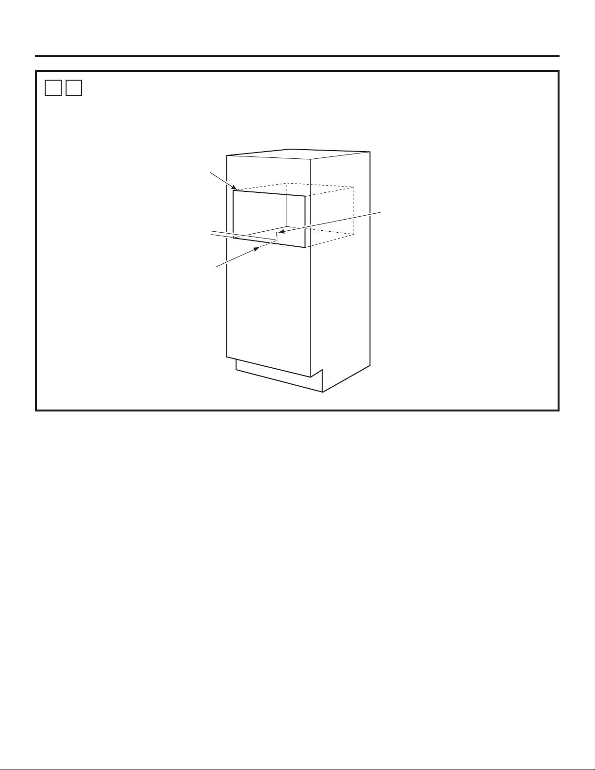
1 B
Use a drill with 1/8” drill bit to drill a pilot hole for the 1” drywall screw. Screw is installed 3” from cabinet front face
and centered horizontally. Attach the tether to the enclosure bottom using the provided 1” drywall screw. The free
end of the tether will be secured to the pizza oven case in step 3.
TETHER INSTALLATION (Required)
Pizza Oven Cutout
1” drywall screw
3” (76.2)
Tether
4 31-11062
Page 5
Installation Instructions
2
ELECTRICAL CONNECTIONS
ATTENTION INSTALLER
All electric wall ovens must be hard wired (direct
wired) into an approved junction box. A plug and
receptacle is NOT permitted on these products.
Do not shorten the flexible conduit. The conduit
strain relief clamp must be securely attached to
the junction box and the flexible conduit must
be securely attached to the clamp. If the flexible
conduit will not fit within the clamp, do not
install the oven until a clamp of the proper size is
obtained.
RECOMMENDED INSTALLATION OPTIONS
NOTE TO ELECTRICIAN: The 3 power leads supplied
with this appliance are UL recognized for connection
to heavier gauge household wiring. The insulation of
these 3 leads is rated at temperatures much higher
than the temperature rating of household wiring.
The current carrying capacity of the conductor is
governed by the wire gauge and the temperature
rating of the insulation around the wire.
WARNING
aluminum house wiring to copper leads can
result in an electrical hazard or fire. Use only
connectors designed for joining copper to
aluminum and follow the manufacturer’s
recommended procedure closely.
Improper connection of
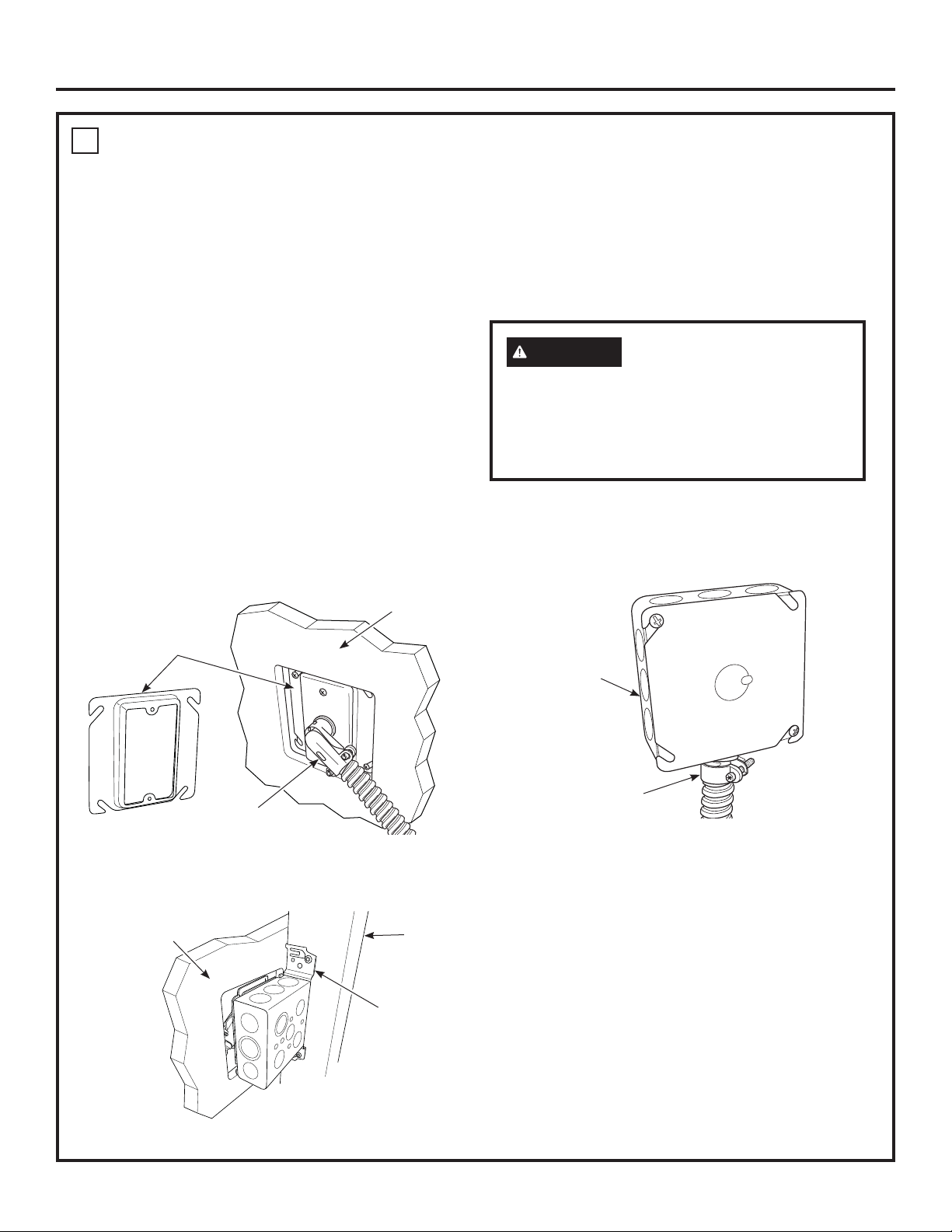
Option 1 - A junction box with a plaster ring and 90°
strain relief, mounted to a stud behind
the drywall.
Front of Drywall
Plaster Ring
90° Strain Relief
FRONT VIEW
Back of Drywall
Stud
Option 2 - Standard junction box with a straight
strain relief.
Junction Box
Straight Strain Relief
Mounted
Junction Box
BACK VIEW
31-11062 5
Page 6

Installation Instructions
2
ELECTRICAL CONNECTIONS (Cont)
1. Turn off the circuit breaker or remove fuses to the
oven branch circuit.
2. With the oven supported on a table or platform in
front of the cabinet opening, connect the flexible
conduit to the electrical junction box as shown
below. Position the conduit in such a manner that
it will lie in a natural loop, in the conduit pocket
behind the unit, when the oven is installed. You will
need to purchase an appropriate strain relief clamp
to complete the connection of the conduit to the
junction box.
Junction Box Location
Conduit
GROUND
WIRE
A
NEW CONSTRUCTION AND FOUR-
CONDUCTOR BRANCH CIRCUIT CONNECTION
• When installing in new construction, or
• When installing in a mobile home, or
• When installing in a recreational vehicle, or
• When local codes do not permit grounding through
neutral:
NOTE: If residence leads or ground are aluminum
conductors, see WARNING on page 5.
When connecting to a four-conductor branch circuit, if
local codes permit:
1. Free the neutral (white) lead from being restrained
to any other wires. If necessary, cut the neutral
(white) lead and then re-strip it to expose the
proper length of conductor.
2. Attach the appliance grounding lead (green or bare
copper) in accordance with local codes.
to assist in connecting
conduit, must support
200lbs (91kg).
GROUND
RED
WHITE
BLACK
Strain Relief Clamp
(not included) must be
used at Junction Box.Place oven on a support
Range
conduit
snaps
into box
Red
Junction Box Cover
Black
White
Branch
circuit
Ground
wires
Alternate
knockout
3. Connect the oven neutral (white) lead to the branch
circuit neutral (white or gray) in accordance with
local codes, using a wire nut.
4. Connect the oven red lead to the branch circuit red
lead and the oven black lead to the branch circuit
black lead in accordance with local codes, using
wire nuts.
5. Install proper strain relief clamp.
6. Install junction box cover.
6 31-11062
Page 7

Installation Instructions
2
ELECTRICAL CONNECTIONS (Cont)
B
THREE-CONDUCTOR BRANCH CIRCUIT
CONNECTION
NOTE: If residence leads are aluminum conductors,
see WARNING on page 5.
When connecting to a three-conductor branch circuit,
if local codes permit:
1. Connect the oven ground conductor along with the
neutral (white) lead to the branch circuit neutral
(white or gray in color), using a wire nut.
Range
conduit
snaps
into box
Red
Junction Box Cover
Black
Neutral wire
connection
Branch
circuit
Alternate
knockout
Tape or Crimp
Ground and
neutral wires (white)
2. Connect the oven red lead to the branch circuit red
lead and the oven black lead to the branch circuit
black lead in accordance with local codes, using
wire nuts.
3. Install proper strain relief clamp.
4. Install junction box cover.
3
INSTALLING THE OVEN IN THE
OPENING
1. Lift oven into cabinet cutout using the bottom as a
grip. Do not lift by the oven opening.
2. Carefully slide the oven back into the cutout until it
is about 2” from contacting cabinet face.
2” (5.1)
3. Attach the free end of the tether to the bottom
of the pizza oven case using the provided
5/8” Phillips case screw.
Bottom of
Pizza Oven
Tether
5/8” Phillips
Case Screw
4. Finish sliding the oven into the cabinet. The oven is
fully installed when the standoffs touch the cabinet
front face.
Standoff
Cabinet
Front Face
31-11062 7
Page 8

Installation Instructions
PRE-TEST CHECKLIST
Remove all protective film, if present.
Check to be sure that all wiring is secure and not
pinched.
Remove cooking deck shipping supports by:
1. Pulling down on the shipping support by the
handle.
2. Rotating the shipping support towards the
cooking deck.
3. Pull out from oven and discard.
OPERATION CHECKLIST
IMPORTANT
• Remove all items from the inside of the oven.
• Check that conduit is securely connected to the
junction box.
• Turn on the power to the oven. (Refer to your Owner’s
Manual.) Verify that all cooking functions operate
properly.
• Check that the circuit breaker is not tripped nor the
house fuse blown.
• See your Owner’s Manual for troubleshooting list.
Remove both shipping supports
Handle
2
11
Shipping Supports
NOTE TO ELECTRICIAN: The power leads supplied
with this appliance are UL recognized for connections
to larger gauge household wiring. The insulation of
these leads is rated at temperatures much higher
than the temperature rating of household wiring. The
current carrying capacity of a conductor is governed
by the wire gauge and also the temperature rating of
the insulation around the wire.
NOTE: ALUMINUM WIRING
A.
B. Splice copper wires to aluminum wiring using
NOTE: Wire used, location and enclosure of
WARNING
ALUMINUM HOUSE WIRING TO THE COPPER
LEADS CAN RESULT IN AN ELECTRICAL
HAZARD OR FIRE.
special connectors designed and UL approved
for joining copper to aluminum, and follow
the manufacturer’s recommended connector
procedure closely.
splices, etc., must conform to good wiring
practice and local codes.
IMPROPER CONNECTION OF
2
8 31-11062
Page 9

Instrucciones
Horno Eléctrico Interno para Pizza
de instalación
ZEP30
Ante cualquier duda, llame a GE Appliances al 800.GE.CARES (800.432.2737)
o visite nuestro sitio Web en: GEAppliances.com
ANTES DE EMPEZAR
Lea estas instrucciones cuidadosa y completamente.
• IMPORTANTE — Guarde estas instrucciones
y téngalas disponibles para el inspector local.
• IMPORTANTE — Observe todos los
códigos y ordenanzas vigentes.
• Nota al instalador – Cerciórese de dejar estas
instrucciones con el propietario.
• Nota al consumidor – Guarde estas instrucciones para
usarlas como referencia en el futuro.
• La instalación apropiada es responsabilidad del
instalador y la falla del producto por una instalación
incorrecta NO está cubierta por la garantía.
• Nota – Este aparato debe estar conectado a tierra
adecuadamente.
• ¡ATENCIÓN AL INSTALADOR!
Todos los hornos electrónicos de pared deben ser
cableados directamente en una caja de conexión
aprobada. Un “enchufe-receptáculo” NO ES permitido en
estos productos.
MATERIALES NECESARIOS
Opción 1
Abrazadera de alivio de presión
para conducto de 1/2”
Anillo de Yeso
(Opción 1)
Opción 2
(Profundidad Máx. de 1 ½)
Tuercas para alambres
Caja de conexión
PARTES INCLUIDAS
(la apariencia puede variar)
Correa
Cepillo
Paleta Metálica
Tornillo de 1” para
Panel de Yeso
Tornillo Phillips
de 5/8” para Caja
Paleta de Madera
HERRAMIENTAS NECESARIOS
Alicates pelacables
Destornillador
con punta plana
Destornillador de
estrella #2
Taladro y broca de 1/8”
31-11062 12-16 GEA
Page 10

Instrucciones de instalación
INSTRUCCIONES DE SEGURIDAD IMPORTANTES
PARA SU SEGURIDAD
• Cerciórese de que su horno sea instalado adecuadamente
por un instalador calificado o por un técnico de servicio.
• Cerciórese de que su horno esté firmemente instalado en
un gabinete que esté firmemente adherido a la estructura
de la casa. Nunca permita que nadie se suba, se siente,
se pare o se cuelgue de del horno.
• Cerciórese de que los gabinetes y los revestimientos de
la pared alrededor del horno puedan soportar
las temperaturas (hasta 200°F [93,3°C]) generadas
por el horno.
ADVERTENCIA
la línea de suministro del horno debe ser
desconectada mientras se hacen las conexiones.
No hacer esto podría resultar en lesiones graves e
incluso provocar la muerte.
La energía eléctrica hacia
REQUISITOS ELÉCTRICOS
Este aparato debe abastecerse con la frecuencia y el
voltaje adecuados, y conectarse a un circuito eléctrico
individual con conexión a tierra con protección de un fusible
o interruptor automático. Lea la etiqueta de características
técnicas en la parte inferior del panel frontal, a fin de
determinar las especificaciones del producto. Utilice el
cuadro a continuación para determinar la protección mínima
recomendada para el circuito eléctrico especializado.
Requerido Tamaño
Potencia KW 240V
9,7 KW–12,0 KW 8,4 KW–10,4 KW 50 Amp
Potencia KW 208V
del circuito
(Especializado)
REQUISITOS ELÉCTRICOS
La etiqueta de características técnicas está ubicada en la
parte inferior del panel frontal.
Ubicación de la placa de potencia
Recomendamos que el cableado y la conexión eléctrica
de su horno los realice un electricista calificado. Después
de la instalación, solicite al electricista que le indique cómo
desconectar la energía de la cocina.
Consulte con su compañía de servicios local para obtener
los códigos eléctricos que sean aplicables en su área.
No hacer el cableado de su horno de manera apropiada,
respetando los códigos vigentes, podría resultar en
condiciones peligrosas. Si no existen códigos locales, su
aparato debe usar un cableado y fusibles que cumplan con
los requisitos del Código Eléctrico Nacional, ANSI/NFPA No.
70–Última edición. Usted puede obtener una copia de este
código disponible en National Fire Protection Association
(Asociación Nacional de Protección contra Incendios).
A partir del 1ro. de enero de 1996, el Código Eléctrico
Nacional requiere que todas las construcciones nuevas, pero
no existentes, usen una conexión de 4 conductores hacia
cualquier horno eléctrico. Cuando instale un horno eléctrico en
una construcción nueva, casa móvil, vehículo de recreación
o un área donde los códigos locales prohíban la conexión a
tierra a través del conductor neutro, siga las instrucciones en
la Sección CONSTRUCCIONES NUEVAS Y CONEXIoNES
DE CIRCUITOS RAMALES DE 4 CONDUCTORES.
Usted debe usar un sistema eléctrico de fase única de
120/208 VAC o 120/240 VAC de 60 hercios. Si hace una
conexión a alambres de aluminio, debe usar conectores
adecuadamente instalados que estén aprobados para ser
utilizados con cableados de aluminio.
2 31-11062
Page 11

Instrucciones de instalación
LISTA DE CONTROL ANTES DE LA INSTALACIÓN
¡TODA LA INFORMACIÓN PARA LA INSTALACIÓN EN
LAS PÁGINAS SIGUIENTES ES PARA SER USADA EN
LA INSTALACIÓN DE HORNO ELÉCTRICO INTERNO
PARA PIZZA.
Retire los materiales de embalaje y extraiga el paquete de
instrucciones.
Be
Be
Bef
Bef
Bef
Bef
Bef
Bef
Be
Be
Be
Be
f
f
f
f
f
f
ore
ore
ore
ore
ore
ore
ore
ore
ore
ore
ore
ore
you
you
you
you
you
you
you
you
yo
yo
yo
yo
u
u
u
u
IM
IM
IM
IM
IM
IM
IM
IM
IM
IM
IM
IM
Installation
Electric Indoor Pizza Oven
be
be
be
be
be
be
be
be
be
be
be
be
P
P
P
P
P
P
P
P
P
P
P
P
g
g
g
g
g
g
g
g
g
g
g
g
O
O
O
O
O
O
O
O
O
O
O
O
i
i
i
i
i
i
i
i
i
i
i
i
RT
RT
RT
RT
RT
RT
RT
RT
RT
RT
RT
RT
n
n
n
n
n
n
n
n
n
n
n
n
-
-
-
-
-
-
-
-
-
-
-
-
Re
Re
Re
Re
R
R
R
R
R
R
R
R
ANT-
ANT-
ANT-
ANT-
AN
AN
ANT-
ANT-
ANT-
ANT-
AN
AN
e
e
e
e
e
e
e
e
ad
ad
ad
ad
ad
ad
ad
ad
ad
ad
ad
ad
IM
IM
IM
IM
IM
IM
IM
IM
IMPORT
IMPORT
IMPORT
IMPORT
T-
T-
T-
T-
PO
PO
PO
PO
PO
PO
PO
PO
th
th
th
th
th
th
th
th
th
th
th
th
Sa
Sa
Sa
Sa
Sa
Sa
Sa
Sa
Sa
Sa
Sa
Sa
es
es
es
es
es
es
es
es
es
es
es
es
RT
RT
RT
RT
RT
RT
RT
RT
ve
ve
ve
ve
ve
ve
ve
ve
ve
ve
ve
ve
e i
e i
e i
e i
e i
e i
e i
e i
e
e
e
e
AN
AN
AN
AN
AN
AN
ANT-
ANT-
AN
AN
AN
AN
th
th
thes
thes
thes
thes
thes
thes
thes
thes
th
th
i
i
i
i
ZEP30
n
n
n
n
n
n
n
n
n
n
n
n
Instructions
No
No
No
No
No
No
No
No
No
No
No
No
es
es
es
es
str
str
s
s
s
s
s
s
s
s
s
s
T-
T-
T-
T-
T-
T-
T-
T-
T-
T-
t
t
t
t
t
t
t
t
t
t
r
r
ructio
ructio
ructio
ructio
ru
ru
ru
ru
e
e
e in
e in
e in
e in
e in
e in
e in
e in
e in
e in
te
te
te
te
te
te
te
te
te
te
te
te
u
u
u
u
OB
OB
OB
OB
OB
OB
OB
OB
OB
OB
OB
OB
in
in
ct
ct
ct
ct
ct
ct
ct
ct
to
to
to
to
to
to
to
to
to
to
to
to
st
st
st
st
st
st
s
s
s
s
s
s
SER
SER
SER
SER
SER
SER
SER
SER
SER
SER
SER
SER
io
io
ions
ions
io
io
io
io
t
t
t
t
t
t
r
r
r
r
r
r
r
r
r
r
r
r
In
In
Inst
Inst
In
In
In
In
In
In
In
In
ns
ns
ns
ns
ns
ns
ns
ns
ns
ns
u
u
u
u
u
u
u
u
u
u
u
u
V
V
VE
VE
VE
VE
VE
VE
V
V
V
V
ct
ct
ct
ct
ct
ct
ct
ct
ct
ct
ct
ct
s
s
st
st
st
st
s
s
s
s
OW
OW
OW
OW
OW
OW
OW
OW
OW
OW
OW
OW
t
t
t
t
t
t
co
co
co
co
co
co
co
co
co
co
co
co
E
E
E
E
E
E
al
al
al
al
al
al
al
al
alle
alle
alle
alle
ions
ions
ions
ions
io
io
io
io
io
io
io
io
A
A
A
A
A
A
A
A
A
A
A
A
m
m
m
m
m
m
m
m
m
m
m
m
le
le
le
le
le
le
le
le
ns
ns
ns
ns
ns
ns
ns
ns
NE
NE
NE
NE
NE
NE
NE
NE
NE
NE
NE
NE
LL
LL
LL
LL
LL
LL
LL
LL
LL
LL
LL
LL
r
r
r
r
r
r
r
r
r
r
r
r
ple
ple
ple
ple
plete
plete
plete
plete
ple
ple
ple
ple
-
-
-
-
-
-
-
-
-
-
-
-
fo
fo
fo
fo
fo
fo
for
for
for
for
fo
fo
R-
R-
R-
R-
R-
R-
R-
R-
R-
R-
R-
R-
GO
GO
GO
GO
GO
GO
GO
GO
GO
GO
GO
GO
Be
Be
Be
Be
Be
Be
Be
Be
Be
Be
Be
Be
r
r
r
r
r
r
r
r
te
te
te
te
te
te
te
te
K
K
K
K
K
K
K
K
K
K
Keep
Keep
lo
lo
lo
lo
lo
lo
lo
lo
lo
lo
lo
lo
su
su
su
su
su
su
su
su
su
su
su
su
VE
VE
VE
VE
VE
VE
VE
VE
VE
VE
VE
VE
ly
ly
ly
ly
ly
ly
ly
ly
ly
ly
ly
ly
No
No
No
No
No
No
No
No
No
No
No
No
ee
ee
ee
ee
ee
ee
eep
eep
eep
eep
ca
ca
ca
ca
ca
ca
ca
ca
ca
ca
ca
ca
an
an
an
an
an
an
an
an
an
an
an
an
re
re
re
re
re
re
re
re
re
re
re
re
RN
RN
RN
RN
RN
RN
RN
RN
RN
RN
RN
RN
p
p
p
p
p
p
If you have questions, call GE Appliances at 800.GE.CARES (800.432.2737)
te
te
te
te
te
te
te
te
te
te
te-
te-
l
l
l
l
l
l
l
l
l
l
l
l
th
th
th
th
th
th
th
th
thes
thes
thes
thes
i
i
i
i
i
i
in
in
in
in
i
i
to
to
to
to
t
t
t
t
t
t
t
t
d
d
d
d
d
d
d
d
d
d
d
d
-
-
-
-
-
-
-
-
-
-
n
n
n
n
n
n
n
n
IN
IN
IN
IN
IN
IN
IN
IN
IN
IN
IN
IN
o
o
o
o
o
o
o
o
Th
Th
Th
Th
This
This
Th
Th
Th
Th
Th
Th
sp
sp
sp
sp
sp
sp
sp
sp
sp
sp
sp
sp
es
es
es
es
es
es
es
es
ca
ca
care
care
care
care
ca
ca
ca
ca
ca
ca
le
le
le
le
le
le
le
le
le
le
le
le
G
G
G
G
G
G
G
G
G
G
G
G
e i
e i
e i
e i
e
e
e in
e in
e in
e in
e i
e i
ec
ec
ec
ec
ec
ec
ec
ec
ec
ec
ec
ec
is
is
is
is
is
is
is
is
is
is
refu
refu
refully
refully
re
re
re
re
av
av
av
av
av
av
av
av
av
av
av
av
CODE
CODE
CODE
CODE
CODES
CODES
CODES
CODES
CO
CO
CO
CO
a
a
a
a
a
a
a
a
a
a
a
a
i
i
fu
fu
fu
fu
fu
fu
fu
fu
n
n
n
n
n
n
n
n
t
t
t
t
t
t
t
t
t
t
t
t
e
e
e
e
e
e
e
e
e
e
e
e
or visit our website at: GEAppliances.com.
or'
or'
or'
or'
or'
or'
or'
or'
or'
or'
or'
or'
ppliance
ppliance
ppliance
ppliance
pplian
pplian
pplian
pplian
pplian
pplian
pplian
pplian
stru
stru
stru
stru
st
st
st
st
st
st
st
st
DES
DES
DES
DES
lly
lly
lly
lly
lly
lly
lly
lly
lly
lly
th
th
th
th
th
th
th
th
th
th
th
th
ruct
ruct
ruct
ruct
ru
ru
ru
ru
s
s
s
s
s
s
s
s
s
s
s
s
.
.
.
.
.
.
.
.
.
.
.
.
es
es
es
es
es
es
es
es
es
es
es
es
S
S
S
S
us
us
us
us
us
us
us
us
us
us
us
us
ct
ct
ct
ct
ct
ct
ct
ct
AN
AN
AN
AN
AND
AND
AND
AND
AND
AND
AND
AND
e in
e in
e in
e in
e
e
e
e
e in
e in
e in
e in
io
io
io
io
io
io
io
io
ions
ions
ions
ions
e.
e.
e.
e.
e.
e.
e.
e.
e.
e.
e.
e.
ce
ce
ce
ce
ce
ce
ce
ce
in
in
in
in
ns
ns
ns
ns
ns
ns
ns
ns
D OR
D OR
D OR
D OR
st
st
s
s
s
s
s
s
stru
stru
stru
stru
mu
mu
mu
mu
mu
mu
mu
mu
mu
mu
mu
mu
t
t
t
t
t
t
OR
OR
OR
OR
OR
OR
OR
OR
f
f
f
f
f
f
f
f
for
for
for
for
ruct
ruct
ructio
ructio
ructio
ructio
ruct
ruct
or
or
or
or
or
or
or
or
s
s
s
s
s
s
s
s
st
st
st
st
ct
ct
ct
ct
DI
DI
DIAN
DIAN
DI
DI
DI
DI
DI
DI
DI
DI
t
t
t
t
t
t
t
t
fu
fu
fu
fu
fu
fu
fu
fu
fu
fu
fu
fu
ions
ions
io
io
io
io
io
io
be
be
be
be
be
be
be
be
be
be
be
be
A
A
A
A
A
A
A
A
A
A
tu
tu
tu
tu
tu
tu
tu
tu
tu
tu
tu
tu
ns
ns
ns
ns
ns
ns
ns
ns
ns
ns
NC
NC
N
N
N
N
NCE
NCE
NCE
NCE
p
p
p
p
p
p
p
p
p
p
p
p
re
re
re
re
re
re
re re
re re
re re
re re
re
re
CE
CE
C
C
C
C
rop
rop
rop
rop
rop
rop
rop
rop
rop
rop
rop
rop
wi
wi
wi
wi
wi
wi
wi
wi
wi
wi
wi
wi
E
E
E
E
E
E
re
re
re
re
re
re
re
re
S
S
S
S
S.
S.
S.
S.
S.
S.
S.
S.
t
t
t
t
t
t
t
t
t
t
t
t
.
.
.
.
h
h
h
h
h
h
h
h
h
h
h
h
e
e
e
e
e
e
e
e
e
e
e
e
fe
fe
fe
fe
fe
fe
ference.
ference.
ference.
ference.
ference.
ference.
BEFORE YOU BEGIN
MATERIALS NEEDED
r
r
r
r
r
r
r
r
r
r
r
r
th
th
th
th
the
the
th
th
th
th
th
th
renc
renc
renc
renc
rence.
rence.
ly
ly
ly
ly
ly
ly
ly
ly
ly
ly
ly
ly
e co
e co
e co
e co
e co
e co
e cons
e cons
e cons
e cons
groun
groun
groun
groun
grounded
grounded
grounded
grounded
groun
groun
groun
groun
co
co
e.
e.
e.
e.
FOR
FOR
FOR
FOR
ns
ns
ns
ns
ns
ns
ns
ns
u
u
u
u
u
u
u
u
u
u
u
u
ded
ded
ded
ded
ded
ded
ded
ded
Read these instructions carefully and completely.
YO
YO
YO
YO
mer
mer
mer
mer
mer.
mer.
mer.
mer.
mer.
mer.
mer.
mer.
UR
UR
UR
UR
(if
(if
(if
(if
(if
(if
(if
(if
(if
(if
(if
(if
.
.
.
.
a
a
a
a
a
a
a
a
a
a
a
a
SAFE
SAFE
SAFE
SAFE
pp
pp
pp
pp
pp
pp
ppli
ppli
ppli
ppli
ppli
ppli
lic
lic
lic
lic
lic
lic
c
c
c
c
c
c
TY
TY
TY
TY
ab
ab
ab
ab
able
able
able
able
able
able
able
able
Bef
Bef
Bef
Bef
le
le
le
le
or
or
or
or
•
IMPORTANT — Save these instructions
).
).
).
).
).
).
).
).
).
).
).
).
e
e
e
e
yo
yo
yo
yo
u
u
u
u
in
in
in
in
for local inspector’s use.
begi
begi
begi
begi
stru
stru
stru
stru
n
n
n
n
ct
ct
ct
ct
-
-
-
-
Read
Read
Read
Read
i
i
i
i
o
o
o
o
ns
ns
ns
ns
ca
ca
ca
ca
co
co
co
co
re
re
re
re
th
th
th
th
fu
fu
fu
fu
mple
mple
mple
mple
es
es
es
es
Option 2
lly
lly
lly
lly
•
IMPORTANT — Observe all governing
e
e
e
e
.
.
.
.
te
te
te
te
IM
IM
IM
IM
Option 1
ly
ly
ly
ly
PO
PO
PO
PO
an
an
an
an
codes and ordinances.
R
R
R
R
d
d
d
d
T
T
T
T
A
A
A
A
E
E
E
E
N
N
N
N
LE
LE
LE
LE
in
in
in
in
Strain Relief Clamp
T-
T-
T-
T-
CTR
CTR
CTR
CTR
st
st
st
st
Sa
Sa
Sa
Sa
ruct
ruct
ruct
ruct
• Note to Installer – Be sure to leave these
Junction Box
ve
ve
ve
ve
IC
IC
IC
IC
for 1/2” conduit
ions
ions
ions
ions
AL
AL
AL
AL
th
th
th
th
IMPO
IMPO
IMPO
IMPO
es
es
es
es
(1 1/2 Depth Max.)
RE
RE
RE
RE
instructions with the consumer.
fo
fo
fo
fo
e
e
e
e
QUIR
QUIR
QUIR
QUIR
r lo
r lo
r lo
r lo
RT
RT
RT
RT
Be
Be
Be
Be
ca
ca
ca
ca
ANT-
ANT-
ANT-
ANT-
E
E
E
E
M
M
M
M
f
f
f
f
l
l
l
l
ore
ore
ore
ore
GO
GO
GO
GO
in
in
in
in
E
E
E
E
• Note to Consumer – Keep these instructions for
N
N
N
N
sp
sp
sp
sp
O
O
O
O
VE
VE
VE
VE
yo
yo
yo
yo
TS
TS
TS
TS
e
e
e
e
B
B
B
B
c
RN
c
RN
c
RN
c
RN
SER
SER
SER
SER
u
u
u
u
t
t
t
t
in
in
in
in
or'
or'
or'
or'
be
be
be
be
future reference.
I
I
I
I
s
s
s
s
N
N
N
N
V
V
V
V
t
t
t
t
s
s
s
s
No
No
No
No
gin-
gin-
gin-
gin-
ru
ru
ru
ru
G
G
G
G
E
E
E
E
us
us
us
us
c
c
c
c
AL
AL
AL
AL
C
C
C
C
te
te
te
te
t
t
t
t
e
e
e
e
O
O
O
O
Re
Re
Re
Re
ions
ions
ions
ions
.
.
.
.
L
L
L
L
t
t
t
t
DES
DES
DES
DES
o
o
o
o
ad
ad
ad
ad
ca
ca
ca
ca
In
In
In
In
• Proper installation is the responsibility of the
co
co
co
co
r
r
r
r
th
th
th
th
st
st
st
st
e
e
e
e
AND
AND
AND
AND
th
th
th
th
fu
fu
fu
fu
mple
mple
mple
mple
al
al
al
al
es
es
es
es
es
es
es
es
lly
lly
lly
lly
le
le
le
le
e
e
e
e
e in
e in
e in
e in
r
r
r
r
OR
OR
OR
OR
.
.
.
.
installer and product failure due to improper
-
-
-
-
te
te
te
te
IM
IM
IM
IM
Be
Be
Be
Be
s
s
s
s
DIAN
DIAN
DIAN
DIAN
ly
ly
ly
ly
t
t
t
t
PO
PO
PO
PO
ru
ru
ru
ru
an
an
an
an
su
su
su
su
OW
OW
OW
OW
ct
ct
ct
ct
re
re
re
re
RT
RT
RT
RT
d
d
d
d
installation is NOT covered under warranty.
CE
CE
CE
CE
io
io
io
io
NE
NE
NE
NE
to
to
to
to
AN
AN
AN
AN
n
n
n
n
S.
S.
S.
S.
R-
R-
R-
R-
s
s
s
s
in
in
in
in
le
le
le
le
T-
T-
T-
T-
wi
wi
wi
wi
K
K
K
K
st
st
st
st
av
av
av
av
S
S
S
S
f
f
f
f
e
e
e
e
th
th
th
th
ru
ru
ru
ru
or
or
or
or
e
e
e
e
a
a
a
a
ep
ep
ep
ep
v
v
v
v
ct
ct
ct
ct
• Note – This appliance must be properly grounded.
th
th
th
th
fu
fu
fu
fu
e
e
e
e
ions
ions
ions
ions
th
th
th
th
e
e
e
e
th
th
th
th
ture
ture
ture
ture
e
e
e
e
con
con
con
con
IM
IM
IM
IM
e
e
e
e
s
s
s
s
s
s
s
s
e
e
e
e
fo
fo
fo
fo
Wire Nuts
e
e
e
e
re
re
re
re
PO
PO
PO
PO
No
No
No
No
in
in
in
in
s
s
s
s
r lo
r lo
r lo
r lo
u
u
u
u
fe
fe
fe
fe
st
st
st
st
RT
RT
RT
RT
mer.
mer.
mer.
mer.
te
te
te
te
ren
ren
ren
ren
ru
ru
ru
ru
ca
ca
ca
ca
AN
AN
AN
AN
-
-
-
-
ct
ct
ct
ct
Th
Th
Th
Th
l
l
l
l
c
c
c
c
GO
GO
GO
GO
in
in
in
in
T-
T-
T-
T-
i
i
i
i
e.
e.
e.
e.
o
o
o
o
•
ATTENTION INSTALLER
i
i
i
i
sp
sp
sp
sp
s
s
s
s
ns
ns
ns
ns
Plaster Ring
OB
OB
OB
OB
VE
VE
VE
VE
a
a
a
a
prop
prop
prop
prop
e
e
e
e
pplian
pplian
pplian
pplian
c
c
c
c
RN
RN
RN
RN
SER
SER
SER
SER
t
t
t
t
or's
or's
or's
or's
erly
erly
erly
erly
IN
IN
IN
IN
(Option 1)
V
V
V
V
No
No
No
No
G
G
G
G
E
E
E
E
ce
ce
ce
ce
us
us
us
us
All electric wall ovens must be hard wired (direct
ground
ground
ground
ground
COD
COD
COD
COD
A
A
A
A
te
te
te
te
e.
e.
e.
e.
mu
mu
mu
mu
LL
LL
LL
LL
Be
Be
Be
Be
to
to
to
to
st
st
st
st
f
f
f
f
E
E
E
E
ore
ore
ore
ore
In
In
In
In
S
S
S
S
wired) into an approved junction box. A plug and
be
be
be
be
ed
ed
ed
ed
st
st
st
st
AN
AN
AN
AN
th
th
th
th
yo
yo
yo
yo
al
al
al
al
es
es
es
es
(
(
(
(
D
D
D
D
if
if
if
if
le
le
le
le
u
u
u
u
e in
e in
e in
e in
i
i
i
i
a
a
a
a
r-
r-
r-
r-
OR
OR
OR
OR
n
n
n
n
b
b
b
b
pplica
pplica
pplica
pplica
receptacle is NOT permitted on these products.
st
st
st
st
Be
Be
Be
Be
e
e
e
e
st
st
st
st
D
D
D
D
gi
gi
gi
gi
ruct
ruct
ruct
ruct
I
I
I
I
ru
ru
ru
ru
su
su
su
su
ANCE
ANCE
ANCE
ANCE
n-
n-
n-
n-
OW
OW
OW
OW
ct
ct
ct
ct
ble
ble
ble
ble
r
r
r
r
R
R
R
R
ions
ions
ions
ions
e
e
e
e
e
e
e
e
ions
ions
ions
ions
NE
NE
NE
NE
ad
ad
ad
ad
to
to
to
to
ca
ca
ca
ca
).
).
).
).
S.
S.
S.
S.
R-
R-
R-
R-
comple
comple
comple
comple
re
re
re
re
le
le
le
le
TOOLS NEEDED
the
the
the
the
wi
wi
wi
wi
K
K
K
K
fu
fu
fu
fu
av
av
av
av
f
f
f
f
e
e
e
e
th
th
th
th
s
s
s
s
lly
lly
lly
lly
or
or
or
or
e
e
e
e
ep
ep
ep
ep
e
e
e
e
th
th
th
th
.
.
.
.
fu
fu
fu
fu
te
te
te
te
th
th
th
th
IM
IM
IM
IM
e co
e co
e co
e co
tu
tu
tu
tu
ly
ly
ly
ly
es
es
es
es
P
P
P
P
r
r
r
r
an
an
an
an
e
e
e
e
O
O
O
O
e in
e in
e in
e in
ns
ns
ns
ns
re
re
re
re
RT
RT
RT
RT
No
No
No
No
d
d
d
d
u
u
u
u
fe
fe
fe
fe
stru
stru
stru
stru
A
A
A
A
mer.
mer.
mer.
mer.
te
te
te
te
ren
ren
ren
ren
NT-
NT-
NT-
NT-
PARTS INCLUDED
in
in
in
in
-
-
-
-
ct
ct
ct
ct
Thi
Thi
Thi
Thi
st
st
st
st
c
c
c
c
i
i
i
i
Sa
Sa
Sa
Sa
e.
e.
e.
e.
o
o
o
o
ru
ru
ru
ru
s
s
s
s
ns
ns
ns
ns
ve
ve
ve
ve
a
a
a
a
pr
pr
pr
pr
ct
ct
ct
ct
pplian
pplian
pplian
pplian
ions
ions
ions
ions
operl
operl
operl
operl
t
t
t
t
(Appearance will vary)
h
h
h
h
IM
IM
IM
IM
e
e
e
e
s
s
s
s
for
for
for
for
e
e
e
e
PO
PO
PO
PO
y
y
y
y
ce
ce
ce
ce
ground
ground
ground
ground
lo
lo
lo
lo
RT
RT
RT
RT
Be
Be
Be
Be
mu
mu
mu
mu
ca
ca
ca
ca
ANT-
ANT-
ANT-
ANT-
f
f
f
f
ore
ore
ore
ore
st
st
st
st
l
l
l
l
GO
GO
GO
GO
in
in
in
in
Phillips #2
be
be
be
be
ed
ed
ed
ed
sp
sp
sp
sp
yo
yo
yo
yo
OB
OB
OB
OB
VE
VE
VE
VE
Wire Strippers
e
e
e
e
(if
(if
(if
(if
u
u
u
u
RN
RN
RN
RN
c
c
c
c
in
in
in
in
SERV
SERV
SERV
SERV
t
t
t
t
be
be
be
be
a
a
a
a
or'
or'
or'
or'
st
st
st
st
Screwdriver
pplica
pplica
pplica
pplica
IN
IN
IN
IN
gi
gi
gi
gi
ruct
ruct
ruct
ruct
s
s
s
s
No
No
No
No
G
G
G
G
E A
E A
E A
E A
n-
n-
n-
n-
us
us
us
us
CODES
CODES
CODES
CODES
te
te
te
te
Re
Re
Re
Re
i
i
i
i
e
e
e
e
o
o
o
o
LL
LL
LL
LL
ble
ble
ble
ble
.
.
.
.
ns
ns
ns
ns
to
to
to
to
ad
ad
ad
ad
ca
ca
ca
ca
).
).
).
).
In
In
In
In
comple
comple
comple
comple
r
r
r
r
t
t
t
t
e
e
e
e
hes
hes
hes
hes
s
s
s
s
AND OR
AND OR
AND OR
AND OR
th
th
th
th
fu
fu
fu
fu
t
t
t
t
alle
alle
alle
alle
lly
lly
lly
lly
e
e
e
e
e
e
e
e
s
s
s
s
e
e
e
e
.
.
.
.
r
r
r
r
tely
tely
tely
tely
-
-
-
-
in
in
in
in
IM
IM
IM
IM
Be
Be
Be
Be
Tether
struct
struct
struct
struct
DIAN
DIAN
DIAN
DIAN
1” Drywall Screw
PO
PO
PO
PO
an
an
an
an
su
su
su
su
OW
OW
OW
OW
RT
RT
RT
RT
d
d
d
d
r
r
r
r
e
e
e
e
CE
CE
CE
CE
i
i
i
i
NER-
NER-
NER-
NER-
AN
AN
AN
AN
o
o
o
o
to
to
to
to
ns
ns
ns
ns
S.
S.
S.
S.
in
in
in
in
T-
T-
T-
T-
le
le
le
le
st
st
st
st
wi
wi
wi
wi
K
K
K
K
av
av
av
av
Sa
Sa
Sa
Sa
Flathead
r
r
r
r
f
f
f
f
e
e
e
e
th
th
th
th
u
u
u
u
or
or
or
or
e
e
e
e
ep
ep
ep
ep
ve
ve
ve
ve
ct
ct
ct
ct
th
th
th
th
fu
fu
fu
fu
io
io
io
io
th
th
th
th
th
th
th
th
e
e
e
e
ns
ns
ns
ns
tu
tu
tu
tu
Screwdriver
I
I
I
I
es
es
es
es
es
es
es
es
M
M
M
M
co
co
co
co
r
r
r
r
fo
fo
fo
fo
e
e
e
e
e
e
e
e
PO
PO
PO
PO
e i
e i
e i
e i
ns
ns
ns
ns
re
re
re
re
r lo
r lo
r lo
r lo
No
No
No
No
n
n
n
n
u
u
u
u
RT
RT
RT
RT
fe
fe
fe
fe
st
st
st
st
mer
mer
mer
mer
te
te
te
te
ca
ca
ca
ca
ren
ren
ren
ren
AN
AN
AN
AN
r
r
r
r
Brush
u
u
u
u
-
-
-
l
l
l
l
ct
ct
ct
ct
GO
GO
GO
GO
Th
Th
Th
Th
in
in
in
in
.
.
.
.
T-
T-
T-
T-
c
c
c
c
5/8” Phillips
i
i
i
i
e.
e.
e.
e.
s
s
s
s
o
o
o
o
i
i
i
i
p
p
p
p
OB
OB
OB
OB
s
s
s
s
VE
VE
VE
VE
ns
ns
ns
ns
Drill and 1/8” drill bit
a
a
a
a
p
p
p
p
ect
ect
ect
ect
rop
rop
rop
rop
RN
RN
RN
RN
pplian
pplian
pplian
pplian
SERVE
SERVE
SERVE
SERVE
Case Screw
or's
or's
or's
or's
IN
IN
IN
IN
e
e
e
e
No
No
No
No
rly
rly
rly
rly
G
G
G
G
us
us
us
us
ce
ce
ce
ce
ground
ground
ground
ground
A
A
A
A
CO
CO
CO
CO
te
te
te
te
e.
e.
e.
e.
LL
LL
LL
LL
mu
mu
mu
mu
to
to
to
to
DES
DES
DES
DES
In
In
In
In
s
s
s
s
t
t
t
t
stal
stal
stal
stal
AN
AN
AN
AN
the
the
the
the
be
be
be
be
ed
ed
ed
ed
D OR
D OR
D OR
D OR
le
le
le
le
(i
(i
(i
(i
s
s
s
s
e in
e in
e in
e in
f
f
f
f
r
r
r
r
-
-
-
-
a
a
a
a
ppli
ppli
ppli
ppli
Be
Be
Be
Be
st
st
st
st
DI
DI
DI
DI
ruct
ruct
ruct
ruct
s
s
s
s
ANCE
ANCE
ANCE
ANCE
OW
OW
OW
OW
ca
ca
ca
ca
u
u
u
u
r
r
r
r
ble
ble
ble
ble
e
e
e
e
ions
ions
ions
ions
NE
NE
NE
NE
to
to
to
to
S.
S.
S.
S.
).
).
).
).
R
R
R
R
le
le
le
le
- Keep
- Keep
- Keep
- Keep
wi
wi
wi
wi
av
av
av
av
f
f
f
f
th
th
th
th
or
or
or
or
e
e
e
e
th
th
th
th
fu
fu
fu
fu
t
t
t
t
e co
e co
e co
e co
hes
hes
hes
hes
tu
tu
tu
tu
r
r
r
r
e
e
e
e
e in
e in
e in
e in
n
n
n
n
re
re
re
re
No
No
No
No
s
s
s
s
u
u
u
u
fe
fe
fe
fe
st
st
st
st
mer
mer
mer
mer
te
te
te
te
r
r
r
r
ruc
ruc
ruc
ruc
e
e
e
e
-
-
-
-
Wooden Peel
nc
nc
nc
nc
Th
Th
Th
Th
.
.
.
.
t
t
t
t
io
io
io
io
e.
e.
e.
e.
is
is
is
is
Metal Peel
n
n
n
n
a
a
a
a
p
p
p
p
s
s
s
s
r
r
r
r
p
p
p
p
op
op
op
op
p
p
p
p
lian
lian
lian
lian
e
e
e
e
r
r
r
r
ly
ly
ly
ly
ce
ce
ce
ce
ground
ground
ground
ground
mu
mu
mu
mu
st
st
st
st
31-11062 12-16 GEA
be
be
be
be
ed
ed
ed
ed
(
(
(
(
if
if
if
if
a
a
a
a
pplica
pplica
pplica
pplica
b
b
b
b
le
le
le
le
).
).
).
).
Literature Pack
1 A
A
ESPACIO LIBRE DEL HORNO ELÉCTRICO INTERNO PARA PIZZA DE 30”
47” es la altura de instalación mínima requerida. El
horno podrá ser instalado más arriba, dependiendo de la
preferencia del propietario.
B
Es posible que sea necesario retirar la parte trasera de un
gabinete de profundidad estándar para instalar el horno
en la profundidad correcta. Un panel de yeso es aceptable
como cerramiento trasero.
Extraiga las instrucciones de instalación del paquete y
léalas cuidadosamente antes de empezar la instalación.
Cerciórese de guardar bien todas las instrucciones,
Manual del propietario, Instalación, etc. para referencia en
el futuro.
Coloque el horno sobre la mesa o plataforma al nivel de
la abertura del gabinete. La plataforma debe soportar 200
lbs. (91 Kg).Estos hornos no están aprobados para las
instalaciones apilables.
Estos hornos no están aprobados para las instalaciones
apilables.
PRECAUCIÓN
La instalación del horno por
debajo de la altura mínima de 47 pulgadas crea
riesgos de incendio para los niños. No instale el
mismo debajo de la altura mínima.
C
La plataforma deberá poder soportar 200 libras (91 kg).
D
Se requiere un cerramiento sólido en las partes superior,
inferior, izquierda, derecha y trasera del horno.
E
Ubicación de la caja de empalmes (también podrá estar
ubicada en un gabinete adyacente)
B
Profundidad de
espacio libre mín.
de 24” (60.9)
Mín. de 18 3/8” (46.6)
Máx. de 18 7/16” (46.8)
C
Mín. de 47” (119.4)
VISTA LATERAL DE
LA INSTALACIÓN
Mín. de 28 1/2” (72.4)
Máx. de 28 5/8” (72.7)
ELEC
E
Mín. de 4” (10.2) hasta
la parte inferior de la
D
caja de empalmes
Se requiere un
cerramiento sólido
en las partes
A
superior, inferior,
izquierda, derecha
y trasera del horno.
VISTA FRONTAL DE
LA INSTALACIÓN
31-11062 3
Page 12

Instrucciones de instalación
1 B
Use un taladro con una broca de 1/8” para hacer un agujero piloto para el tornillo de la pared de yeso de 1”. El tornillo debe
ser instalado a 3” de la cara frontal del gabinete y estar centrado horizontalmente. Adhiera la correa a la parte inferior del
cerramiento utilizando el tornillo para pared de yeso de 1” provisto. El extremo libre de la correa será asegurado al gabinete del
horno para pizza en el paso 3.
INSTALACIÓN DE LA CORREA (Requerida)
Espacio Libre del
Horno para Pizza
Tornillo de 1” para
pared de yeso
3” (76.2)
Correa
4 31-11062
Page 13

Instrucciones de instalación
2
CONEXIONES ELÉCTRICAS
ATENCIÓN AL INSTALADOR
Todos los hornos eléctricos de pared deben ser
cableados directamente en una caja de conexión.
Un “enchufe-receptáculo” NO ES permitido en estos
productos.
NO acorte el conducto flexible. La abrazadera para
controlar la presión debe estar firmemente adherida a
la caja de conexión y el conductor flexible debe estar
firmemente adherido a la abrazadera. Si el conducto
flexible no se ajusta al interior de la abrazadera, no instale
el horno hasta que obtenga el tamaño apropiado.
OPCIONES DE INSTALACIÓN RECOMENDADAS
Opción 1 - Una caja de empalmes con un anillo de yeso
y un amortiguador de refuerzo a 90°, sobre un montante
detrás de la pared de yeso.
Frente de la
Pared de Yeso
Nota al electricista: Los 3 alambres eléctricos
proporcionados con este aparato son reconocidos por
la UL para conexiones a cableado residencial de mayor
calibre. El aislante de estos 3 alambres supera las
especificaciones de temperatura indicadas para cableado
residencial. La capacidad actual de conducción del cable
depende del calibre del cableado y de la clasificación de
la temperatura del aislamiento alrededor del alambre.
Opción 2 - Caja de empalmes estándar con un
amortiguador de refuerzo recto.
ADVERTENCIA
Una conexión inapropiada
del cableado de aluminio residencial
con cobre, podría resultar en un peligro
eléctrico o hasta en incendio. Use solamente
conectores diseñados para unir cobre con
aluminio y siga las recomendaciones del
fabricante con mucho cuidado.
Anillo de Yeso
Parte Trasera de
la Pared de Yeso
Amortiguador de
Refuerzo a 90°
VISTA FRONTAL
Caja de
Empalmes
Amortiguador de
Refuerzo Recto
Montante
Caja de
Empalmes
Montada
VISTA TRASERA
31-11062 5
Page 14

Instrucciones de instalación
2
CONEXIONES ELÉCTRICAS (Cont)
1. Desconecte el interruptor del circuito o retire los fusibles
que alimentan el circuito ramal del horno.
2. Con el horno enfrente de la abertura del gabinete, sobre
una mesa o plataforma conecte el conducto flexible a la
caja de conexión como se muestra en la figura. Coloque
el conducto de manera que quede apoyado sobre la
parte superior del horno en forma de bucle natural
cuando se instale el horno. Usted necesitará comprar
una abrazadera liberadora de presión para completar la
conexión del conducto hacia la caja de conexión.
Ubicación de la caja de conexión
ALAMBRES DE
CONEXIÓN A
Conducto
TIERRA
ROJO
BLANCO
NEGRO
TIERRA
A
CONEXIÓN PARA NUEVA CONSTRUCCIÓN Y DE
CIRCUITO RAMAL DE CUATRO CONDUCTORES
• Cuando se instale en una construcción nueva, o
• Cuando se instale en una casa móvil, o
• Al instalar en un vehículo de recreacíon, o
• Cuando los códigos locales no permitan hacer conexión
a tierra a través de un cable neutro:
NOTA: Si los cables del hogar poseen conductores de
aluminio, ver la ADVERTENCIA en la página 5.
Cuando conecte un circuito derivado de cuatro
conductores, si lo permiten los códigos locales:
1. Conecte el conductor de conexión a tierra junto con el
cable neutro (blanco) al neutro del circuito de empalmes
(de color blanco o gris), usando una tuerca para cables.
2. Conecte el cable a tierra del artefacto (verde o cobre) de
acuerdo con los códigos locales.
Negro
El tubo de la
estufa se ajusta
en la caja
Rojo
Circuito ramificado
Cables a
tierra
Agujero ciego
alternativo
Blanco
Coloque el horno en el
soporte para ayudar en la
conexión del conductor, debe
soportar 200 libras (91kg).
Abrazadera liberadora
de presión (no incluida)
debe usarse en la caja
de conexión
Tapa de la caja de conexiones
3. Conecte el cable neutral (blanco) del horno con el neutral
de circuito derivado (blanco o gris) de acuerdo con
códigos locales, utilizando un tapón de alambre.
4. Conecte el cable rojo del horno al cable rojo del circuito
derivado y el cable negro del horno al cable negro del
circuito derivado de acuerdo con los códigos locales,
utilizando tapones de alambre.
5. Instale una abrazadera adecuada de alivio de tensión.
6. Instale la tapa de la caja de conexiones.
6 31-11062
Page 15

Instrucciones de instalación
2
CONEXIONES ELÉCTRICAS (Cont)
B
CONEXIÓN DE CIRCUITO RAMAL DE TRES
CONDUCTORES
NOTA: Si los cables domésticos son conductores de
aluminio, ver la ADVERTENCIA en la página 5.
Cuando conecte un circuito derivado de tres
conductores, si lo permiten los códigos locales:
1. Evite que el conductor neutro (blanco) quede
enredado con cualquier otro cable. De ser
necesario, corte el conductor neutro (blanco) y
luego vuelva a pelar el mismo, a fin de exponer la
longitud adecuada del conductor.
Negro
El tubo de la
estufa se ajusta
en la caja
Rojo
Cable neutral
conexión
Tapa de la caja de conexiones
Circuito ramificado
Agujero ciego
alternativo
Encinte o Prense
Cables a tierra
y neutrales (blanco)
2. Conecte el cable rojo del horno al cable rojo del
circuito derivado y el cable negro del horno al
cable negro del circuito derivado de acuerdo con
los códigos locales, utilizando tapones de alambre.
3. Instale una abrazadera adecuada de alivio de tensión.
4. Instale la tapa de la caja de conexiones.
3
INSTALACIÓN DEL HORNO
EN LA ABERTURA
1. Eleve el horno hasta el espacio libre para el gabinete
usando la parte inferior como agarre. No lo levante
desde la abertura del horno.
2. De forma cuidadosa, vuelva a deslizar el horno por el
espacio libre hasta que quede a aproximadamente 2”
desde la cara de contacto del gabinete.
2” (5.1)
3. Adhiera el extremo libre de la correa a la parte inferior
del gabinete del horno para pizza, usando el tornillo para
caja de 3/8” provisto.
Parte Inferior del
Horno para Pizza
Correa
Tornillo Phillips de
5/8” para Caja
4. Termine de deslizar el horno dentro del gabinete. El
horno estará completamente instalado cuando los
separadores toquen la cara frontal del gabinete.
Separador
Cara Frontal
del Gabinete
31-11062 7
Page 16

Instrucciones de instalación
LISTA DE CONTROL ANTES DE LA PRUEBA
De estar presente, retire toda la película protectora.
Revise para asegurarse de que todos los alambres estén
bien conectados y no aplastados.
Retire los soportes de embalaje de la superficie de cocción:
1. Bajando el soporte de embalaje desde la manija.
2. Girando el soporte de embalaje hacia la superficie
de cocción.
3. Retire el mismo del horno y descártelo.
Manija
Soportes de Embalaje
Retire ambos soportes de embalaje
11
LISTA DE CONTROL PARA LA OPERACIÓN
IMPORTANTE
2
2
• Retire cualquier artículo del interior del horno.
• Cerciórese de que el conducto está conectado firmemente a
la caja de conexión eléctrica.
• Conecte la energía hacia el horno. (Consulte su Manual del
propietario.) Verifique que todas las funciones de cocción
operen correctamente.
• Cerciórese de que el interruptor de circuito no se haya
disparado o de que los fusibles de la casa no estén
quemados.
• Consulte el manual del propietario para una lista de
problemas eventuales.
NOTA al electricista: Los alambres eléctricos
proporcionados con este aparato son reconocidos por la
UL para conexiones cableado residencial de mayor calibre.
El aislante de estos alambres supera las especificaciones
indicadas para cableado residencial. La capacidad actual
de conducción del cable depende de la clasificación de la
temperatura del aislamiento alrededor del alambre.
NOTA: Cableado de aluminio
A.
B. Conecte los alambres de cobre a los alambres de
NOTA: El alambrado que se use, la ubicación y el
WARNING
CABLEADO DEL ALUMINIO RESIDENCIAL CON EL
COBRE, PODRÍA RESULTAR EN PROBLEMAS SERIOS
O EN INCENDIO.
aluminio usando conectores especiales diseñados y
aprobados por UL para unir cobre y aluminio y siga
cuidadosamente el procedimiento para hacer las
conexiones recomendadas por el fabricante.
tipo de conexión, etc., deben cumplir con las buenas
prácticas de alambrado y los códigos locales.
UNA CONEXIÓN INAPROPIADA DEL
8 31-11062
 Loading...