

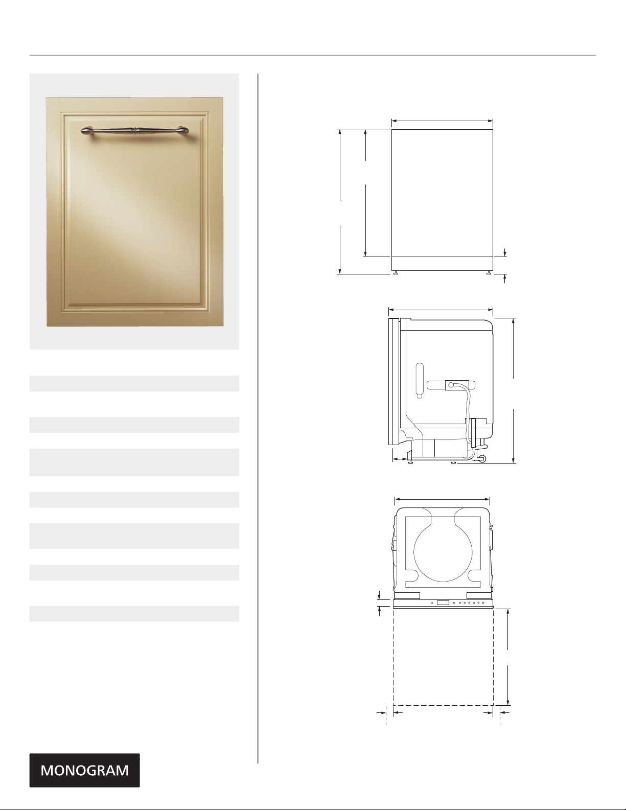
OVERALL DIMENSIONS
ZDT870SIFII & ZDT800SIFII
ZDT975SIJIIMONOGRAM 24" FULLY INTEGRATED DISHWASHER
23 3/4" (60.3)
SPECIFICATIONS
Overall Width 23 3/4" (60.3 cm)
Overall Height
Overall Depth 24" (61 cm)
Door Clearance 25 1/2" (64.8 cm)
Overall Dishwasher
Capacity
Minimum Cabinet Width 24" (61 cm)
Minimum Cabinet Depth 24" (61 cm)
Cutout Width 24" (61 cm)
Cutout Height
Electrical Requirements 9.0 A
Hose Length No more than 12' (3.7 m)
Voltz/Hertz/Amps
Shipping Weight 119 lb (54 kg)
33 3/8" (84.8 cm) Min
34 5/8" (88.0 cm) Max
16 Place Settings
33 1/2" (85.1 cm) Min
34 3/4" (88.3 cm) Max
115 V, 60 Hz,
15 or 20 amp circuit
29 13/16" min
30 1/4" max
33 3/8" min
34 5/8" max
(84.8 - 88.0)
1 7/16" (3.6)
(75.7 - 76.8)
3 1/2"
(8.9)
FRONT VIEW
24" (61.0)
SIDE VIEW
23 3/4" (60.3)
TOP VIEW
3 3/8" min
4 5/8" max
(8.6 - 11.8)
Toe kick
height
33 3/8" min
34 5/8" max
(84.8 - 88.0)
Height at rear
OPEN DISHWASHER DOOR
SHOWING DOOR CLEARANCE
2" (5.1)
min
clearance
to wall
Dimensions in parentheses are in
centimeters unless otherwise noted.
25 1/2"
(64.8)
2" (5.1)
min
clearance
to wall
Product Specification Revised 8/16
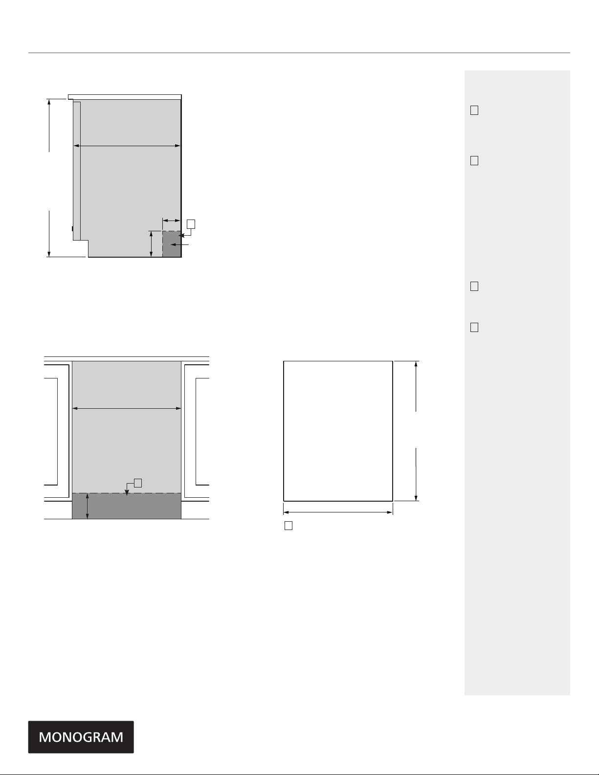
ZDT975SIJIIMONOGRAM 24" FULLY INTEGRATED DISHWASHER
ZDT870SIFII & ZDT800SIFII
INSTALLATION
33 1/2"
(85.1) min
underside of
counter to floor
34 3/4"
(88.3)
max
FLUSH CUTOUT INSTALLATION
24" (61.0)
min cutout depth
6"
(15.2)
24 " (61.0) Min
cutout width
4"(10.2)
B
ELECTRIC/
WATER
CUSTOM PANEL
29 13/16"
(75.7) min
30 1/4"
(76.8) max
NOTES
A
The dishwasher drain
hose must be no
more than 12 feet
in length for proper
drainage.
B
Electrical
connections are at
the right front of
the dishwasher and
water connections
are on the left. The
hot water line should
extend forward 30"
to 40" from the rear
wall. The electrical
must extend forward
at least 24" to reach
the junction box.
C
To prevent siphoning,
an air gap or high
drain loop must be
used.
D
A custom panel
installation
template (Part. No.
WD35X20417)
is available from
GE Parts and
Accessories
(US 800.626.2002,
Canada
800.561.3344).
B
6" (15.2)
ELECTRIC/
WATER
INSTALLATION CUTOUT FRONT VIEW
D
23 3/4" (60.3)
Product Specification Revised 8/16

ZDT975SIJIIMONOGRAM 24" FULLY INTEGRATED DISHWASHER
G
BL H D
BL
LGH D
MD M D
CUSTOM DISHWASHER DOOR PANEL TEMPLATE
GE PART NO. WD35X20417
Top of Panel Top of Panel
2-1/8” 2-1/8”
Trim Around Dotted Line
10-13/16”
Drill 3/32"
Pilot Hole
3/32" Deep
3/4" Thick Custom Panel
Template Instructions for
Top Control Integrated GE
Dishwasher Models
The custom panel should be sized to your installation situation. See Step 1.
It is highly recommended that the custom panel be attached before installing the dishwasher.
Use this template to locate mounting screws and spacers on the custom panel.
IMPORTANT
• A custom handle must be installed onto the
custom panel. Install the custom handle
4-1/2” max. from the top of the panel.
STEP 1 CUSTOM PANEL SIZE REQUIREMENTS
HEIGHT
Panel height must be between 29-13/16" and 30-1/4".
29-13/16” Min.
30-1/4” Max.
23-3/4”
• If the panel height is more than 30-1/4", it will
prevent the door from fitting under the cabinet.
• If the panel height is less than 29-13/16" it will not
cover the dishwasher door frame.
STEP 2 DRAW CENTERLINE
• Place the custom panel on a flat surface with appearance side down.
• Locate the vertical center of the panel at the top.
• Use a carpenters square to draw a centerline from top to bottom.
Side
Panel
of
Drill 3/32"
Pilot Hole
3/32" Deep
STEP 3 ALIGN TEMPLATE TO PANEL
25-5/16”
• Trim template on the dotted line along all sides.
• For Panel sizes 29-13/16” up to 30-1/16”, place template on the
panel aligned with the top edge and the centerline. Use tape to
hold in place.
• For Panel sizes over 30-1/16” up to 30-1/4”, place template on
the panel aligned with the bottom edge and the centerline. Use
tape to hold in place.
IMPORTANT: If the template is not aligned properly with the panel,
the panel may hit the toe kick and the door will not fully open.
Longer panels should overhang at the top of the door. Make sure
after installation, to maintain a minimum 1/8" gap to the countertop from the custom panel.
• Use an awl to mark the screw hole locations indicated on the
template. Remove the template.
STEP 4 INSTALL MOUNTING SCREWS AND SPACERS
If the panel is less than 3/4" thick, shorter screws must be used. Use
#8 x 3/4" screws for 1/2" thick panels (not supplied).
• Use a 3/32" drill bit to drill pilot holes 3/32" deep in the marked
locations. Make sure not to drill all the way through the panel.
Note: The custom panel is secured to the dishwasher door with the
spacers and screws provided. The 4 spacers will slip into the keyhole
slots on the dishwasher door.
• Drive the supplied #8 x 7/8” screws through the spacer and into
the panel.
• Install remaining spacers and screws as indicated in the marked
locations.
STEP 5 INSTALL CUSTOM HANDLE
A custom handle must be installed onto the panel before the panel is
secured to the dishwasher door.
• The handle should be installed so that it aligns with adjacent
drawer handles, or 4-1/2" max. from the top of the panel. Secure
the handle in the same manner as cabinet handles. Screws must be
countersunk into the panel.
STEP 6 INSTALL ASSEMBLED PANEL
• Secure the panel to the door by inserting the top and bottom
spacers into the matching keyhole slots.
• Make sure all 4 spacers engage the keyhole slots.
• Press the panel against the door and push downward until the
spacers are fully engaged into the keyhole slots. The panel should
align evenly with the top and sides.
Dimensions only used if aligning template with bottom
2-9/16”
of panel and length is between 30-1/16” to 30-1/4”.
Bottom of Panel Bottom of Panel
PARTS INCLUDED:
(4) Spacers
(2) #8 x 5/8” Phillips truss head stainless steel screws
(4) #8 x 7/8” Phillips truss head stainless steel wood screws
(2) Heavy duty springs
• The bottom of the custom panel must not overhang the
the bottom of the metal panel more than 3/16”. Exceeding
this will cause the custom panel to hit the toe kick and the
door will not fully open. Any extra length of the custom
panel must overhang at the top of the door.
WIDTH
Panel width must be 23-3/4".
• If the panel width is less than 23-3/4" it will not cover
the dishwasher door frame.
IMPORTANT: To ensure optimum door balance performance,
the custom panel must not weigh more than 20 lbs.
10” 10”
Trim Around Dotted Line
Align with this top edge only if panel is 29-13/16” up to 30-1/16”.
Countertop
1/2” min.
Minimum 1/2” gap
for clearance
FOR REFERENCE
ONLY
–
Mark Center
Screw Holes
NOT TO SCALE
Screw
Spacer
Screws Must
Be Countersunk
Into Panel
4-1/2" Max.
From Top
of Panel
Handle
Custom
Door Panel
Custom
Panel
Dishwasher
Door
Spacers
Engage Keyhole
Slots
Align with this bottom edge only if panel is between 30- 1/16” to 30-1/4”.
Trim Around Dotted Line
10-13/16”
STEP 6 INSTALL ASSEMBLED PANEL - (CONTINUED)
Due to the location of the screw holes and very limited space it will be very helpful to attach the screws to the driving bit
with tape to keep the screw from falling off inside the door while inserting down inside. Read and follow the steps below.
1. Insert one of the supplied
#8 x 5/8” truss head screws
through a piece of masking
tape.
CAUTION: It is extremely important that the 2 screws are driven into the wood panel through the metal door
assembly. This locks the vertical motion of the custom panel and if not secured the panel can come off the unit during
door opening/closing causing personal injury and damage to the panel.
4. Carefully open the door because door will likely be unbalanced.
Start insertion of driver at approximately 45 angle to clear the screw head past the hinge components, once the screw
head is clear, rock the driver forward to a vertical position. Proceed to drive the screw. Repeat procedure for the opposite
side.
45
1
Drive screw through the hole
hinge bracket and door into
the wood panel.
STEP 7 INSTALL DOOR SPRINGS
• Depending on the weight of the panel being used, additional springs may be needed to balance the door during
operation. If only one spring is being attached to the cable, the spring hook should be inserted into the middle hole
on the cable and the other end of the spring should be hooked over the lowest screw on the rear tub bracket as
shown below:
• If multiple springs are required on each side to balance the door, the spring hooks should be inserted into the top and
bottom holes on the cable as shown below:
• The bottom spring opposite end should be hooked over the lowest screw on the rear tub bracket. The top spring
hooks into the first available hole above the screw in the same rear tub bracket. See illustrations below.
• The following table may be used as a guideline regarding which springs to use, depending on the weight of the panel
being added. However, spring combinations may be adjusted based on personal preferences regarding door feel.
Note: For combinations requiring two different strength springs, the side used is unimportant and the table headings
below are for reference only. For example, a panel weighing 8 lbs would require two (2) gray springs and one (1) blue
spring. The gray springs may be installed on the left side and the blue spring on the right side, or the two gray springs
may be installed on the right side and the blue spring on the left.
Panel Weight (lbs) Left Side Springs Right Side Springs
0-5 Blue Blue
5-10 Gray x 2 Blue
10-15 Blue x 2 Black
15-20 Blue x 2 Black x 2
• Close and latch the door.
• Check door balance after custom panel is installed.
If the door drops open too fast, you may swap any of
the springs with the next heaviest spring as shown in
the table.
• Remove the rear screw-style leveling feet because of
spring interference.
2. Insert a minimum 2” long bit
into head and wrap tape around
end of bit. (#1 square drive
preferred)
NOTICE: Do not overtighten screws.
in
Excessive tightening of the screws
could damage door edges.
3. Use a bit extension with a
max 3/8” diameter shank
and a minimum 2-3/4”
length.
2
3
Inner Door
Spring Strength
Side View
Spring
hooked
to screw
inside leg
TIP: If the door does not open easily or falls too quickly, check
spring cable routing. The cable is held in place by “shoulders” on
the pulley. Check to be sure the cable has not slipped over the
pulley shoulders.
IMPORTANT: Adjust both balance springs to the same amount of
tension to prevent excessive door twisting during use.
Dimensions only used if aligning template with bottom
of panel and length is between 30-1/16” to 30-1/4”.
Trim Around Dotted Line
Door shown fully open
Custom
Panel
Hinge
Installed screw
Custom
door
panel
Front View
Make sure pulley cables
are within pulley shoulders
Pub no. 31-31511-2
01-14 GE
25-5/16”
2-9/16”
Drill 3/32"
Pilot Hole
3/32" Deep
Drill 3/32"
Pilot Hole
3/32" Deep
SPECIAL NOTES
The custom panel
and custom handle
of your choice should
be secured to the
dishwasher before
installation begins.
A template with
instructions and
installation hardware is
provided.
For planning purposes,
you may order the
template in advance
by calling
1.800.GE.CARES
(1.800.423.2737) or by
visiting our website at
GEAppliances.com in
the United States.
In Canada, call
1.800.561.3344
or visit
www.GEAppliances.ca.
Order Part No.
WD35X20417. Complete
panel installation
instructions are included
on the template.
Side
of
Panel
Maximum panel weight
is 20 LBS (9.1 kg).
CALL 1-800-626-2000
For a full-size panel template with complete panel installation instructions.
Product Specification Revised 8/16

FEATURES AND BENEFITS
MOST ADVANCED WASH SYSTEM WITH MORE
THAN 140 CLEANING JETS
Achieve the ultimate clean from an industry-leading
number of jets that deliver complete washing
coverage to every corner of the dishwasher
FULL-EXTENSION, SMOOTH-GLIDE, ADJUSTABLE
THIRD RACK
Functions as a utensil drawer for cleaning of an
entire flatware collection, along with carving knives,
soup ladles, tongs and other cooking/serving tools
DEEP CLEAN SILVERWARE JETS
Powerful jets blast away stuck-on food for
silverware that’s always spotless
BOTTLE JETS
Hard-to-reach areas inside tall items get completely
clean with four dedicated jets integrated into the
upper rack that shower water deep inside for the
ultimate clean
ZDT975SIJIIMONOGRAM 24" FULLY INTEGRATED DISHWASHER
LED LIGHTING
Illuminates the entire interior, leaving no question
as to whether or not dishes have been cleaned
39 DBA QUIET OPERATION
Is made possible by advanced sound-absorbing
materials and a smooth-running motor
CABINET DEPTH INSTALLATION
Customize this appearance with a panel to match
the décor of your kitchen - true flush capable, even
with inset cabinets
WIFI CONNECT
Monitor performance and check cycle status using
your mobile device
EASY TOUCH ADJUSTABLE UPPER RACK
WITH 2 STEM SAFE WINE GLASS HOLDERS
Quickly adjust the upper rack 2 inches up or down
to accommodate tall glassware and 10-1/2" plates
with plenty of room in the bottom rack for large
platters and cookie sheets
R
Product Specification Revised 8/16
 Loading...