

Monogram ZBD9900RII Technical Service Manual

GE Appliances
Technical Service Guide
March 2011
Monogram Dishwasher
with Top Controls
31-9207
ZBD9900RII
GE Appliances
General Electric Company
Louisville, Kentucky 40225

IMPORTANT SAFETY NOTICE
The information in this service guide is intended for use by
individuals possessing adequate backgrounds of electrical,
electronic, and mechanical experience. Any attempt to repair a
major appliance may result in personal injury and property
damage. The manufacturer or seller cannot be responsible for the interpretation of this information, nor can it assume any liability in connection with its use.
WARNING
To avoid personal injury, disconnect power before servicing
this product. If electrical power is required for diagnosis or test
purposes, disconnect the power immediately after performing the
necessary checks.
RECONNECT ALL GROUNDING DEVICES
If grounding wires, screws, straps, clips, nuts, or washers used
to complete a path to ground are removed for service, they must
be returned to their original position and properly fastened.
All rights reserved. This service guide may not be reproduced in whole or in part ,
in any form, without written permission from the General Electric Company.
GE Appliances
Technical Service Guide
Copyright © 2011
– 2 –

TABLE OF CONTENTS
Air Gap and Flow Meter .................................................................................................................................................31
Back Access Panel ............................................................................................................................................................27
Circulation Pump ...............................................................................................................................................................31
Component Locator Views ..........................................................................................................................................16
Control Panel Features ................................................................................................................................................... 8
Control Interface ...............................................................................................................................................................22
Detergent/Rinse Aid .........................................................................................................................................................24
Dishwasher Components ..............................................................................................................................................19
Door Hinge ...........................................................................................................................................................................25
Door Springs........................................................................................................................................................................25
Door Vent Fan .....................................................................................................................................................................24
Drain Pump ..........................................................................................................................................................................34
Drain Pump Check Valve ...............................................................................................................................................34
EMI Filter ................................................................................................................................................................................33
Escutcheon ..........................................................................................................................................................................21
Fault Codes .........................................................................................................................................................................36
Flow Meter ..........................................................................................................................................................................31
Heater ....................................................................................................................................................................................32
Inner Door Panel ...............................................................................................................................................................25
Inside Tub Components .................................................................................................................................................26
Installation ........................................................................................................................................................................... 7
Introduction ........................................................................................................................................................................ 6
Latch Assembly .................................................................................................................................................................23
Light Switch .........................................................................................................................................................................34
Lower Frame .......................................................................................................................................................................30
Main Control ........................................................................................................................................................................22
Main Control Programs ..................................................................................................................................................36
Main Control Testing........................................................................................................................................................21
Main ON/OFF Switch .......................................................................................................................................................22
Mini Manual Location ...................................................................................................................................................... 5
– 3 –
(Continued next page)

Nomenclature .................................................................................................................................................................... 5
Outer Door Panel ..............................................................................................................................................................20
Overfl ow Cut Out ..............................................................................................................................................................33
Pressure Sensor .................................................................................................................................................................29
Schematic.............................................................................................................................................................................42
Service Mode ......................................................................................................................................................................35
Special Tool ..........................................................................................................................................................................19
Thermistor ............................................................................................................................................................................33
Toe Kick Plate ......................................................................................................................................................................32
Troubleshooting ................................................................................................................................................................35
Troubleshooting Check List ..........................................................................................................................................37
Turbidity Sensor ................................................................................................................................................................32
Upper Basket ......................................................................................................................................................................19
Warranty ..............................................................................................................................................................................43
Washability Complaints ...............................................................................................................................................41
Water Level - How Does It Work? .............................................................................................................................28
Water Valve .........................................................................................................................................................................29
– 4 –
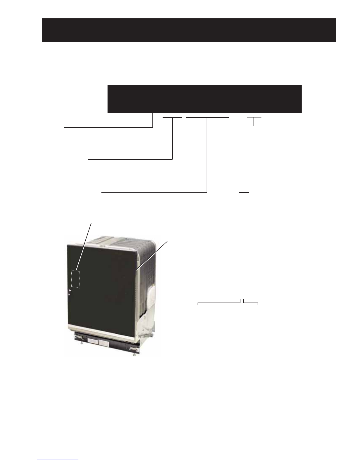
Model Number
Nomenclature
Z B D 9 9 0 0 R I I
Brand
Z = Monogram
Product Type
BD = Built-In Dishwasher
Model Designator
Mini Manual
Exterior Color
SS = Stainless Steel
BB = Black
WW = White
II = Custom panel and handle
required
Model Year Designator
Nomenclature
Serial Number
The fi rst two characters of the serial number
identify the month and year of manufacture.
Example: FV123456S = March, 2011
The serial plate of your dishwasher
is located on the tub wall, just
outside the door.
The mini manual is located on the
inside of the outer door panel.
– 5 –
F - MAR
G - APR
H - MAY
L - JUN
M - JUL
R - AUG
S - SEP
T - OCT
V - NOV
Z - DEC
A - JAN
B - FEB
2011 - V
2010 - T
2009 - S
2008 - R
2007 - M
2006 - L
2005 - H
2004 - G
2003 - F
2002 - D
2001 - A
2000 - Z
The letter des ig nat ing
the year re peats every
12 years.
Example:
V - 2011
V - 1999
V - 1987

Introduction
bask
The new Monogram dishwasher is a brand new design with these
following features:
• Hidden touch pad control panel on the top edge of the tall front door
• Larger tub with a height-adjustable upper basket and new cutlery
basket
• New location for inlet valve, fl ow meter, and pressure sensor
• New dishwashing programs
• New Diagnostics to aid in troubleshooting problems
• New water level control
1. Upper
et
2. Spray arms
3. Lamp
4. Cutlery basket
5. Lower basket
6. Dishwasher detergent compartment
7. Main power switch
8. Rinse Aid Compartment
9. Filter
10. Rating plate
1
2
4
3
3
5
6
7
8
9
10
– 6 –
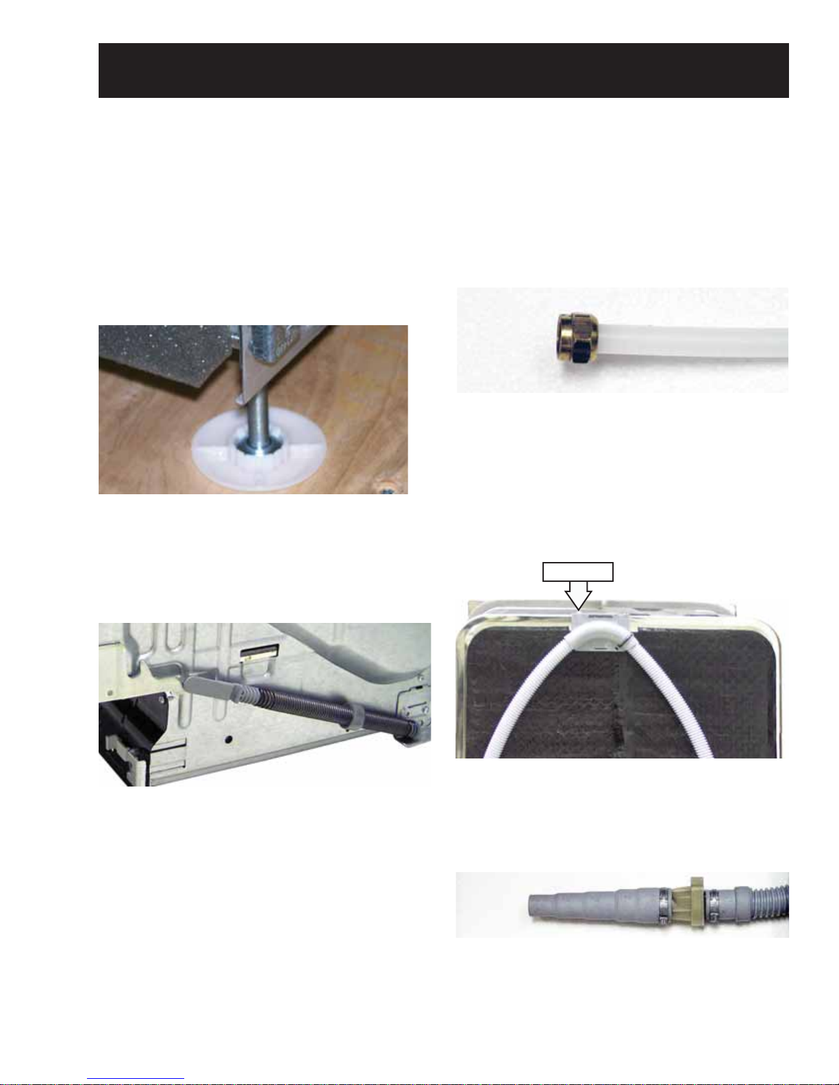
Installation
The installation manual and hardware packet are
located inside the machine. The toe kick plate
comes packaged on the top of the Styrofoam
packaging inside the shipping carton.
Snap the plastic glide feet onto the leveling legs to
prevent damage to the fl oor. Please note that the
unit weight is 101 lbs. and the glide feet can mar
some soft wood fl oors. Caution should always be
used when moving a unit into place.
Adjust the door springs
The door should remain balanced once opened.
Both spring ends are turned clockwise to increase
tension, and counterclockwise to decrease tension.
PEX water fi ll line
The PEX water fi ll line comes with a 3/8-in.
compression nut that is intended to be connected
to a shutoff valve with compression threads. If the
home shutoff valve has a solder fi tting, cut the
copper water line under the sink and join the copper
and PEX materials with a 3/8-in. compression union.
Drain line
The high loop bracket comes attached to the unit at
the ideal height. It should not be removed.
The drain line bracket can be repositioned to
accommodate an installation or gain hose length
by loosening the set screw and sliding the bracket
along the back top ridge.
Set Screw
Specifi cations
Height
Width
Depth
Weight
Water Pressure
Connection
Max output
33-7/8" _ 36"
23 5/8"
22 7/8" (without door)
101 lbs
4.2 _ 140 psi
0.03 _ 1.0 Mpa
0.3 _ 10 Bar
Single phase, 120 V, 60 Hz, 15 A
1200 W
The drain line comes with a graduated boot
installed. This graduated boot is designed to
accommodate 1/2-, 5/8-, 23/32-, and 7/8-in.
connections.
The power cord (approximately 42-in. long) comes
already attached to the unit. The terminal block is
set up so that the unit can be hardwired or a longer
cord installed if needed.
– 7 –
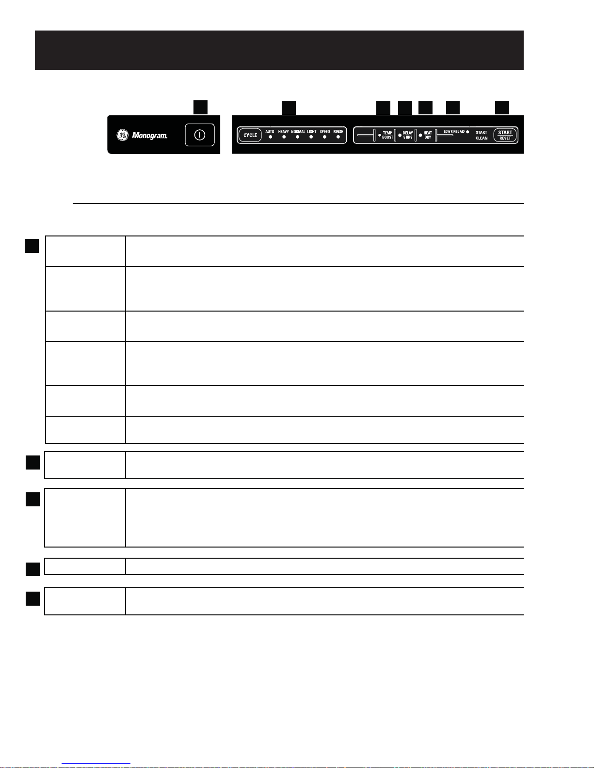
Control Panel Features
7
Select a cycle by pressing the CYCLE button until the required option is selected.
1
AUTO WASH
HEAVY WASH
NORMAL
WASH
LIGHT WASH
The dishwasher detects how soiled the dishes are and adjusts water
consumption and temperature accordingly.
The HEAVY WASH program should be used for heavily soiled dishes, e.g.
saucepans, pots and gratin dishes. If there is still space in the machine after
loading such items, you can add plates etc.
Used for washing normally soiled dishes such as plates, serving dishes, cups and
glasses, etc.
If the dishes are not heavily soiled, you can select the Light Wash cycle. This
cycle is intended for glass and china which has just been used and therefore
does not need a more powerful cycle.
1
2 3
4 5 6
SPEED WASH
RINSE ONLY
2
TEMP BOOST
3
DELAY START
HEAT DRY Select this option to improve drying results.
4
LOW RINSE
5
AID
Select SPEED WASH if the dishes are very lightly soiled. This program is used for
very lightly soiled glass and china, e.g. coffee cups.
For rinsing partial loads that will be washed later. Do not use detergent with this
cycle.
When selected, the cycle will run with a heating element on longer and may
increase cycle time to improve both wash and dry performance.
If you want the machine to start later, press the DELAY START option button. The
clock symbol on the button lights up. Then press the START/RESET button and
the machine will start the program 5 hours later. To cancel DELAY START, hold
down the START/RESET button for three seconds.
Displayed when the rinse agent dispenser needs to be refilled.
– 8 –
(Continued next page)
PROGRAMS
Average Total
Cycle Time (Min)
Water Consumption
(Gallons)
Auto 115 - 170 3.4 - 6.3
Heavy 190 - 210 5.3
Normal 105 - 140 4.0 - 5.8
Light 100 - 127 2.9
Speed 20 - 64 2.6
Rinse 4 - 22 0.8
– 9 –
(Continued next page)
Lighting
Features
Interior Lights
The interior Halogen lights provide better visibility
for loading and unloading. They turn on when
the door is opened and turn off when the door is
latched.
Do not attempt to replace the bulbs. If light bulb
replacement is necessary, please contact the
GE Answer Center for service by calling
1.800.626.2000.
Water
Temperature
Use a
Rinse
Agent
The entering water must be at least 120°F (49°C)
not more than 150°F (66°C), for effective
and
cleaning and to prevent dish damage.
Check the water temperature with a candy or
meat thermometer. Turn on the hot water faucet
nearest the dishwasher, place the thermometer in
A rinse agent improves dry performance,
reduces spots and prevents new film buildup
on your dishes, glasses, flatware, cookware
and plastic. Cascade Crystal Clear
recommended rinse agent for Monogram
Dishwashers.
The rinse agent dispenser holds 4.7 o]. of rinse
agent. Under normal conditions, this will last
approximately one month. Try to keep it full,
but do not overfill.
To fill the rinse agent dispenser, make sure the
dishwasher door is fully open.
®
is the
a glass and let the water run continuously into the
glass until the temperature stops rising.
NOTE: This Dishwasher can be plumbed to the
cold water faucet, but this is not recommended.
Rotate the dispenser cap counterclockwise and
lift it out. Add rinse agent until the indicator
window shows full.
Clean up any spilled rinse agent with a damp
cloth. Replace the dispenser cap.
The amount of rinse agent released into the final
wash can be adjusted. The factory setting is at
the midpoint. If there are rings of calcium (hard
water) spots on dishes, try a higher setting. If
there is foaming, use a lower setting.
To adjust the setting, remove the dispenser
cap; then turn the adjuster counterclockwise to
increase the amount of rinse agent or clockwise
to decrease the amount of rinse agent dispensed.
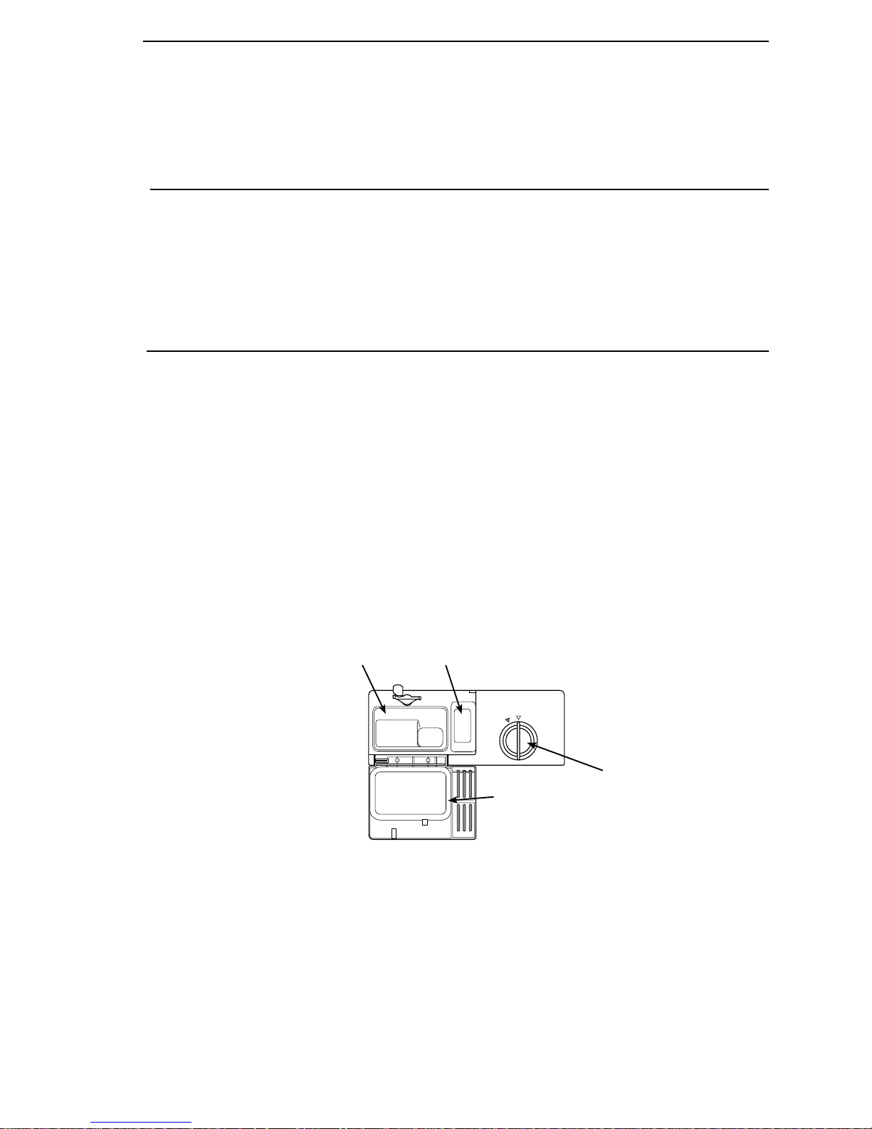
1. Compartment for main wash dishwasher
1. Compartment for main wash dishwash-
detergent
er detergent
2. Compartment for pre-wash detergent
2. Compartment for pre-wash detergent
3. Rinse aid cover
3. Rinse aid cover
4. Detergent compartment cover
4. Detergent Compartment cover
1
2
3 (Rinse agent adjuster
4
is located under the cap)
– 10 –
(Continued next page)
Detergent Dosage
Recommended Detergent Amounts based on Water Hardness
Water hardness Detergent amounts
Soft
(0-3 grains per gallon)
Medium
(4-8 grains per gallon)
hard
(9+ grains*)
* 12 grains and higher is extremely hard water.
Prewash 1 teaspoon
Main wash 1 to 1-1/2 tablespoons
Prewash 1 teaspoon
Main wash 1 to 2 tablespoons
Prewash 1 teaspoon
Main wash 2 to 3 tablespoons
The dishwasher’s inner container is made of
stainless steel and is kept clean through normal use.
However, if you have calciferous (hard) water, lime
deposits can form in the dishwasher. In this case,
run a normal wash program with two tablespoons
of citric acid in the dishwasher detergent
compartment.
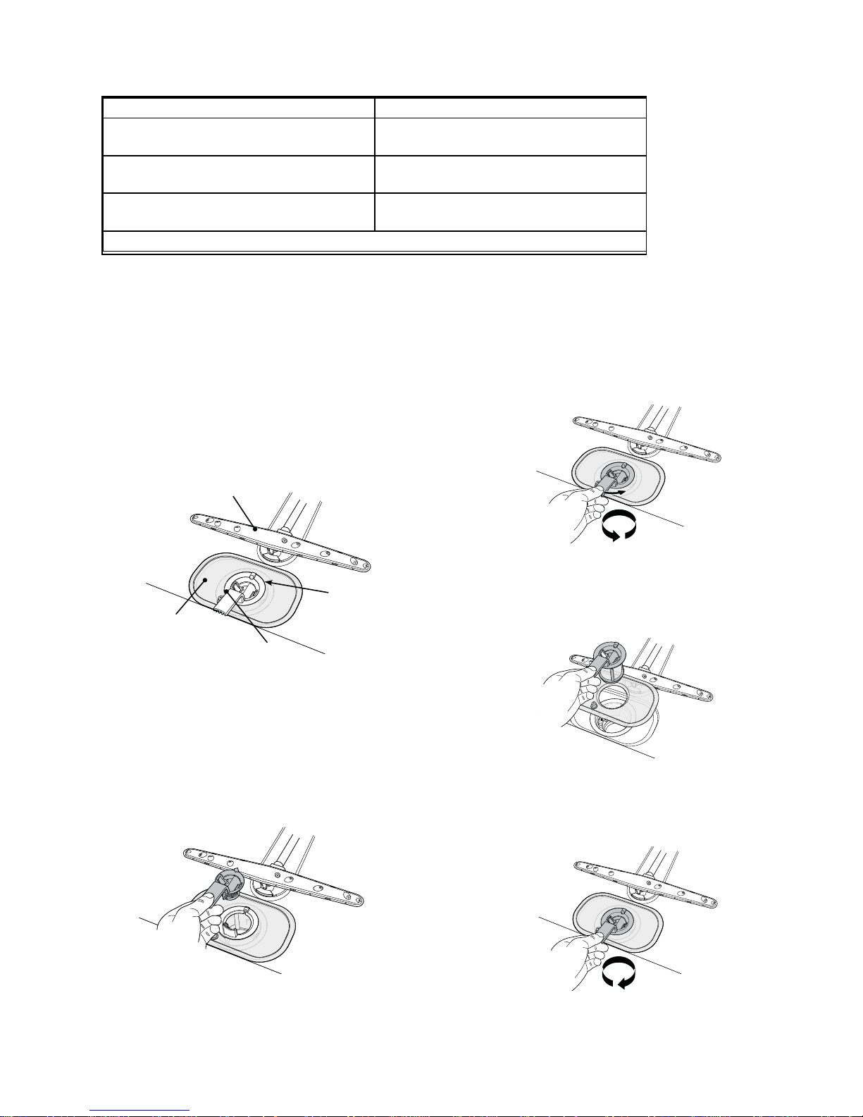
Filters
The dishwasher utilizes a coarse fi lter and a fi ne
fi lter.
Fine ¿lter
Spray arm
Coarse ¿lter
Tubular
strainer
Coarse fi ler
fi lter and its pipe section should be cleaned once or
twice a year.
1. Turn the handle 1 full turn counterclockwise.
2. Lift the pipe section straight up by the handle
and then lift the coarse fi lter to clean the pipe
section.
1x
3. Remove and clean the fi ne fi lter.
4. Replace in reverse order. Ensure that the edges
are properly sealed when replacing the fi ne fi lter.
The coarse fi lter traps lager food particles, which
cannot get past the drain pump. Empty the coarse
fi lter as necessary.
1. Lift the coarse fi lter by the handle
2. Empty the coarse fi lter and replace it.
Fine fi ler
Debris that collects on the fi ne fi lter is aumatically
rinsed away during each wash. However, the fi ne
5. Lock the fi lter in place by turning the handle
clockwise to the stop position. The handle should
point out from the dishwasher.
1x
Note: The dishwasher must not be used without the
fi ler in place! An improperly fi tted coarse fi lter may
affect the dishwashing result.
– 11 –
(Continued next page)
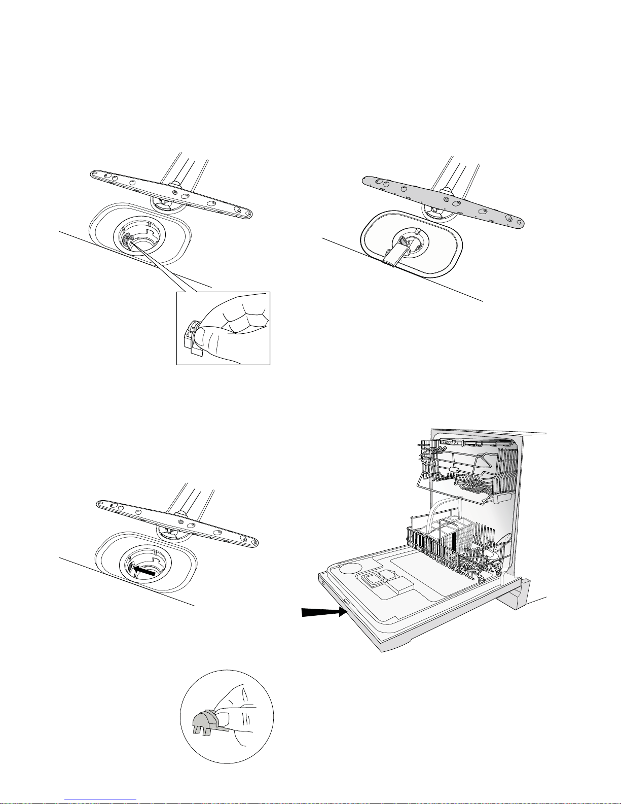
Drain pump
The spray arms
The pump can be accessed from inside the machine.
WARNING: Disconnect the power from the machine
1. Remove the coarse fi lter and pipe section.
2. Remove the small fi tted piece at the left of the
sump (see the image below).
3. The impeller blade can be checked and accessed
from inside this sump opening.
Holes and bearings can sometimes become blocked.
1.
Pull the lower washer arm straight up to release it.
2. Remove any deposits. The washer arms also
have holes underneath.
3. Reassemble the washer arm before using the
dishwasher.
Door
When cleaning the edge around the door, use a
slightly damp cloth. Do not use a spray bottle
around the door catch. This is to ensure that water
does not come into contact with the electrical
components in the door catch.
4. Reinstall the fi tted piece and fi lters.
5. Insert the plug into the wall socket.
If the machine still does not start and a buzzing
sound is heard, the overfl ow guard has been
activated.
• Shut off the water.
• Pull the plug out from the
wall socket.
• Call for service.
Note: Be sure to reinstall the
fi tted piece.
– 12 –
(Continued next page)
Program Selection
Some of the dishwasher’s programs can changed by using the keypad. The new selection will be retained
until the next time you use the keypad to reset this function.
Even if the machine is turned off at the main switch or loses power for any other reason, all selections
registered before the interruption of power will be retained.
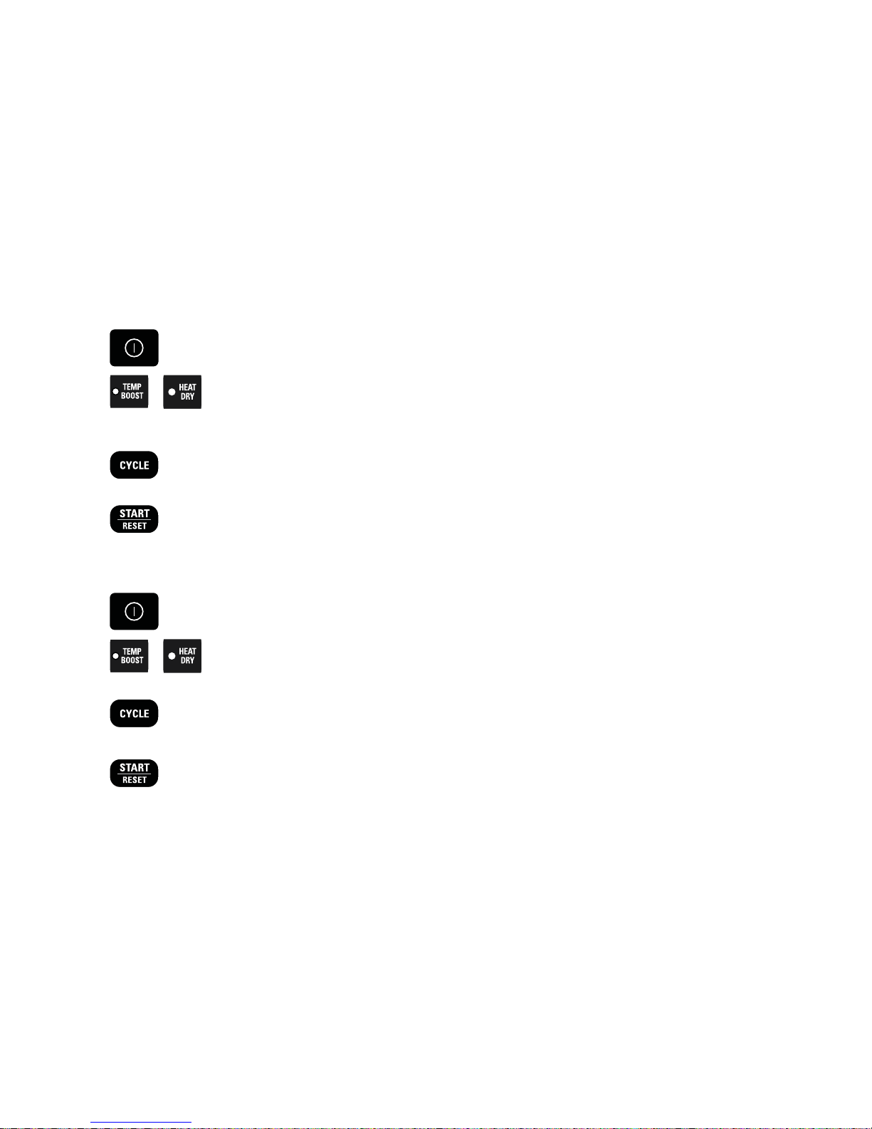
Child-safe button lock
You can prevent a child starting the machine by accident or changing the settings by programming
the machine with a button lock, which requires the TEMP BOOST and HEAT DRY buttons to be pressed
simultaneously to start up the machine. The button lock will automatically be reactivated after 3 minutes.
1. Switch off the dishwasher with the main switch.
2. Hold in the TEMP BOOST and HEAT DRY buttons while pressing the main
switch. The Temperature, Drying, and Start symbols will fl ash. Release the
TEMP BOOST and HEAT DRY buttons.
3. Press the CYCLE button – when the AUTO wash symbol is lit, the button lock
has been activated.
4. Then press the START/RESET button to store the setting.
or Reset:
1. Switch off the dishwasher with the main switch.
2. Hold in the TEMP BOOST and HEAT DRY buttons at the same time as
pressing the main switch.
3. Press the CYCLE button – when the AUTO wash symbol goes out, the button
lock has been deactivated.
4. Then press the START/RESET button to confi rm the setting.
– 13 –
(Continued next page)
 Loading...