

Page 1
MONOGRAM 18" DISHWASHER ZBD1850NII
ZBD1850NII
ZBD1850NII
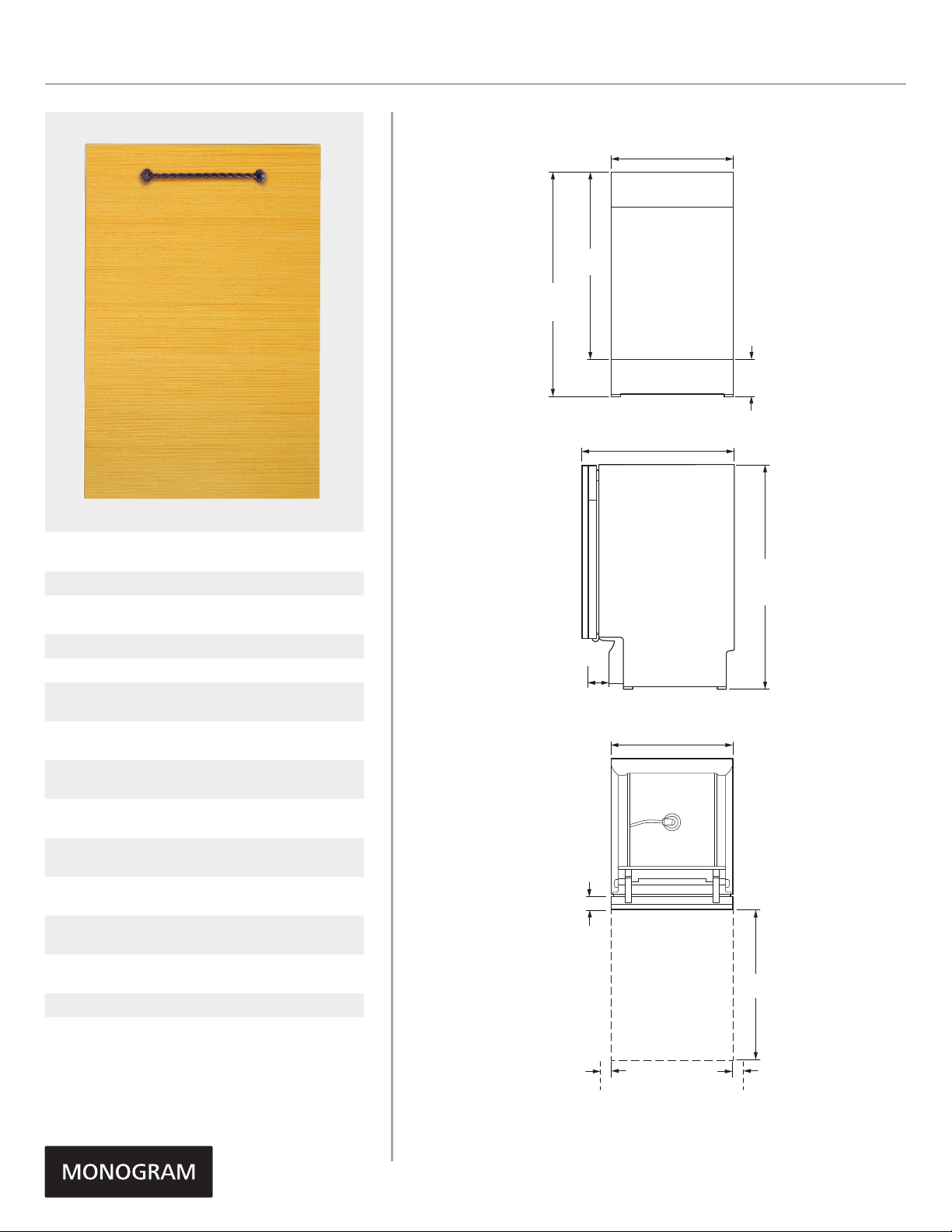
OVERALL DIMENSIONS
17 1/2" (44.5)
26 13/16"
(68.0)
32 1/2" min
35" max
(82.5 - 88.9)
FRONT VIEW
22 1/2" (57.2)
5 11/16" min
8 3/16" max
(14.5 - 20.9)
Toe kick
height
SPECIFICATIONS
Overall Width 17 1/2" (44.5 cm)
Overall Height
Overall Depth 22 1/2" (57.2 cm)
Door Clearance 25 5/8" (14.3 cm)
Overall Dishwasher
Capacity
Minimum Cabinet
Width
Minimum Cabinet
Depth
Cutout Width
Cutout Height
Electrical
Requirements
Hose Length
Voltz/Hertz/Amps
Shipping Weight 78 lb (35 kg)
32 1/2" (82.6 cm) Min
35" (88.9 cm) Max
8 Place Settings
17 5/8" (44.8 cm)
24" (61 cm)
17 5/8" (44.8 cm) Min
18" (45.7 cm) Max
32 1/2" (82.6 cm) Min
35" (88.9 cm) Max
9.0 A
No more than
10' (3 m)
115 V, 60 Hz,
15 or 20 amp circuit
3"
(7.6)
2" (5.1)
SIDE VIEW
17 1/2" (44.5)
TOP VIEW
OPEN DISHWASHER
DOOR SHOWING
DOOR CLEARANCE
32 1/2" min
35" max
(82.6 - 88.9)
Height at rear
25 5/8"
(65.1)
2" (5.1)
min
clearance
to wall
Dimensions in parentheses are in
centimeters unless otherwise noted.
2" (5.1)
min
clearance
to wall
Product Specification Revised 7/16
Page 2
ZBD1850NIIMONOGRAM 18" DISHWASHER
ZBD1850NII
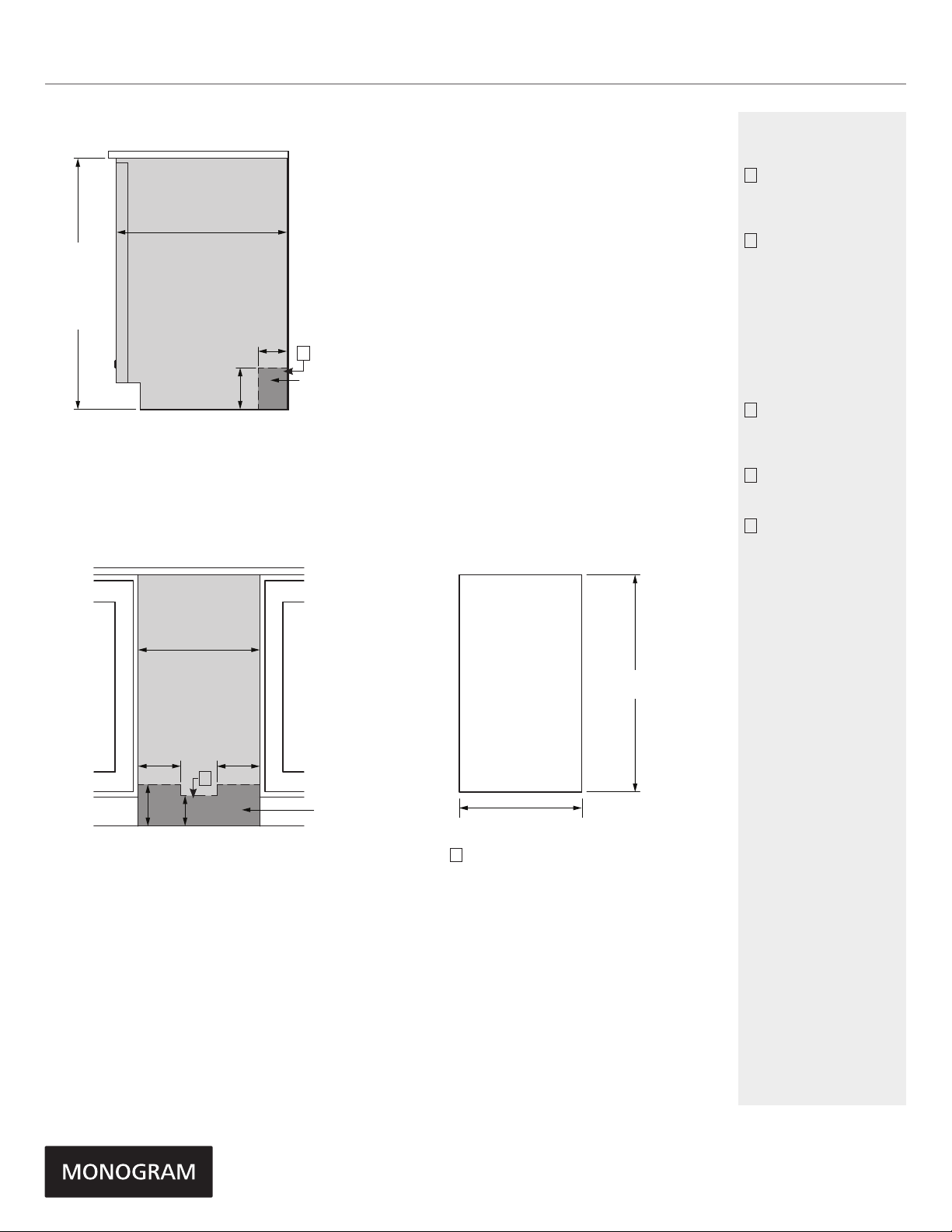
INSTALLATION
32 1/2"
(82.55) min
underside of
counter to floor
Can be adjusted
up to 35" (88.9)
FLUSH CUTOUT INSTALLATION
24" (61.0)
min cutout depth
6"
(15.2)
17 5/8" (44.8) Min
cutout width
18" (45.7) Max
cutout width
4"(10.2)
C
ELECTRIC/
WATER
CUSTOM PANEL
26 13/16"
(68.0)
NOTES
A
The dishwasher drain
hose must be no more
than 10 feet in length
for proper drainage.
B
A reduced-height
installation (32-1/2"
min.) beneath a 34"
countertop can be
accomplished by
screwing in the rear
legs flush with the
bottom support,
removing the front
leveling legs and
adding shims to level.
C
Water and electrical
must be routed
through the back wall
shown in shaded area.
D
To prevent siphoning,
an air gap or high drain
loop must be used.
E
A custom panel
installation template
(Pub. No. 31-30244)
is available from
GE Parts and
Accessories
(US 800.626.2002,
Canada 800.561.3344).
5"
(12.7)
5"
(12.7)
C
6" (15.2) 4" (10.2)
INSTALLATION CUTOUT FRONT VIEW
ELECTRIC/
WATER
17 1/2" (44.5)
E
Product Specification Revised 7/16
Page 3

ZBD1850NIIMONOGRAM 18" DISHWASHER
Instructions de gabarit pour panneau
sur mesure épais de 19 mm (3/4 po)
pour modèle de lave-vaisselle à réglage
intégré en haut Prole et Monogram
Le panneau de nition doit avoir des dimensions appropriées pour l’installation. Consulter l’étape 1.
Pour faciliter l’installation, le panneau de nition et la poignée de nition doivent être montés avant la mise
en place du lave-vaisselle. Utiliser ce gabarit pour déterminer l’emplacement des vis de montage et
des rondelles sur le panneau de nition.
IMPORTANT
le panneau de nition. Installer la poignée à
moins de 11,5 cm (4-1/2 po) du haut du pan-
neau.
ÉTAPE 2 TRAÇAGE DE L’AXE
• Mettre le panneau de sur une surface plate, le côté extérieur
vers le bas.
• Mettre le centre vertical du panneau en haut.
• Avec une équerre de menuisier, tracer un axe du haut au bas.
ÉTAPE 4 INSTALLER LES VIS DE MONTAGE ET LES RONDELLES
• Couper le gabarit suivant le pointillé, sur tous les côtés.
• Mettre le gabarit sur le panneau, aligné sur le bord supérieur et sur l’axe.
Le maintenir en place avec du ruban adhésif.
IMPORTANT : Si le gabarit n’est pas aligné à l’extrémité du haut du panneau,
vous n’obtenez pas 1/2 po d’espace libre. Vous devez avoir un espace libre de
1/2 po pour empêcher la condensation et éviter d’endommager le panneau de
contrôle avec les têtes de vis.
• Avec un pointeau, marquer les emplacements de trous de vis indiqués
sur le gabarit. Enlever le gabarit.
HAUTEUR
Le panneau doit avoir entre au moins 30 1/16 po et 30 1/4 po
de hauteur.
• Si le panneau a plus de 30 1/4 po de hauteur, il empêche la
porte de s’ouvrir complètement.
• Si le panneau a moins de 30 1/16 po de hauteur, il ne couvre
pas le châssis de porte du lave-vaisselle.
PIÈCES INCLUSES :
(4) Rondelles
(4) Vis nº 8 x 5/8 po à tête bombée Phillips, en acier inoxydable
(3) Vis à bois nº 8 x 1-3/4 po à tête bombée Phillips, en acier
inoxydable
(2) Ressorts pour service sévère
ÉTAPE 1TAILLE NÉCESSAIRE POUR LE PANNEAU SUR MESURE
Si l’épaisseur du panneau est inférieure à 19 mm (3/4 po), il faut utiliser des vis
plus courtes. Utiliser des vis nº 8 x 1/2 po (pas fournies) pour les panneaux de
13 mm (1/2 po).
• Utiliser une mèche de 2,4 mm (3/32 po) pour percer des trous guides à une
profondeur de 2,4 mm (3/32 po) aux emplacements marqués.
Remarque : Le panneau de est mainten u en place sur la porte du lave-
vaisselle avec des rondelles et des vis fournies. La rondelle glisse dans les
trous allongés dans la porte du lave-vaisselle.
• Visser les vis nº 8 x 5/8 po à tête bombée Phillips, en acier inoxydable(four-
nies) à travers la rondelle et dans le panneau.
• Installer les rondelles et les vis restantes, comme indiqué, aux endroits mar-
qués.
IMPORTANT : Pour que la porte fonctionne
bien, le panneau sur mesure ne doit pas
peser plus de 6,4 kilos (14 livres).
ÉTAPE 3 ALIGNER LE GABARIT SUR LE PANNEAU
• Le haut du panneau sur mesure doit le haut de la
porte. Il doit y avoir un espace libre d’au moins 1/2 po en-
tre le haut de la porte et le bas du revêtement de comptoir.
LARGEUR
Le panneau doit avoir au moins 23 3/4 po de largeur.
• Si le panneau a moins de 23 3/4 po de largeur, il ne couvre
pas le châssis de porte du lave-vaisselle.
CUSTOM DISHWASHER DOOR PANEL TEMPLATE
GE PUB. NO. 31-30244
Top of Panel
2-5/32"
Drill 3/32"
Pilot Hole
3/32" Deep
(5.5 cm)
7-11/16"
(19.5 cm)
3/4" Thick Custom Panel
Template Instructions for 18"
Top Control Integrated Prole and
Monogram Dishwasher Models
The custom panel should be sized to your installation situation. See Step 1. For easier
installation, the custom panel and custom handle should be attached before installing the
dishwasher. Use this template to locate mounting screws and spacers on the custom panel.
IMPORTANT
• A custom handle must be installed onto the custom
panel. Install the custom handle 4-1/2" max. from
the top of the panel.
STEP 1 CUSTOM PANEL SIZE REQUIREMENTS
HEIGHT
Panel height should be 26-25/32" (68 cm).
• The top of the custom panel must be
with the top of the door. The 1/2" minimum gap
between the top of the door and the bottom of
the countertop must be maintained.
Minimum 1/2" gap
for clearance
STEP 2 DRAW CENTERLINE
• Place the custom panel on a surface with the
appearance side down.
• Locate the vertical center of the panel at the top.
• Use a carpenter's square to draw a centerline from
top to bottom.
STEP 3 ALIGN TEMPLATE TO PANEL
• Trim template on the dotted line along all sides.
• Place the template on the panel aligned with the top
edge and the centerline. Use tape to hold in place.
IMPORTANT: If the template is not aligned with the top
edge of the panel, the 1/2" minimum gap will not be maintained.
This 1/2" minimum gap must be maintained to prevent condensation
and damage to the control panel from screw heads.
• Use an awl to mark the screw hole locations indicated
on the template. Remove the template.
13/32"
(1 cm)
6-1/2"
(16.5 cm)
PARTS INCLUDED:
(2) Brackets
(4) 1/2" Phillips at-head screws
(2) Spacer pads
(2) Metal spacers
(2) 1" Phillips at-head screws
(2) 3/4" Phillips round-head screws
WIDTH
Panel width must be 17-1/2" (44.4 cm).
•If the panel width is less than 17-1/2", it will
not cover the dishwasher frame.
IMPORTANT: To ensure optimum door balance
performance, the custom panel must not weigh
more than 8 lbs.
Countertop
1/2" minimum
Drill 3/32"
Pilot Hole
3/32" Deep
Trim Around Dotted Line
FOR REFERENCE
5-29/32"
(15 cm)
STEP 4 INSTALL MOUNTING SCREWS AND SPACERS
Note: The custom panel is secured to the dishwasher door
with the metal spacers, screws and brackets provided.
The metal spacers and brackets will slip into the slots
on the dishwasher door and control panel.
• Align the metal spacers over the top pilot holes. Ensure
the thick, recessed side is facing up.
• Drive the supplied 1" Phillips screws through
the metal spacers and into the panel.
• Align the brackets over the bottom pilot holes. Ensure
the curved lip is facing up. If the back surface of the
panel is not use the spacer pads provided.
• Drive the 1/2" Phillips screws through the
brackets and into the panel.
STEP 5 INSTALL CUSTOM HANDLE
A custom handle must be installed onto the panel
before the panel is secured to the dishwasher door.
• The handle should be installed so that it aligns with
adjacent drawer handles, or 4-1/2" max. from the
top of the panel. Secure the handle in the same
manner as the cabinet handles. Screws must be
countersunk into the panel.
STEP 6 INSTALL ASSEMBLED PANEL
• Secure the panel to the door by inserting
the top metal spacers and bottom brackets
into the matching slots on the dishwasher
door and control panel.
• Make sure both metal spacers and both
brackets engage the slots.
• Press the panel against the door and push
downward until the metal spacers and brackets
are fully engaged into the slots. The panel should
align evenly with the top and sides.
• Stand the dishwasher upright.
• Open the dishwasher door and remove the
ONLY
NOT TO SCALE
Mark center
screw holes
2 plug buttons, one on each side as shown.
• Place the supplied 3/4" Phillips round-head
screws inside the plastic sleeve and drive
–
through the inner door and into the custom
panel.
• Replace th e 2 plug buttons by pressing them
back into the plastic sleeve.
WARNING: Do not overtighten screws. Excessive
tightening of the screws could damage door edges.
STEP 7 CHECK DOOR BALANCE
To check the door balance, hold the top of the
dishwasher
• Check the door balance by opening and closing
the door.
• If the door drops when released, increase the
spring tension. If the door rises when released,
decrease the spring tension.
• Using a T25 torque driver, adjust in the direction
shown. Adjust both sides equally.
PARTS SUPPLIED
(2) 3/4" Round-head
screws
5-29/32"
(15 cm)
(2) Brackets(2) Spacer Pads
(4) Phillips at-head
screws
Top of Panel
7-11/16"
(19.5 cm)
Dishwasher door
Custom
panel
(2) Phillips at-head
screws
CALL 1-800-626-2000
Spacer Pad
Screws must be countersunk into panel
Custom
door panel
Custom panel
Increase
Drill 3/32"
Pilot Hole
3/32" Deep
(2) Metal spacers
Bracket
Decrease
Handle
6-1/2"
(16.5 cm)
2-5/32"
(5.5 cm)
Drill 3/32"
Pilot Hole
3/32" Deep
Spacer
4 1/2" Max.
from top
of panel
Trim Around
Dotted Line
Increase
Decrease
13/32"
(1 cm)
Pub. No. 31-30244
Dwg. No. 206C1559P182
05-08 JR
SPECIAL NOTES
The custom door
panel and custom
handle of your choice
should be secured
to the dishwasher
before installation
begins. A template
with instructions and
installation hardware is
provided.
For planning purposes,
you may order the
template in advance
by calling
1.800.GE.CARES
(1.800.423.2737) or by
visiting our website at
GEAppliances.com in
the United States.
In Canada, call
1.800.561.3344
or visit
www.GEAppliances.ca.
Order Pub. No.
31-30244. Complete
panel installation
instructions are included
on the template.
Maximum panel weight
is 8 LBS (3.6 kg).
For a full-size panel template with complete panel installation instructions.
Product Specification Revised 7/16
Page 4

FEATURES AND BENEFITS
CUSTOM PANEL MODEL
Designed for personalization with customersupplied cabinet-compatible panel and
custom handle
HIDDEN, INTEGRATED ELECTRONIC CONTROLS
Allow easy activation of wash cycles: heavy wash,
normal wash, light wash, china and rinse only
FIVE-LEVEL WASH SYSTEM
Provides eective, yet quiet cleaning power
PEARLESCENT GRAY RACKS WITH
BALL-TIPPED TINES
Provide plenty of space and loading flexibility
STEM SAFE SHELF
Allows for odd-shaped items and delicate stemware
ZBD1850NIIMONOGRAM 18" DISHWASHER
R
Product Specification Revised 7/16
 Loading...