

Page 1

TM
7541 85754110200
Tom Daniel's
GRIM REAPER
Today the “old school” chopper is hotter than
ever. Now, the Baddest of the Bad custom
old school choppers is back. Tom Daniel’s
righteous designed Grim Reaper (1974) still has
the “look”, 40 years after it was first designed.
The Grim Reaper starts with far-out raked
custom square-tubular forks with cool dualsquare headlights. Then there’s the “coffin”
shaped gas tank on the custom frame with his
‘n hers custom stitched seat, sissy bar and “Iron
Cross” medallion. It’s powered by a classic
V-twin motor with down-swept chrome pipes. A
tight, mean, classic looking Hog. ….Let’s RIDE!
READ THIS BEFORE YOU BEGIN
* Study the assembly drawings.
* Each plastic part is identified by a number.
* In the assembly drawings, some parts will
be marked by a star H to indicate chrome
plated plastic.
* For better paint and decal adhesion,
wash the plastic parts in a mild detergent
solution. Rinse and let air dry.
* Check the fit of each piece before
cementing in place.
* Use only cement for polystyrene plastic.
* Scrape plating and paint from areas to
be cemented.
* Allow paint to dry thoroughly before
handling parts.
* Any unused parts may be discarded.
Aujourd'hui, les choppers de la vieille école sont plus
populaires que jamais. Et aujourd'hui, le meilleur des
choppers classiques est de retour. Le Grim Reaper
(1974), une création de Tom Daniel, a toujours de la
gueule, 40 ans après sa création. Le Grim Reaper utilise
de longues fourches tubulaires carrées et deux phares
carrés tendance. Il y a aussi le réservoir d'essence en
forme de cercueil sur le châssis personnalisé avec le
siège à surpiqûres personnalisées pour monsieur ou
madame, un appuie-dos et le médaillon « Croix de fer
». Il a un moteur V-Twin classique avec des tuyaux en
chrome inclinés vers le bas. Un chopper qui a la classe!
….Partons faire un tour!
LIRE CECI AVANT DE COMMENCER
* Étudiez les dessins d'assemblage.
* Chaque pièce en plastique est identifiée
par un numéro.
* Sur les dessins d'assemblage, les pièces
marquées d'une étoile H sont en plastique
chromé.
* Pour une meilleure adhérence de la peinture
et des décalcomanies, lavez les pièces en
plastique dans une solution de détergent
doux. Rincez et laissez sécher à l'air.
* Vérifiez l'ajustement de chaque pièce avant
de cimenter en place.
* Utilisez seulement du ciment pour plastique
polystyrène.
* Raclez le placage et la peinture des zones
à cimenter.
* Laissez bien sécher la peinture avant de
manipuler les pièces.
* Toute pièce inutilisée peut être jetée.
En la actualidad, las chopper “a la vieja usanza” son más
deseadas que nunca. La chopper clásica por antonomasia
ha vuelto. La grandilocuente Grim Reaper (1974) creada
por Tom Daniel todavía tiene el aspecto que se espera
de ella, 40 años después de ser diseñada. Delante, la
Grim Reaper lleva una horquilla alargada de doble pletina
y faros cuadrados. Detrás, un depósito de gasolina con
forma de “cajón funerario” que descansa sobre el cuadro
personalizado con un asiento doble cosido, respaldo y un
medallón con forma de “Cruz de Hierro”. Está impulsada
por un clásico motor bicilíndrico en V con dos tubos de
escape cromados en sentido descendente. Una moto con
un aspecto apurado, duro y clásico. …¡Montemos!
LEER ESTO ANTES DE COMENZAR
* Estudiar los esquemas de montaje.
* Cada pieza de plástico se identifica con un
número.
* En los esquemas de montaje, algunas
piezas se señalarán con una estrella H
para indicar plástico cromado.
* Para conseguir una mejor adhesión de las
calcomanías, lavar las piezas de plástico
con una solución de detergente suave.
Enjuagar y dejar secar al aire.
* Comprobar el ajuste de cada pieza antes
de fijar en su sitio con cemento.
* Usar sólo cemento para plástico de
poliestireno.
* Rascar el cromado y la pintura de las áreas
que se vayan a pegar.
* Dejar que la pintura se seque completamente
antes de manipular las piezas.
* Las piezas que no se utilicen pueden
desecharse.
CUSTOMER SERVICE
If you have questions, comments or problems visit
our website revell.com or write to us at:
Revell Inc. Consumer Service
1850 Howard St. Unit A
Elk Grove Village, IL 60007
Be sure to include this plan number
(85754110200), part number, description and your
return address and phone number.
SERVICE CLIENTÈLE
En cas de questions, commentaires ou problèmes,
consultez notre site Web revell.com ou écrivez-nous à :
Revell Inc. Consumer Service
1850 Howard St. Unit A
Elk Grove Village, IL 60007
Veillez à inclure ce numéro de plan (85754110200),
le numéro de pièce, la description de la pièce, votre
adresse de retour et votre numéro de téléphone.
ATENCIÓN AL CLIENTE
Si tiene alguna pregunta, comentario o problema,
visite nuestro sitio web, revell.com, o escríbanos a:
Revell Inc. Consumer Service
1850 Howard St. Unit A
Elk Grove Village, IL 60007
Asegúrese de incluir el número de plan
(85754110200), número de pieza, descripción, y su
dirección postal y número de teléfono.
Page 2
PAINT GUIDE
This paint guide is provided to complete this
kit as shown on the box.
GUIDE DE PEINTURE
Ce guide de peinture est fourni pour compléter
cet ensemble tel qu’indiqué sur l’emballage.
GUÍA DE PINTURA
Esta guía de pintura se suministra para
completar este equipo tal como se muestra
en la caja.
A
Dark Gray
B
Flat Black
C
Gloss Black
D
Red
E
Silver
F
Transparent Red
Gris foncé Gris oscuro
Noir mat Negro mate
Noir brillant Negro brillante
Rouge Rojo
Argent Plata
Rouge transparent Rojo transparente
# PART NAME NOM DE PIÈCE NOMBRE DE LA PIEZA
Rt. Frame Side Côté droit du châssis Parte lateral del marco derecho
1
Lt. Frame Side Côté gauche du châssis Parte lateral del marco izquierdo
2
Front Fork Fourche avant Horquilla delantera
3
Engine Support Support du moteur Soporte del motor
4
Center Frame Support Support de châssis avant Soporte central del chasis
5
Voltage Regulator Régulateur de tension Regulador de voltaje
6
Ignition Coil Moitié de bobine Mitad de bobina de encendido
7
Ignition Coil Moitié de bobine Mitad de bobina de encendido
8
Oil Tank Bottom Dessous du réservoir d’huile Parte inferior del tanque de aceite
9
Oil Tank Top Dessus du réservoir d’huile Parte superior del tanque de aceite
10
Chain Drive Chaîne d’alimentation Transmisión de cadena
11
Stand Pivot Pivot de support Pivote de soporte
12
Kickstand Béquille Soporte trasero
13
Rear Wheel Half Moitié de roue arrière Mitad de la rueda trasera
14
Rear Wheel Half Moitié de roue arrière Mitad de la rueda trasera
15
Sissy Bar Dossier surélevé Barra Sissy
16
Rear Fender Aile arrière Guardabarros trasero
17
Seat Back Siège arrière Respaldo de asiento
18
Seat Siège Asiento
19
Lt. Crankcase Half Moitié gauche du carter Mitad del cárter izquierdo
20
Rt. Crankcase Half Moitié droite du carter Mitad del cárter derecho
21
Timing Gear Case Cabinet du pignon de distribution Caja de engranajes de distribución
22
Oil Pump Pompe à huile Bomba de aceite
23
Generator Alternateur Generador
24
Generator Housing Cabinet de l’alternateur Carcasa del generador
25
Push Rod Plates Plaques de tige poussoir Placas de las varillas de empuje
26
Push Rod Plates Plaques de tige poussoir Placas de las varillas de empuje
27
Rt. Front Cylinder Half Moitié avant droite du cylindre Mitad del cilindro delantero derecho
28
Lt. Front Cylinder Half Moitié avant gauche du cylindre Mitad del cilindro delantero izquierdo
29
Rt. Rear Cylinder Half Moitié arrière droite du cylindre Mitad del cilindro trasero derecho
30
Lt. Rear Cylinder Half Moitié arrière gauche du cylindre Mitad del cilindro trasero izquierdo
31
Timer Minuteur Actuador de tiempo
32
Push Rods Tiges poussoir Varillas de empuje
33
Push Rods Tiges poussoir Varillas de empuje
33
Cylinder Head Culasse Culata de cilindros
34
Carburetor Front Avant du carburateur Frente del carburador
35
Carburetor Rear Arrière du carburateur Parte trasera del carburador
36
Air Cleaner Filtre à air Limpiador de aire
37
Spark Plug Bougie d'allumage Bujía
38
Transmission Lower Case Bâti inférieur de la transmission Carcasa inferior de transmisión
39
Transmission Upper Case Bâti supérieur de la transmission Carcasa superior de transmisión
40
Transmission Front Avant de transmission Parte delantera de transmisión
41
Release Lever Levier de libération Palanca de desbloqueo
42
Front Wheel Half Moitié de roue avant Mitad de la rueda delantera
43
7541 2
Page 3
# PART NAME NOM DE PIÈCE NOMBRE DE LA PIEZA
Headlight Housing Cabinet de phare Carcasa de los faro
45
Lt. Hand Grip Bottom Bas de la poignée gauche Parte inferior de la empuñadura izquierda
46
Lt. Hand Grip Top Haut de la poignée gauche Parte superior de la empuñadura izquierda
47
Rt. Hand Grip Bottom Bas de la poignée droite Parte inferior de la empuñadura derecha
48
Rt. Hand Grip Top Haut de la poignée droite Parte superior de la empuñadura derecha
49
Gas Cap Bouchon du réservoir d’essence Tapa de la gasolina
50
Lower Exhaust Pipe Conduit d’échappement inférieur Tubo de escape inferior
51
Upper Exhaust Pipe Conduit d’échappement supérieur Tubo de escape superior
52
Pedal Pédale Pedal
53
Brake Pedal Pedal de freno Pédale de freinage
54
Clutch Pedal Pédale d’embrayage Pedal del embrague
55
Clutch Assembly Embrayage Conjunto del embrague
56
Chain Drive Cover Outer Capot extérieur de la transmission par chaîne Cubierta exterior de la transmisión por cadena
57
Chain Drive Cover Inner Capot intérieur de la transmission par chaîne Cubierta interior de la transmisión por cadena
58
Footrest Repose-pieds Reposapiés
59
Taillight Feu arrière Luz trasera
60
Maltese Cross Croix de Malte Cruz de Malta
61
Bracket Support Soporte
62
Plugs Bougies Bujías
65
Headlight Lens Lentilles de phares Lentes de faro reflector
--
Taillight Feu arrière Luz trasera
--
Front Tire Pneu avant Neumático delantero
--
Front Tire Insert Insert de pneu avant Inserto del neumático delantero
--
Rear Tire Insert Insert de pneu arrière Inserto del neumático trasero
--
Rear Tire Pneu arrière Neumático trasero
--
Black Tubing Tubage noir Tubo negro
--
1
CAREFULLY
APPLY CEMENT
TO TWO PLACES
1
C
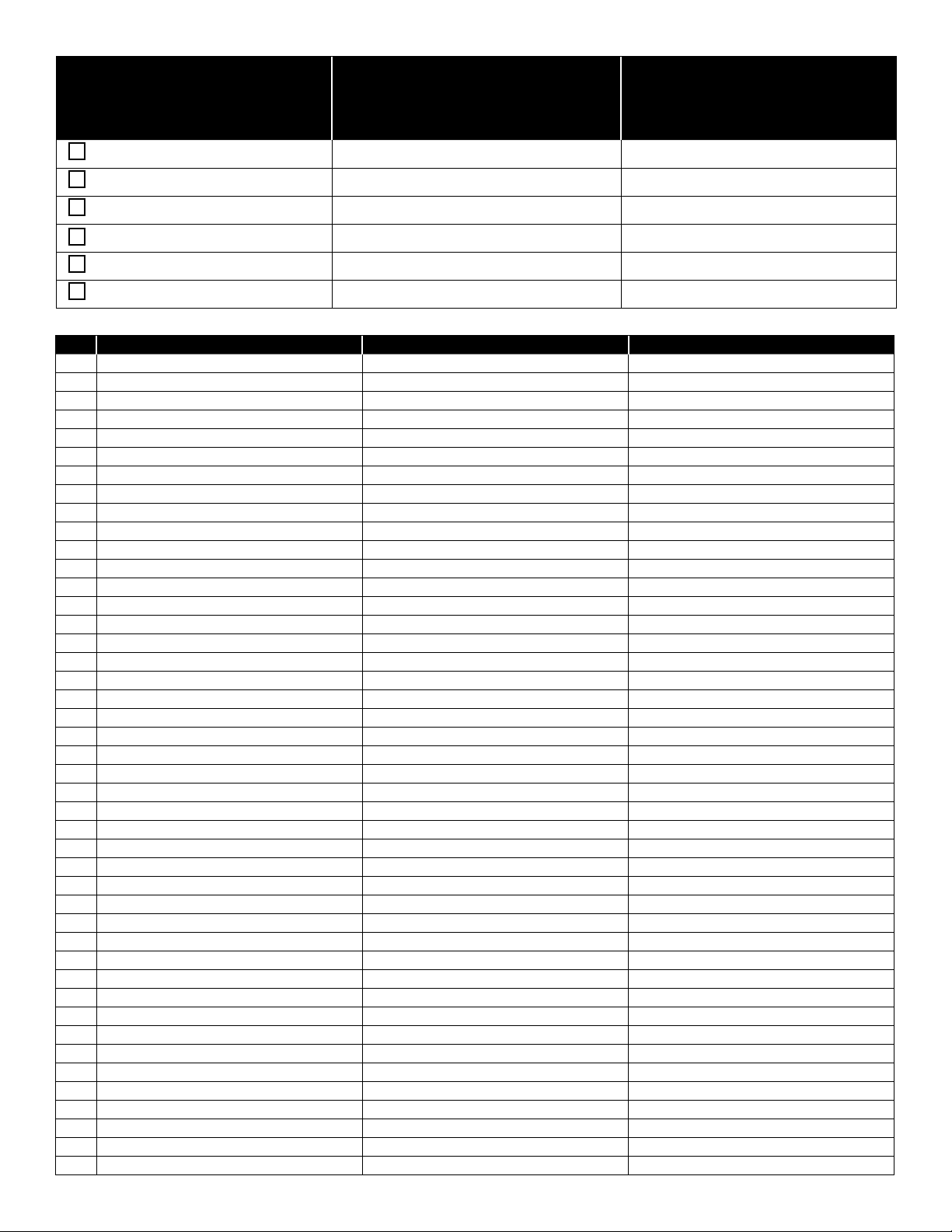
❏ 1. Apply cement very carefully to frame in only those areas
indicated in illustration. Make sure cement does not get
into pivot points on frame.
❏ 2. Join frame parts 1 and 2 sandwiching pivot pins of fork
3 between front of frame.
❏ 3. Press frame together tightly and hold until cement sets.
APPLY CEMENT
AS SHOWN BY
HIGHLIGHTED
AREA
3
E
C
2
3 7541
Page 4

2
SQUARE
PIIN
50
E
APPLY
CEMENT
4
C
8
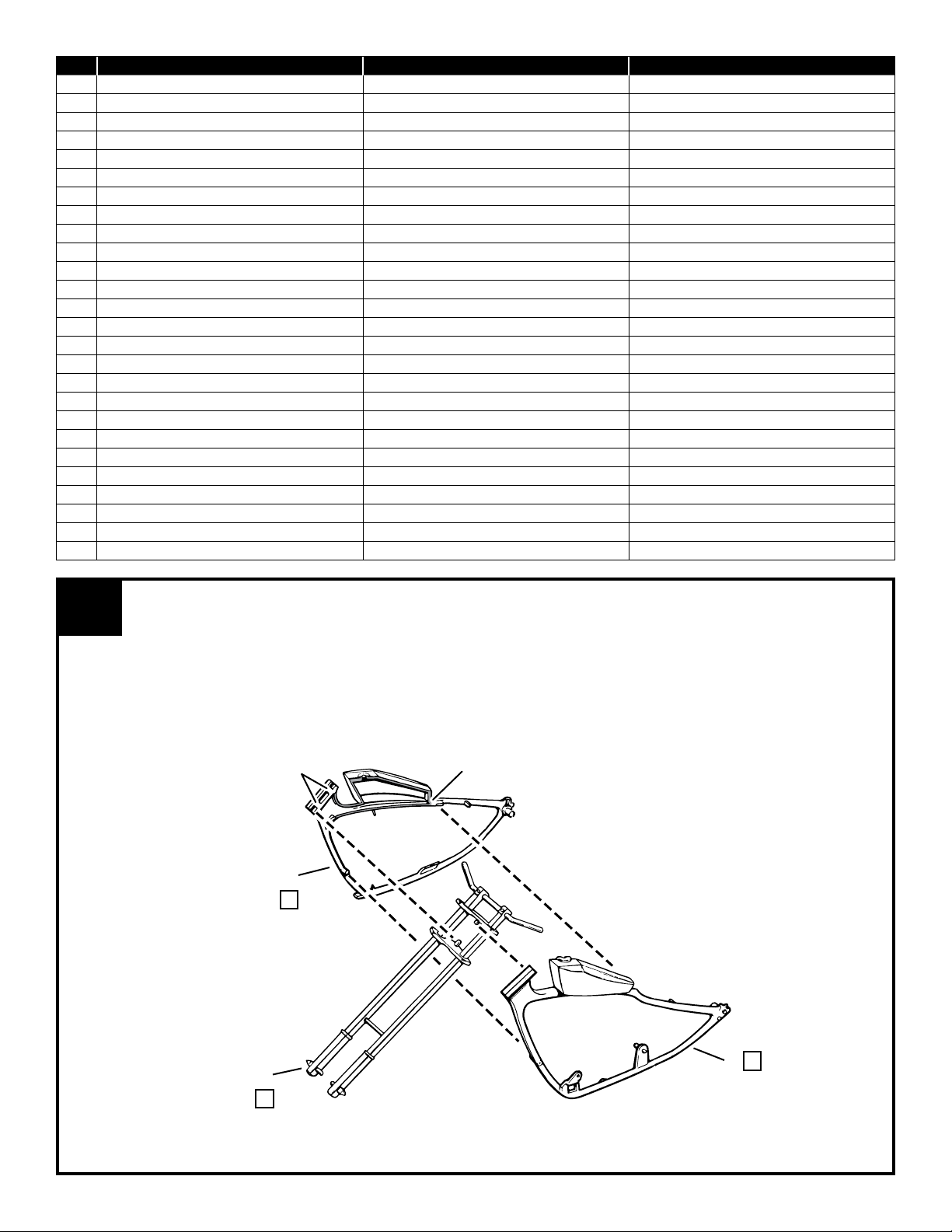
❏ 4. Apply cement to frame as shown and to ends
of support 4. Spread frame and line up square
pin on support into square hole in frame.
❏ 5. Next cement coil halves 7 and 8 together,
then cement tab on coil to support.
❏ 6. Cement pin on regulator 6 into old in support.
❏ 7. Cement support 5 into frame with the topend
B
7
NOTCH
B
PUSH TOP IN
NOTCH AS FAR
AS IT WILL GO
C
5
E
65
6
E
fitting into NOTCH in the top frame.
❏ 8. Cement cap 50 to gas rank and two plugs 65
to rear of frame.
E
65
3
12
"U" NOTCH
10
E
9
H
SQUARE
HOLE
C
13
H
SUPPORT
A
CHAIN ONLY
REAR
AXLE PIN
A
11
E
A
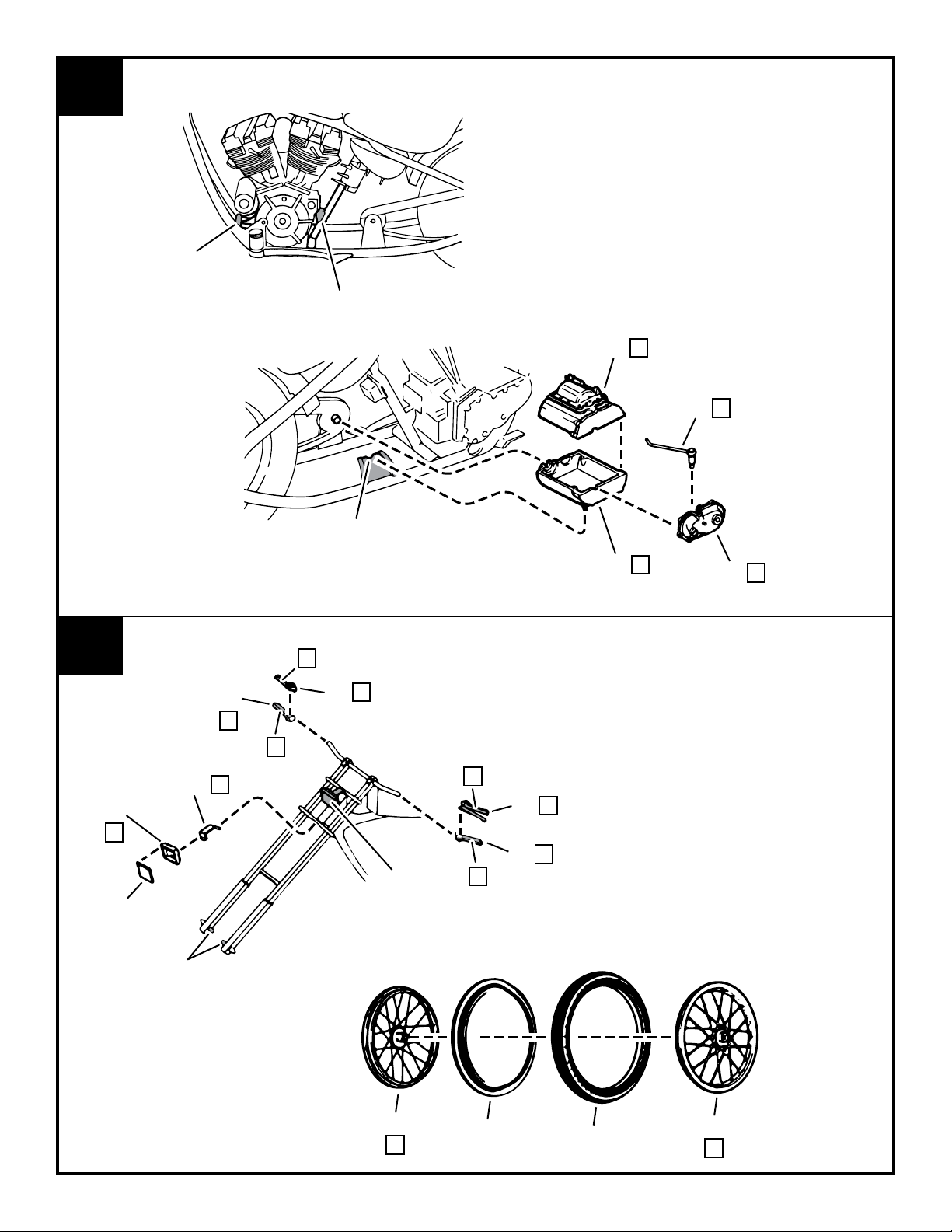
❏ 9. Now cement oil tank halves 9H and
10 tegether, Cut two tubes “A” to
length shown on pattern and press
boeth into ins on bottom of tank.
Cement tank to frame with “U” notch
in tank fitting against support.
❏ 10. Slip (do not cement) large gear on
chain drive 11 over rear axle pin.
❏ 11. Cement small gear on chain drive
onto pin on frame as shown.
❏ 12. Slip (do not cement) bracket 12
onto kick stand 13H. Snap bracket
into square hold in frame and add
cement to back where bracket
touches frame. Make sure that the
kick stand will operate.
❏ 13. Press rear tire and insert together.
❏ 14. Insert wheel half 14H into tire.
❏ 15. Next apply cement to wheel half
15H and press into other side of
tire. Hold wheel halves together
tightly until cement sets.
❏ 16. Spread frame apart slightly and slip
(do not cement) wheel onto rear
axle pins.
14
H
7541 4
REAR
TIRE
REAR
TIRE INSERT
15
H
TUBING PATTERN
TUBING "A" -2 REQ'D
A
Page 5

4
5
33
E
27
E
17
C
37
E
23
E
19
B
34
36
❏ 17. Cement sissy bar 16 into frame with large
B
18
LARGE
NOTCH
CROSS
PIECE
C
16
H
30
H
31
H
34
H
E
E
33
29
35
H
E
28
26
E
20
H
32
24
B
E
notch in bar towards front as shown. Make
sure the sissy bar is on as far as it will go.
❏ 18. Cement fender 17 onto pins on frame and
cross piece on sissy bar.
❏ 19. Next cement seat back into seat.
❏ 20. Now cement assembled seat to fender with
pins on fender fitting into seat.
❏ 21. Crankcase halves 20H and 21H
together.
❏ 22. Cover 22 to side of crankcase.
❏ 23. Oil pump 23 to crankcase.
❏ 24. Generator 24 to housing 25H then
cement to back side of cover 22.
❏ 25. Pushrod plates 26 and 27 on
crankcase with tabs fitting onto
slots.
❏ 26. Cylinder halves 28H, 29H, 30H and
31H together, then cement to top of
crankcase.
❏ 27. Timer 32 onto large pin on side of
cylinder.
❏ 28. Half round pins on ends of four push
rods 33 into holes in covers 34H.
❏ 29. Tabs on covers 34H into slots in top
H
38
of cylinders and fit bottom of push
rods into holes in plates 26 and 27.
❏ 30. Carburetor halves 35 and 36
together.
❏ 31. Large pin on carburetor into hold in
air cleaner 37.
❏ 32. Completes careburetor onto pad
between cylinders.
❏ 33. Two spark plugs 38H into holes in
cylinders at an angle as shown in
illustrations “A”.
D
22
E
21
H
25
H
ILLUSTRATION
"A"
5 7541
ANGLE
AS SHOWN
Page 6
6
SUPPORT
NOTCH
NOTCH IN
FRAME BRAKET
❏ 34. Completed engine assmbly into frame. Two
tabs on crankcase front fit into hole in engine
support. Rib on rear of crancase fits into
notch on center support.
❏ 35. Gear box halves 39H and 40H together.
❏ 36. Pin on housing 41 into hole in gear box.
❏ 37. Lever 42 to housing.
❏ 38. Hold in gear box over pin sticking through
small gear on chain drive, and pin on bottom
of bear box into notch in frame bracket.
H
40
E
42
H
39
41
E
7
45
E
CLEAR
LENS
AXLE
PINS
62
48
H
E
❏ 39. Press tire insert into front tire.
B
H
49
B
B
H
47
H
46
SHOWN IN
PLACE
B
❏ 40. Insert one wheel half 43H into front tire.
❏ 41. Next apply cement to other wheel half
43H and press into other side of tire.
Hold wheel halves together tightly until
cement sets.
❏ 42. Spread bottom of fork apart and fit (do
not cement) axle pins into hles in wheel.
❏ 43. Cement clear lens into headlights 45.
❏ 44. Cement brackets 62 and headlights
together and cement into notches in
fork.
❏ 45. Next cement handlegrip halves 46H
and 47H together and cement to left
handlebar.
❏ 46. Cement grips 48H and 49H and cement
to other handlebar.
43
H
7541 6
TIRE INSERT
FRONT
FRONT
TIRE
43
H
Page 7

8
❏ 47. Exhaust pipe 51H to outlet on cylinder and to side of frame.
❏ 48. Exhaust pipe 52H to cylinder outlet and to top of pipe 51.
❏ 49. Pedal 53 to gear box.
❏ 50. Brake pedal 54 to gear box.
9
52
H
B
PIN FITS LEDGE
IN EXHAUST PIPE
BACK OF DISC
B
GROOVE IN
CYLINDER
OUTLET
53
56
E
E
CYLINDER
OUTLET
H
51
PAD
B
E
54
B
B
❏ 51. Pin on clutch pedal 55 through
hole in arm of clutch 56 and then
through hole in frame bracket.
❏ 52. Clutch to gear box by fitting froove
in disc onto rib on side of gear box.
❏ 53. Drive cover halves 57H and 58H
together.
❏ 54. Drive cover onto pin on crankcase
and frame as shown.
❏ 55. Two foot rests 59 to frame.
59
E
59
E
HOLE IN
FRAME BRACKET
E
B
55
H
58
H
57
7 7541
Page 8

10
61
E
NOTCH
RIBS
60
❏ 56. Cross 61 to notch in sissy bar.
❏ 57. Clear lens into taillight 60H.
❏ 58. Taillights against rib on fender.
H
CLEAR
LENS
F
11
FRONT SPARK
PLUG TO BOTTOM
PIN OF COIL
D
PIN ON SUPPORT
5 TO HANDGRIP 47
(SEE STEPS 2 AND 7)
TIE TUBING TO
FRAME WITH
THREAD OR TAPE
REAR SPARK
PLUG TO TOP
PIN OF COIL
C
Add the spark plug leads and the fuel and brake lines for the final
touch of realism.
Cut the black tubing supplied to the required legnths over the
patterns. Press (do not cement) tubing onto the pins.
Use tweezers to fit the tubing onto pins located in difficult to reach
areas. Now refer to the photos and attach your tubing.
PHOTOS ARE CODED TO INDICATE LOCATIONS OF TUBING
B
C
REAR TUBE ON
OIL TANK TO
INSIDE PIN ON
OIL PUMP
INSIDE
PIN
FRONT TUBE ON
OIL TANK TO
OUTSIDE PIN ON
OIL PUMP
OUTSIDE
PIN
OIL PUMP
GAS TANK
TO PIN ON
CARBURETOR
TUBING PATTERNS
TUBING "B" -1 REQ'D
B
TUBING "C" -2 REQ'D
C
TUBING "D" -1 REQ'D
D
Tom Daniel name, signature and designs used under license. © 2016 Tom Daniel ™. All Rights Reserved.
Le nom, la signature et les designs de Tom Daniel sont utilisés sous licence © 2016 Tom Daniel ™ .Tous Droits Réservés.
El nombre, rma y diseños de Tom Daniel se usan bajo licencia. © 2016 Tom Daniel ™ .Todos Los Derechos Reservados.
7541 8 Revell Inc Elk Grove Village, IL. © 2016
 Loading...