

Page 1
Installation
Instructions
WB28K10553 High Altitude Kit
For Monogram Professional Range and Rangetop Installations
at Elevations of 6,000 Feet or More Above Sea Level
WARNING: This conversion must be
performed by a qualified installer or gas supplier in
accordance with the manufacturer’s instructions and
all codes and requirements of the authority having
jurisdiction. Failure to follow instructions could result
in serious injury or property damage. The qualified
agency performing this work assumes responsibility
for the conversion.
This kit is designed for both LP and Natural Gas range
and rangetop models. Use only the orifices specified.
Additional orifices may be present.
Keep all orifices and parts that are removed for
possible future use.
TOOLS YOU NEEDED FOR CONVERSION
Small Flat-Head Screwdriver
Safety Glasses
1/2” Deepwell
Socket Wrench
1/4” and 7mm Nutdrivers
(2 to 2.4 mm or 3/32” tip size,
60 mm long)
Small Pliers
Philips
Screwdriver
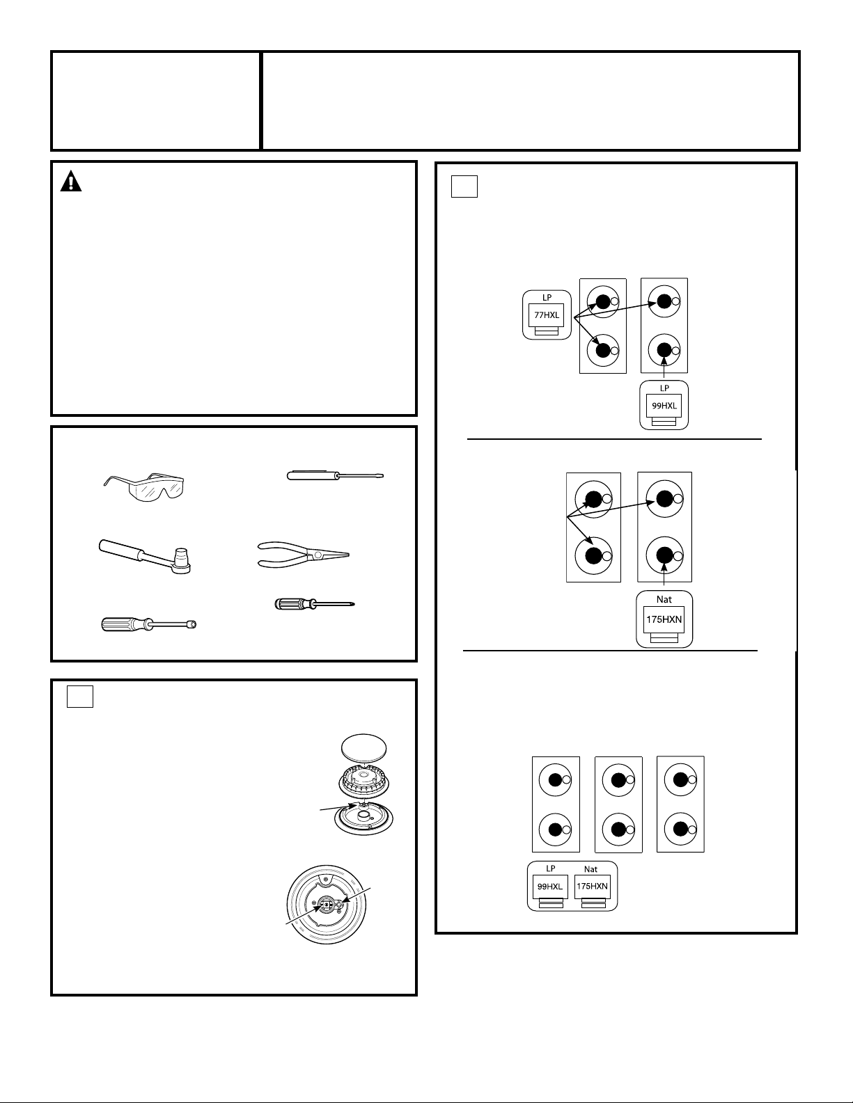
2
CHANGE BURNER ORIFICES
IMPORTANT: Find your model number below. Read
each orifice label to identify and install them in the
exact locations shown.
A.
Replace the main burner orifice on all burners
30” LP Range Model ZDP304L and ZGP304L
as indicated.
B.
Replace the burner heads, caps and top grates
Use 77HXL orifice
on three burners
for LP model
ZDP304L and
ZGP304L.
30” Natural Gas Range Model ZDP304N and ZGP304N
DO NOT
CHANGE THESE
NATURAL GAS
ORIFICES.
Use a 99HXL
orifice for the
right-front
burner.
Use a 175HXN
orifice for the
right-front
burner.
.
1
CHANGE BURNER ORIFICES
INSTALLATION TIP: The orifices for
ranges and rangetops operating on
either gas type—Natural or LP—are
included in this kit. Select and use only
the orifices specified for the type of
gas being used.
A. Remove the burner grates, burner
caps and burner heads.
B. Change only the main burner
orifices. The main orifice is located in
the center of the burner. The simmer
orifice is located higher beside the
center of the burner. Do not change
the simmer orifice.
NOTE: Models equipped with a grill do not require a grill
orifice change.
Spark
Igniter
Main
Orifice
Burner Cap
Burner
Head
Burner Base
Simmer
Orifice
ALL 36” AND 48” RANGE OR RANGETOP MODELS:
ZDP364, ZDP366, ZDP484, ZDP486, ZGP364,
ZGP366, ZGP484, ZGP486, ZGU364, ZGU366,
ZGU484, ZGU486
MAIN
ORIFICES
Use 99HXL or
175HXN orifices
for all burners.
31-10698-3 11-10 GE
Page 2
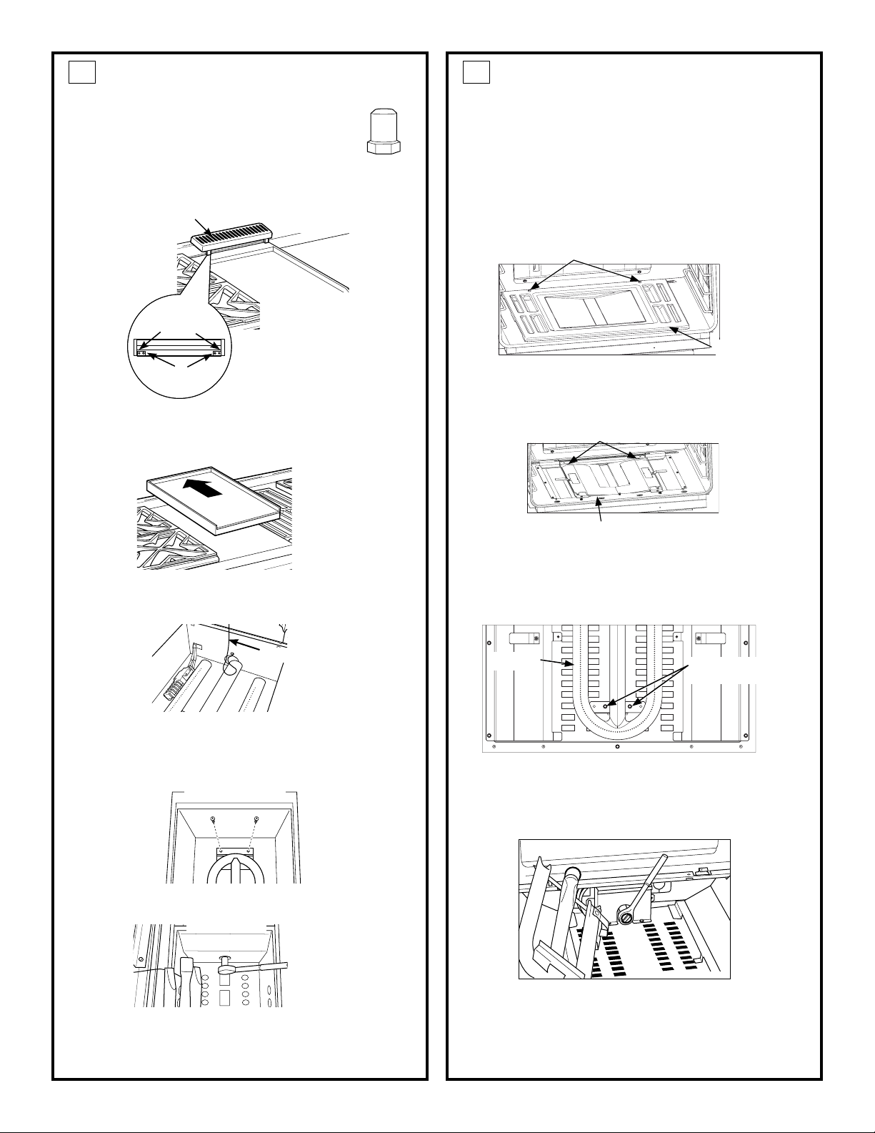
CHANGE GRIDDLE ORIFICE
3
(if present)
Locate the 3/4” long griddle orifice. Select the
proper orifice size for your gas and burner from the
conversion chart.
A. Lift off the griddle flue cover. Remove the 2 inside
clamping screws.
Griddle Flue Cover
NOTE: Remove
the 2 screws
Leveling Screws
Clamping Screws
positioned on
the inside only.
Do not remove
the outermost
screws—they
are for leveling.
B. Lift out the cast-iron grease trough. Slide the
griddle toward the rear and out of the hold-down
tabs along the bottom.
4A
CHANGE MAIN BAKE BURNER
ORIFICE (if present)
Locate the 3/4” long bake burner orifice.
Select the proper orifice size for your gas and burner from
the conversion chart.
A. Remove the oven door and set aside in a safe
location.
B. Remove the 2 oven bottom hold-down screws
from the rear of the cover.
Hold-Down Screws
Oven
Bottom
C. Slide the oven bottom forward and set aside.
D. Remove the burner diffuser screw.
Clips
C. Carefully lift and hold the griddle while pulling
additional length of the capillary from the entry
hole. Stand the griddle on end in the grease sump.
Capillary
D. Remove the 2 hold-down screws at the rear of the
burner.
Pull the burner straight back toward the rear and
out of the gas inlet.
Back of Range
E. Use a 1/2” deepwell socket to remove and replace
the orifice.
Front of Range
Diffuser screw
E. Lift the front of the burner diffuser up slightly and
slide it forward to disengage the clips at the rear.
Set the burner diffuser aside.
F. Remove the 2 burner retention screws.
Burner
Lift the front of the burner up slightly and slide for-
G.
Burner retention
screws
ward setting aside (careful not to damage the igniter.)
H. Use a 1/2” deepwell socket to remove and replace
the orifice.
Reverse these steps to reassemble the griddle.
Push excess capillary back into the entry hole.
Place the unused orifice in the holder for possible
future use.
I. Reverse these steps to reassemble the griddle.
Push excess capillary back into the entry hole.
Place the unused orifice in the holder for possible
future use.
2
Page 3

4B
CHANGE COMPANION BAKE BURNER
ORIFICE (if present)
Locate the 3/4” long bake burner orifice.
Select the proper orifice size for your gas and burner
from the conversion chart.
A. Remove the oven
door and set
aside in a safe
location.
B. Remove the 2
oven bottom
hold-down
screws from the
rear of the cover.
C. Slide the oven bottom forward and set asside.
D. Remove the burner diffuser screw.
E. Lift the front of the
burner diffuser up
slightly and slide it
forward to disengage the clips at
the rear. Set the
burner diffuser
aside.
F. Remove the 3
burner retension screws
(1 in front and 2 at the
rear)
G. Lift the front of the burner
up slightly and slide
leftward to remove.
H. Use a 1/2” deepwell
socket to remove and
replace the orifice.
I. Reverse these steps to
reassemble the griddle.
Push excess capillary
back into the entry hole.
Place the unused orifice
in the holder for possible future use.
Hold-Down
Screws
Oven
Bottom
Clips
Diffuser Screw
Burner
Retension
Screws
5
ADJUST BURNER FLAMES
Normally, burners do not need further adjustment.
Make adjustments only when necessary.
A. Turn on the gas. Plug in electrical cord.
B. Turn all burners on highest setting and check the
flames. They should be blue in color. When using
LP gas, the flames may have some yellow tipping
at the ends of the flame. Foreign particles in the
gas line may cause an orange flame at first, but
this will soon disappear.
C. Turn the burner knob to “LO” while observing the
flame.
Adjust the setting of the upper row of flames using
the valve bypass screw as follows:
Adjustments must be made with two other
burners in operation on a medium setting. This
prevents the upper row of flames from being set
too low, resulting in the flame being extinguished
when other burners are turned on.
D. To adjust the flame, remove the knobs. Insert a
small flat-blade screwdriver into the hole in the
center of the valve stem to engage screw.
• If the flames are too small
or flutter, turn the screw
counterclockwise.
• If the flames are too large,
turn the screw clockwise.
E. Make the adjustment by slowly turning the screw
until flame appearance is correct.
Once the conversion is complete and checked, fill out the
conversion label and affix the label near the rating label.
For ranges, place the label beneath the control panel. For
rangetops, place the label on the bottom of the unit.
3
Page 4

BURNER OUTPUT RATINGS: BTU/HR
NG (Natural) Gas, 5” W.C.P.
MODEL BURNER
ZDP48,
ZGP48,
ZGU48
ZDP36,
ZGP36,
ZGU36
ZDP304
ZGP304
ZDP304
ZGP304
ALL GRILL 15,000
ALL GRIDDLE 18,000
ZGP48,
ZGP36
ZGP30 BAKE MAIN 20,500
ZGP48 BAKE COMPANION 9,000
ZGP304,
ZGP36
ZGP48
ZGP48 BROIL COMPANION 9,000
ALL SURF. Main 16,800
BURNERS Simmer 1,200
RF BURNER
Simmer 1,200
RR, LR, LF
Simmer
BAKE MAIN 20,500
BROIL MAIN 12,500
Main 16,800
Main
BTU
RATE
8,800
1,200
ORIFICE
SIZE
0.075”
(1.90mm)
0.002”
(0.51mm)
0.075”
(1.90mm)
0.002”
(0.51mm)
0.050”
(1.26mm)
0.002”
(0.51mm)
0.0689”
(1.75mm)
0.067”
(1.70mm)
0.0807”
(2.05mm)
0.0807”
(2.05mm)
0.0492”
(1.25mm)
0.063”
(1.60mm)
0.052”
(1.32mm)
ID
175HXN
51SL
175HXN
51SN
126HXN
51SN
0.069
0.067
0.081
0.081
0.049
160
132
LP (Propane) Gas, 10” W.C.P.
MODEL BURNER
ZDP48,
ZGP48,
ZGU48
ZDP36,
ZGP36,
ZGU36
ZDP304
ZGP304
ZDP304
ZGP304
ALL GRILL 14,000
ALL GRIDDLE 16,000
ZGP48,
ZGP36
ZGP30 BAKE MAIN 20,000
ZGP48 BAKE COMPANION 9,000
ZGP304,
ZGP36
ZGP48
ZGP48 BROIL COMPANION 9,000
ALL SURF. Main 13,800
BURNERS Simmer 1,200
RF BURNER
Simmer 1,200
RR, LR, LF
Simmer
BAKE MAIN 20,000
BROIL MAIN 11,500
Main 13,800
Main
BTU
RATE
7,900
1,200
ORIFICE
SIZE
0.043”
(1.08mm)
0.013”
(0.34mm)
0.043”
(1.08mm)
0.013”
(0.34mm)
0.033”
(0.84mm)
0.013”
(0.34mm)
0.047”
(1.19mm)
0.047”
(1.19mm)
0.0512”
(1.45mm)
0.0512”
(1.45mm)
0.0354”
(0.90mm)
0.041”
(1.04mm)
0.0360”
(0.91mm)
ID
99HXL
34SL
99HXL
34SL
77HXL
34SL
0.047
0.042
0.051
0.051
0.035
104
91
4
 Loading...