

Page 1
Installation
I str cti n
Professional
Outdoor Grills and
Cooktop
Tables de cuisson et barbecues
de plein air professionnels
Instructions d'installation
La section ffan_aise commence _ la page 23
Parrillas y estuf@ profesionales
para el @irelibre
Instrucciones de instalaci6n
La secci6n en espa_ol empieza en la p(_gina 45
C
I31-107021
11-08JR
JS
Page 2
Installation Instructions
BEFORE YOU BEGIN
Read these instructions completely and carefully.
•IMPORTANT- savetheseinstructionsfor
local inspector's use.
• IMPORTANT-Observeallgoverning
codes and ordinances.
• Note to Installer- Be sure to leave these
instructions with the Consumer.
• Note to Consumer - Keep these instructions
with your Owner's Manual for future reference.
If you have questions concerning the installation of
this product, call the GEAnswer Center ®Consumer
Information Service at 800.626.2000, 8 a.m. to
10 p.m.EST,Monday through Friday,and 8 a.m.
to 7 p.m.EST,Saturday.
If you received a damaged grill or cooktop, you
should contact your dealer.
Installation of this outdoor grill or cooktop requires
basic mechanical skills. Proper installation is the
responsibility of the installer.
For Monogram local service in your area,
call1.800.444.1845.
For Monogram service in Canada,
call 1.800.561.3344.
For Monogram Parts and Accessories,
call 1.800.626.2002.
FOR YOUR SAFETY: Donotusethe
grillor cooktop ina space where gasolineorother
liquidshavingflammable vapors are storedorused.
The installation must conform to local codes or, in
the absence of local codes, with either the National
Fuel Gas Code, ANSI Z223.1/NFPA 54, National Gas
and propane Installation Code.
- WARNING:
• For outdoor use only. Use this outdoor grill or
cooktop only in the manner intended by the
manufacturer.
• This outdoor cooking gas appliance is not
intended to be installed in or on recreational
vehicles and/or boats.
Do not use the grill in on explosive atmosphere.
Keep the grill away from areas where gasoline or
other flammable liquids and vapors are stored or
being used.
Observe proper clearances to combustible
materials at all times.
Do not use a rusty or damaged LP tank.
Never substitute gases (natural for LPor LP for
natural). These grills ore factory-set for LP or
natural gas. Order the model for the installation
situation.
When storing the grill indoors, disconnect the
LP tank. Store the tank outdoors in a well
ventilated urea.
• Do not store additional LP tanks in or near the
gas grill.
Follow the guidelines on the LPtank for proper
storage, transport and handling.
IF YOU SMELL GAS:
• Shut off gas to appliance.
• Extinguish any open flame.
• Open lid.
If odor continues, keep away from the appliance
and immediately call your gas supplier or fire
department.
BEFORE LIGHTING:
1. Read instructions before lighting.
2. Open lid during lighting.
3. If ignition does not occur in 5 seconds, turn the
burner control(s) to OFF, wait 5 minutes and
repeat the lighting.
Page 3
Installation Instructions
FOR OUTDOOR USEONLY
IMPROPER INSTALLATION, ADJUSTMENT,
ALTERATION, SERVICE OR MAINTENANCE CAN
CAUSE PROPERTY DAMAGE, INJURY OR DEATH.
READ THIS MANUAL THOROUGHLY BEFORE
INSTALLATION, USE OR SERVICING THIS
EQUIPMENT.
CALIFORNIA
PROPOSITION 65
WARNING: The burning of gas
cooking fuel generates some by-products, which
are on the list of substances, which are known bg
the State of California to cause cancer or
reproductive harm. California law requires
businesses to warn customers of potential
exposure to such substances. To minimize
exposure to the substances, always operate this
unit according to the Use and Care instructions
provided with this unit. Be certain to provide
adequate ventilation when cooking. California
Proposition 65 lists "Silica, crystalline" which is used
in one of the components of the IR burner, as an
agent known to the state of California to cause
cancer.
In Massachusetts: All gas products must be
installed using a "Massachusetts" licensed plumber
or gasfitter. A "T" handle type manual gas valve
must be installed in the gas supplg line to this
appliance. This applies to permanentlg installed
natural gas and propane installations. This does
not applg to propane portable installations using a
20-pound tank (not included) plus regulator and
hose assemblg, which is supplied with propane
gas grills.
INSECT WARNING!
Spiders and insects can nest in the burners of this
and ang other grill and cause the gas to flow from
the front of the burner. This is a very dangerous
condition which can cause fire to occur behind the
valve panel, thereb U damaging the grill and making
it unsafe to operate. Inspect the grill twice a gear or
immediatelg if ang sgmptoms appear.
CODE COMPLIANCE
Test in accordance with ANSI Z21.58 latest edition
standard for outdoor cooking gas appliances.
This grill is for outdoor use onlg. Check local
building codes for the proper method of installation.
In the absence of local codes, this unit should be
installed in accordance with the National Fuel Gas
Code No. Z223 latest edition and the National
Electrical Code ANSI/NFPA no. 70, latest edition.
CAUTION: Alloutdoorgrillsare
extremely heavy. Two people are required to lift
and place a built-in grill into an enclosure. At least
two people are also required to remove a grill on
cart from the skid.
Page 4
Design Information
CONTENTS
Design Information
Models Available ......................................................................a
Product Dimensions and Clearances ......................5-7
Accessories ................................................................................8
Accessory Product Dimensions ........................................8
Installation Preparation
Advance Planning ................................................................9
Choosing the Location ........................................................9
Electrical Supply Requirements ....................................10
Gas Supply Requirements ..............................................10
Outdoor Grill, Cooktop and
Accessory Cutout Dimensions ......................................11
Tools Required ......................................................................12
Materials Required ..............................................................12
Parts Provided ......................................................................12
Remove Packaging from Cart Models ..............1:3,14
Remove Packaging from Built-in Models ..................15
Installation Instructions
LP Tank Tie-Down ................................................................16
Tank Drawer with LPTank Retainer Loop ................16
LP Gas Grill Connections
to a Grill or Cooktop ..................................................16, 17
Natural Gas Grill Connections ......................................17
Leak Testing ..........................................................................18
Make Electrical Connections ..........................................19
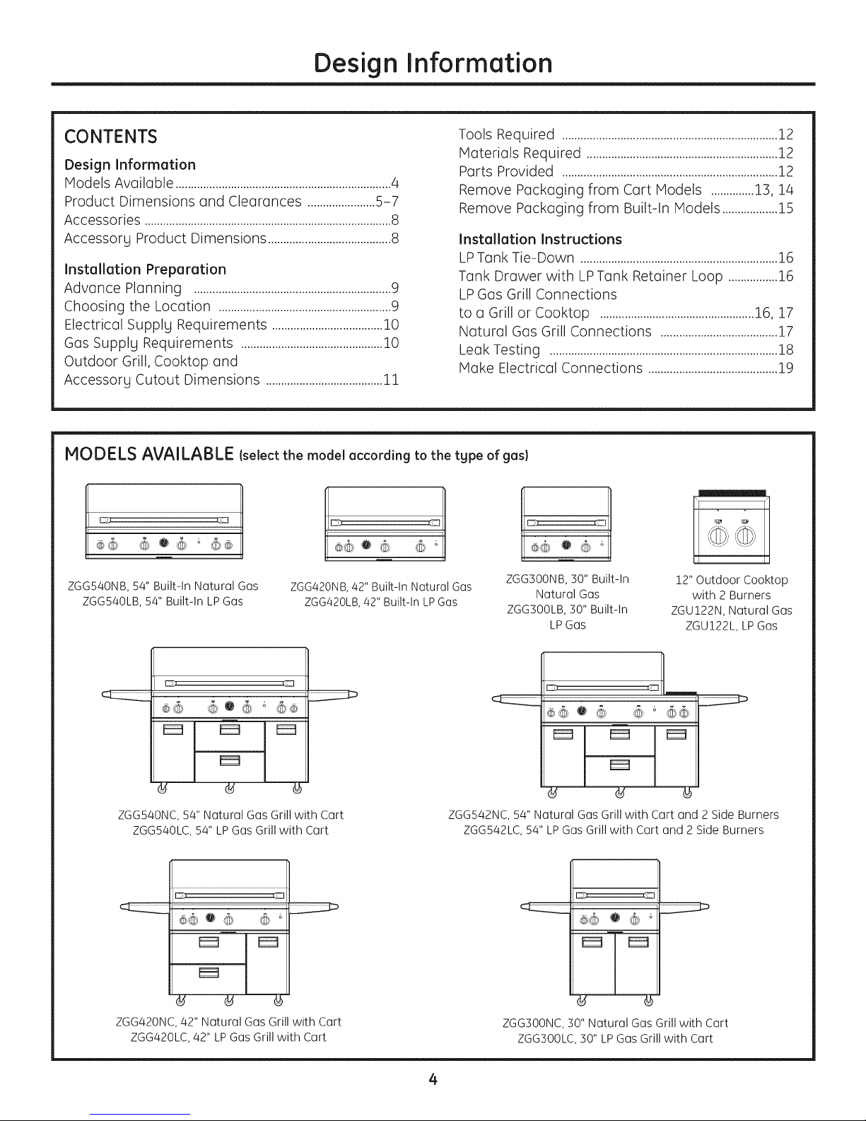
MODELS AVAILABLE (select the model according to the tgpe of gas)
<&o&, 6 _
ZGG540NB, 54" Built-In Natural Gas
ZGG540LB,54" Built-In LPGas
E_ CZ3
d
ZGG540NC,54" Natural Gas Grill with Cart
ZGG540LC,54" LPGas Grill with Cart
®@ O (®
ZGGa20NB, 42" Built-In Natural Gas
ZGGa20LB, 42" Built-In LP Gas
G'®
ZGG300NB, 30" Built-In
Natural Gas
ZGG300LB, 30" Built-In
LPGas
12" Outdoor Cooktop
with 2 Burners
ZGU!22N, Natural Gas
ZGU!22L, LPGas
l
d
ZGG542NC,54" Natural Gas Grill with Cart and 2 Side Burners
ZGG542LC, 54" LPGas Grill with Cart and 2 Side Burners
d
ZGGa20NC, 42" Natural Gas Grill with Cart
ZGGa20LC, 42" LP Gas Grill with Cart
ZGG300NC,30" Natural Gas Grill with Cart
ZGG300LC,30" LPGas Grill with Cart
4
Page 5
Design Information
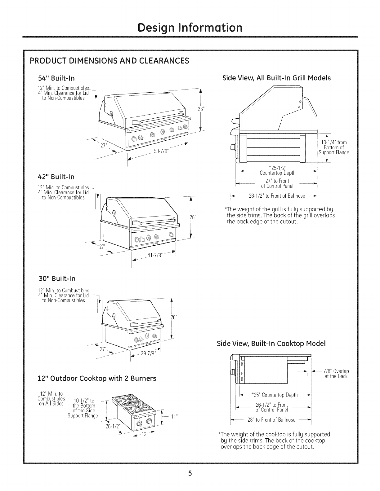
PRODUCT DIMENSIONS AND CLEARANCES
54" Built-In
12"Min.to Combustibles_
4" Min. Clearancefor Lid -1
to Non-Combustibles
42" Built-In
12"Min.to Combustibles....
4" Min. Clearancefor Lid ._
\,.........
I v
............. _---_41#/8 ........_"
Side View, All Built-ln Grill Models
i A
fl 1¢1/4" from
I I Bottomof
I I iiSupportFlange
U ........................:_............._.......
_25-1/2"
CountertopDepth
i i 27"to Front
' of ControlPanel
i
28-1/2"to Frontof Bullnose
*The weight of the grill isfully supported by
the sidetrims. Theback of the grill overlaps
6"
the back edge of the cutout.
30" Built-In
12"Min. to Combustibles
4" Min.Clearancefor Lid - ,
to Non-Combustibles _ ..... ..............
.................. 26"
i ..... !
297/8
I
::1.2"Outdoor Cooktop with 2 Burners
12"Min.to
Combustibles
onAll Sides
10-1/2"to ...._---_
the Bottom ::
of theSide ................._: J _4//_--_---
SupportFlange {__ I,. _ T
.........J_ -13''_1
Side View, Built-In Cooktop Model
i _ ...............i i_..............atthe Back
-i _ J 7/8" Overlap
B
_ .........25" Countertop Depth _:
11"
i-4 28"to Frontof Bullnose ,'4
i
26-1/2"to Front
ofControlPanel
*The weight of the cooktop is fully supported
by the side trims. The back of the cooktop
overlaps the back edge of the cutout.
Page 6
Design Information
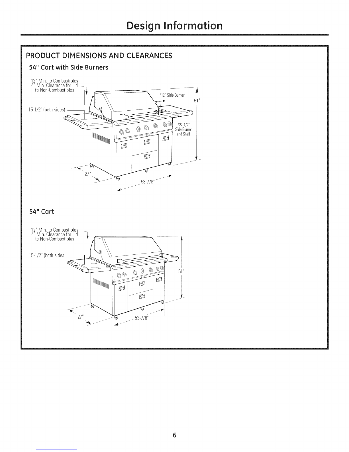
PRODUCT DIMENSIONS AND CLEARANCES
54" Cart with Side Burners
12"Min. to Combustibles
4" Min.Clearancefor Lid
to Non-Combustibles -i_
15-1/2"(bothsides)
54" Cart
12"Min. to Combustibles -
4" Min. Clearancefor Lid ,.
to Non-Combustibles
15-1/2"(bothsides)--
53-7/8"
_ _27-1/2"
SideBurner
andShelf
51"
__- 53-7/8"
..
_-
Page 7
Design Information
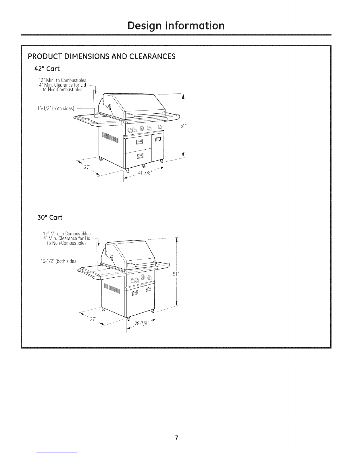
PRODUCT DIMENSIONS AND CLEARANCES
42" Cart
12"Min. to Combustibles
4" Min. Clearancefor Lid --_
to Non-Combustibles I_'
15-1/2"(bothsides_
S
//41-7/8"
51 "
30" Cart
12"Min. to Combustibles
4" Min. Clearancefor Lid _ ,
to Non-Combustibles :_
15-1/2"(bothsides)--
51 "
°
7
Page 8

ACCESSORIES
Design Information
ZX18DS, 18" 2-Drawer Storage
ZX27AD, 27" Access Doors
ACCESSORY PRODUCT DIMENSIONS
22-5/8"
;_ 18-1/8"_
2G"
ZX18TC, 18" Trash Bin
20"
27" •........................................_-
J
Page 9

Installation Preparation
ADVANCE PLANNING
Built-In Monogram Outdoor Grills (Ire designed for
easg installation into a masonrg, non-combustible
enclosure. The grill drops into he opening and hangs
from its side flanges.
• A deck is not required for support from the bottom.
The cutout must be completely covered with
non-combustible material such as stone, brick,
ceramic tile, concrete board, etc. The counter surface
and edges must be flat and level.
Clearances:
• A 4" minimum
cleorance is
required behind
the grill to allow
the hood to open.
Clearances to Combustible Materials:
• Allow at least a 12" clearance at the back of the grill
when the exhaust is directed to a window or a
surface that is difficult to clean.
Allow 12" minimum cle(_rance on both sides and the
back of the grill to adjacent vertical combustible
construction.
These gas grills cannot be used below ang tgpe of
overhead construction.
Accessories:
• ZX27AD Access Doors mag be installed directlg
below a grill.
ZX18DS Storage Drawers CANNOT be installed
directlg below a grill or cooktop.
ZX18TCTrash Bin CANNOT be installed directlg below
a grill or cooktop.
Security:
Cart models (Ire equipped with (In anti-theft,
stationarg-mount securitg loop. This loop allows
gou to secure the grill to (_structure. See page 19.
Cooktop Installation:
Both an LPor Natural gas cooktop con be installed
in combinotion with a grill. The cooktop con be
connected to the same LP tank as the grill.
The cooktop con also be installed alone and be
supplied by a separate LPtonk. In this cose, you
must order (_regulator hose assembly. Order
WB21X10156 regulator hose assembly for (_20-lb.
LPtank connection.
4" Min.
LidClearance
CHOOSING THE LOCATION
These outdoor grills (Ire designed for outdoor use
only. Do not Iocote the grill in a building, garage
or other enclosed or semi-enclosed area.
• Ensure that fresh air ventilation is adequate.
NEVERUSETHEGRILLIN WINDY CONDITIONS.Windhitting
the grillwhile in use,espedallywinds blowinginto oracrossthis
hoodgap,can causepoorperformanceandin somecasescan
causethecontrolpanelto get hot enoughtocauseburns.
Steadyor gustywindscanpreventthenormalexhaustofhot
gases.Locateyourgrillawayfromprevailingwindsandavoid
grilling inwindy conditions.
• Locate the grill where prevailing winds will blow
into the front of the control panel.
The minimum clear(races to combustibles must
be maintained at all times.
• Do not install an outdoor grill below overhead
unprotected combustible construction.
The location must be level and stable.
9
Page 10

Installation Preparation
ELECTRICAL SUPPLY REQUIREMENTS
A 120-volt, 60Hz, 1S-amp power supplg is required.
An individual properly grounded branch circuit or
circuit breaker is recommended. Install a properly
grounded 3-prong electrical receptacle at the rear
and below the cutout. Electrical must be located
within reach of the 6-ft. power cord.
GROUNDING THE OUTDOOR COOKING
CENTER AND 2-BURNER COOKTOP
IMPORTANT: PLEASEREAD CAREFULLY.FOR
PERSONALSAFETY,THIS APPLIANCE MUST BE
PROPERLYGROUNDED.
The power cord of this appliance is equipped with a
3-prong (grounding) plug which mates with a standard
3-prong (grounding) wall receptacle to minimize the
possibilitg of electric shock hazard from this appliance.
Have the wall outlet and circuit checked by a qualified
electrician to make sure the outlet is properlg
grounded. Where a standard 2-prong wall outlet is
encountered, it is gout personal responsibilitg and
obligation to have it replaced with a properlg
grounded 3-prong wall outlet.
• DO NOT,UNDERANY CIRCUMSTANCES,
CUTOR REMOVETHETHIRD (GROUND)
PRONGFROMTHE POWERCORD.
DO NOT USEAN ADAPTERPLUGTO
CONNECTTHE OUTDOORCOOKING
CENTERTOA 2-PRONG OUTLET.
DO NOT USEAN EXTENSIONCORD
WITH THISAPPLIANCE.
• DO NOT PLACETHE UNITIN STANDING
WATEROR ALLOW THE POWERCORD
TO BE IMMERSED.
THIS PRODUCT ISRECOMMENDED TO
BECONNECTED TO A POWER
SOURCEWITH GROUND FAULT
CIRCUIT INTERRUPT(GFCI)
PROTECTIONWHEN INSTALLED IN AN
OUTDOOR LOCATION. FOLLOW
LOCAL CODES.
If gou are uncertain about the GFCIprotection on
the power source to which gou are connecting this
appliance, please contact a professional electrician
for verification.
GAS SUPPLY REQUIREMENTS
These grills are factorg-set for either LP or natural
gas operation.
Do not attempt to operate the cooking center on a
different gas type than for what the grill orifices and
regulator are set. Check the rating plate to be sure
the gas supply matches the cooking product. Fuel
type conversion requires a conversion kit. Contact
your dealer or call 1.800.626.2002 to order.
GAS TYPE CONNECTIONS
AND CONVERSIONS
• WB28X10116 - LP to Natural Gas Operation
Conversion Kit. This kit is for all grill models
and 2-burner cooktops. Order this kit from
your Monogram supplier.
WB28X10117 - Natural to LP Gas Operation
Conversion Kit. This kit is for all grill models
and 2-burner cooktops. Order this kit from
your Monogram supplier.
• WB28X10118 - LP Portable/Stationarg
Conversion Kit. To change the connection from
LP portable (20# tank) to whole house stationarg
tank or stationarg tank to portable. Order this kit
from gour Monogram supplier.
• WB28X10119 - High Altitude Conversion Kit.
For operation above 2,000 feet. Order this kit
from gour Monogram supplier.
COOKTOP AND OUTDOOR COOKING
CENTER COMBINATION INSTALLATION
• Natural gas models are designed to operate
at 4" water column pressure. For proper
operation, the pressure of the natural gas
supplied to the regulator must be between
5" and 14" water column.
LP models are designed to operate at 11" water
column pressure. For proper operation, the
pressure of the LP gas supplied to the regulator
must be between 12" and 14" water column.
Install a manual shut-off valve in the gas line
(not provided), in an easilg accessible location.
Make sure the homeowner knows where and
how to shut off the gas supplg to the grills.
10
Page 11

Installation Preparation
OUTDOOR GRILL, COOKTOP AND ACCESSORY CUTOUT DIMENSIONS
12"Min.
28-3/4"for30"Models
40-3/4"for42"Models
52-3/4"for54"Models
Separation
BetweenCutouts
11-7/8"
andElectricalLocations
•24-1/2"
24-1/2"
Grill Cutout
36"
Min.
AccessDoors
ZX27AD
24-1/8"
18-1/4"
Gas and Electrical Locations
6AS LOCATION:
Cuta3-1/2"dia.holefor
themanifoldconnection
asshownfor LPtank
orstationarygasline
connections.
ELECTRICALLOCATION:
Cuta1"dia.hole
atthebackleftside
__i{]/2, ' Dia Hole
rStationary
GasLine
3-1/2"Dia.Hole
forLPTankHose
ofthecutout.
• Ifthe countertop has an overhang, it must be notched or
cut backflush with the front face of the cabinet below.This
will allow the grill or sideburner to fit flush at the front.
ZGU122 10-7/8" ZX18TC
TrashBin
2-Drawer
Storage
ZX18DS
24/4" min.
*Note: When installing more than one accessory below the countertop, align the
accessories across the bottom by adjusting the dimension above the floor.The
cutouts must be offset depending on the product overlap below the cutout.
Overlap for ZX27ADis 7/8", for ZX!8DS is !-!/4" and for ZX!8TC is !-3/!6".
24"
• The grill and outdoor cooktop drops into the opening and
hangs from the sideflanges. Adeck isnot required for
support on the bottom.
The construction must be leveland stable and capable
of supporting up to 400 Ibs.
The opening for the cooktop must be 24-!/2" deep from
the front of the countertop. Cut a !" dia.hole below the
cooktop for the drain hose.
Cut a 1"dia. holeat the back left side of the cutout
for the grill's electrical connection.
A 120 volt outlet must be located within reach of the grill's
6' power cord.Thetransformer bracket must be mounted
within 3-1/2 feet of the outdoor grill.
Haintain 12"separation between cutouts for anoutdoor
grill andan outdoor cooktop installation.
CountertopNotchDetail
5/8" for Grills
9/16"for OutdoorCooktop
Rotisserie
Connection
Thegrill rotisserieconnectionis ontheleft sidenear
the front.Installationinto a 24-1/2"front-to-back
openingallowsaccesstotherotisserieoutlet.
11
Page 12

Installation Preparation
TOOLS REgUIRED
SaberSaw
MeasuringTape
Carpenter'sSquare
SafetyGlasses
Phillips#2Screwdriver
Level
Drilland
AppropriateBits
AdjustableWrench
1/4"DriverorWrench
Flat-BladeScrewdriver
(3/32"blade)
PARTS PROVIDED
Grill Cover
RotisserieSpitForks
9VBattery(installed
onsomemodels)
SmokerBox
(onsomemodels)
RotisserieMotor andConnector
DripPan
BracketwithTransformerand
BatteryCompartment(only
on built-inmodels)
Pliers ApplianceDolly
,/
Utility Knife PipeWrench
MATERIALS REQUIRED (not provided)
PipeJoint Sealant
(approvedtype and
resistantto LPor
naturalgas)
Use stainless steel orflexible metal gas line to reachthe
built-in installation location or cart model location (if natural
or whole-house LP).Do not use vinyl hose.
PipeFittings ManualShut-Off
Valve
CuttingBoard
ionsomemodels)
RotisserieSpitRod
ZGU122 COOKTOP PARTS
LP MODELS
See product to determine parts used.
3/8" FlareTeeandTwo
3/8" x3/8" FlareHoses
(onmodelssoequipped)
12
Page 13

Installation Preparation
REMOVE PACKAGING FROM CART MODELS
1. Cut the banding. Use o box cutter or utilitg knife to
score and cut the carton along the base (or remove
the staples with a staple remover or a screwdriver).
2. Lift the carton straight up and off of the grill.
jCut the banding
with tin snips.
t
L
Score and cut.
3. Remove all outside packing materials.
6. Open the lid. Cut plastic ties and bands.
7. The right-side shelf must be removed when using
an appliance dollLI to lift the grill off the skid.
A. On the right side of the grill, remove the screw
from the back side of the shelf.
Parts
Package
Grill Grates
Parts
Package
4. Remove the parts packages on each side at the bottom.
5. Remove the screws from the hold-down board on the
right side of the skid to allow the appliance dollLI to
slip under the wheels.
NOTE: When using an
appliance dollLI, the
grill must be handled
and removed from the
right side. The right-
side wheels do not
rotate.
H01d-D0wn
Board
B. Slide the shelf out of the holding pin at the front
end of the bracket.
Holding Pin
(;;S
(2;2;-2
13
Page 14

Installation Preparation
REMOVE PACKAGING FROM CART MODELS Icont.)
8. Position the blade of the dollg next to the right
side of the grill. Tilt the grill back and awag to
allow blade to slip under the wheels.
NOTE: The wheels must rest on the blade
of the appliance dollg.
Securethe appliance --
dolly belt aroundthe
grill aboveor below
the controls to avoid
damageto the knobs.
9. Tilt and lift with the appliance dolly to remove the
skid from below the grill.
10. Roll the grill into operating position. Reinstall the
shelf on the right side.
11. Remove the tie holding the sear burner (on
some models). Lift the wire mesh cover on the
sear burner and remove packaging. Carefully,
replace the wire mesh cover. The wire mesh
must be wrapped around the vertical side
flanges.
Wheels must be
positioned ONthe
blade of the appliance dolly.
14
Page 15

Installation Preparation
REMOVE PACKAGING FROM BUILT-IN MODELS
1. Cut the banding. Use o box cutter or utilitg knife
to score and cut the carton along the base (or remove
the staples with a staple remover or a screwdriver).
2. Lift the carton straight up and off of the grill.
Cutthe banding
with tin snips.
-- Scoreandcut.
3. Remove all outside packing materials.
4. Remove the screws from the hold-down boards on
the skid. This will allow better access to the ends
when lifting the grill off the skid.
6. Close the lid. Cut the plastic tie holding the
wires against the left side. Let the batterg
and transformer wires hang loose along the
back side.
I
Cuttie on the rearverticalsupport.
,
Lift the grill off the skid and slide it into the
prepared countertop opening.
8.
Remove the tie holding the sear burner (on
some models). Lift the wire mesh cover on the
sear burner and remove packaging. Carefullg,
replace the wire mesh cover. The wire mesh
must be wrapped around the vertical side
flanges of the burner.
Boards
5. Open the lid. Cut plastic ties and bands. Remove
the parts package. Remove the grill grates and
packaging.
15
Page 16

installation
LP TANK TIE-DOWN {for built-in island installations}
Outdoor cooking applicances require an integral
means of limiting the movement of the LPgas cylinder.
For built-in appliances which require the use of a
remote LPgas supply cylinder (island applications), a
LPtank isinsertedinto frame.
LPtankissecuredwith fixed
thumbscrewonthreesides.
retaining device must be created.
Lateral movement shall not exceed !" (25./4mm) at the
retention means. The cylinder, or any portion of, shall
not become dislodged from the retention device when
a lateral force of equal weight to the cylinder is
1"Min.
applied, from any direction, at the center of the vertical
height of the cylinder.
Retaining device must not interfere with the operation
of the cylinder valve, and no movement shall transmit
strain to rigid tubing or pipe/hose connections. Hose
must not touch any portion of the grill/appliance. (ANSI
TeeNut1/4-20
Recommended
(3Sidesof Frame)
Z2! 58z 2006/CGA !.6z 2006)
TANK DRAWER WITH LP TANK RETAINER LOOP (free-standing models only}
To install the LP tank, fully extend the tank drawer
and the lift retainer loop. Place the tank on the
drawer bottom, inserting the loop on the bottom of
the tank through the hole in the drawer bottom. Tilt
the tank forward to lower the retainer loop to
engage the top ring on the tank. Insert the coupler
sleeve on the regulator over the tank inlet; turn
clockwise to tighten. Do not overtighten the coupler.
Open the tank valve when ready to use the grill.
Always close the tank valve when cooking is
complete.
Thumbscrew1/4-20
rightangleor spaded
2" long(3required)
LP GAS GRILL CONNECTIONS TO A GRILL OR COOKTOP
LP Gas Cooktop and Grill Combination
Connections
Use this method to connect a single tank to both
appliances.
ofGrill
--_ ToManifold
3/8"FlareTee
FromLpRegulated__Tank
To Cooktop
Note:Thesuppliedhosesare
differentlengths.Connectthemto
suityourinstallationsituation.
LP gas connections
• Completely close the main valve on the LP tank
supplying the grill.
• Attach one hose to the cooktop gas inlet; tighten.
• Attach one hose to the grill gas inlet; tighten.
• Attach the hose ends from the grill and cooktop to
the ends of the supplied 3/8" flare tee as shown.
• Attach the supplied regulator hose assembly to
the 3/8" flare tee as shown.
16
Page 17

Installation Instructions
LP GAS GRILL CONNECTIONS TO A GRILL OR COOKTOP {cont.}
Single Gas Cooktop or Grill Connection
LPHoseand
Regulator
3/8" Flare
Fitting
20-lb.Type1 LPTank
Built-inmodelsshown.
Formodelsinstalledoncarts,openthetankstoragedraweronthe
rightsideto makethetankconnection.
NATURAL GAS GRILL CONNECTIONS
• The gas supply line must be sized to
accommodate the outdoor grill and, if present, an
outdoor cooktop connected to the same gas
supply.
• The grill or cooktop and its individual shut-off
valve must be disconnected from the gas supply
during any pressure testing of the system at test
pressures in excess of 1/2 PSIG.
1/2" Male to 3/4"
FemaleElbow
IncomingNatural
GasSupplyPipe
ManualShut-Off
Valve
Regulator
3/4" Min. Dia.
FlexibleConnector
_ 3/4" NPTto
Outdoor Cooktop: Install the cooktop with a
separate tank using the same method. Order
WB21X10156 Regulator hose assembly for the
20-lb. tank connection.
To connect 20-lb. LP tank:
• Attach the regular hose assembly to the brass
elbow. Do not use threading compound.
• Insert the coupler sleeve on the regulator over
the tank inlet; turn clockwise to tighten. Do not
overtighten the coupler.
To disconnect from the 20-lb. LP tank:
• Turn tank valve to OFF.
• Grasp the coupler sleeve, turn counterclockwise
and remove.
The installation of the outdoor grills or cooktop must
conform with local codes or, in the absence of local
codes, with the National Fuel Gas Code, ANSI
Z22&:l, latest edition.
Operating pressure is 4" water column. Supply
pressure should be 5" to 14" water column. If
pressure is more than 14" water column, a
step-down regulator is required.
Check with the local gas utility or with local codes
for instructions on installing gas supply lines. Be
sure to check on type and size of run and how deep
to bury the line. If the gas line is too small, the grill
will not function properly.
• Install a manual gas shut-off valve in an easily
accessible location.
• Use threading compound on male threads only.
Do not use threading compound on the male end
of a flare adapter.
Make connections as shown.
• Check to be sure the regulator arrow points in the
direction of gas flow, towards the grill and away
from the gas supply.
Built-inmodelsshown.
Makeconnectionformodelsinstalledoncartsinthesame
manner.Theentryforthegasline is onthe backof thecart.
Outdeer Ceektep: Installthe c00kt0pusingthesamemethod
illustratedabovefor the outdoorgrills.
17
Page 18

installation
-&WARNING:
TEST FOR LEAKS
A complete gos tightness check must be performed at
the instollation site.
-&CAUTION:
To prevent fire or explosion hozard, DO NOT use or
permit sources of ignition in the orea while performing
a leok test. Perform leak test outdoors only. Never
perform o leok test with fire or flame. DO NOT SMOKE
WHILE PERFORMING THE LEAK TEST.
• Use on opproved non-corrosive leok detection
solution or creote o soopg solution of equal parts
mild dishwoshing detergent and woter.
Check to be sure all controls ore in the OFF position.
Turn on the fuel supplg. For naturol gos, turn manual
shut-off volve hondle 1/4 turn to olign with gos flow.
For LP,turn cglinder valve knob counterclockwise one
full rototion.
ApplLI liquid leok detector generouslLI on oll
connections ond fittings. See illustrations.
• If growing bubbles oppear on ong connection point,
IMMEDIATELY turn off the gas supplg.
To stop a gas leak:
, Turn off the fuel supplg.
• Turn on control knobs to release pressure. Turn
controls OFF.
• Wash off soapLI solution ond towel drLI.
• Tighten the loose joint and perform a new leak test.
Natural Gas Leak
Test Points
LP Gas Leak
Test Points
LPGas Leak Test Points
With Cooktop
ToManifold..... _
7/ /%
// 3/8" ToCooktop \\
FromRegulatedf II
LPTank i,_
18
Page 19

Installation Instructions
INSTALL BRACKET WITH TRANSFORMER lBuilt-ln Models Onlg)
• Mount the bracket to the back wall of the
enclosure with 4 screws (not supplied).
• Slide the battery compartment from the top,
straight down, engaging the side slots.
Battery/Fuse
_l. Compartment
Bracket
NOTE:All connectors are polarized to connect correctlg.
Join transformer connectors.
Join batterg connectors.
Route the power cord through the enclosure to the
electrical outlet.
Battery Connectors
", SideSlots
fformer
Connectors
INSTALL COOKTOP BRACKET WITH BATTERY COMPARTMENT
• Mount the bracket to the back wall of the
enclosure with 4 screws (not supplied).
Slide the battery compartment from the top,
straight down, engaging the side slots. (if
necessarg, the bracket mag be factorg-
assembled.)
Join batterg connectors.
_--_ II1_ __--_ Battery Connecters
-- PowerCord
SECURITY LOOP
A stainless steel loop is welded to the bottom of the
free-standing grill chassis near the back right wheel.
To secure the grill, put a chain through the steel
loop and padlock through a stationarg, secured
egelet (chain, padlock and egelet not provided).
Loopfor securingfree-standing
grill with achain(locatedon
grill chassisbottomnearthe
backrightwheel)
19
Page 20

I
stall ti
I
str cti
t 24-1/S"
Z×27AD ACCESS DOORS
i -_ _ i
DoubleAccess
Doors
° Cut the opening to the dimensions shown. Reinforce
the inside of the opening using ot least 1" wide
moteriul surround to accept the frame-mounting
screws.
. Ploce the flume into the opening ond secure with
screws (provided)on oil sides us shown.
, Hung the doors on the hinges us shown.
NOTE: If you ere installing another occessorLl into
the some enclosure, measure and cut the openings
to accommodate the bottom overlaps end align
them evenly (]cross the bottom.
18-1/4"
7/8"
Overlap
t
2O
Page 21

I
stall ti
I
str cti
18-9/16"
10-1/8"
\'_t.
18"
i 1-1/4" Drawer
Overlap
25-3/16"
ZX18DS STORAGE DRAWER
IMPORTANT: The supplied rear support bracket
adjusts from 4-1/8" to 6-7/8". When using the
supplied bracket, cut the opening at least 4-1/8"
above the floor. If the opening is closer to the floor
of the enclosure, use another means of support for
the back of the drawer.
The rear support must be capable of supporting
50 Ibs., plus load.
o Cut the opening to the dimensions shown. Reinforce
the inside of the opening using at least 1" wide
material surround to accept the frame-mounting
screws.
NOTE: If gou are installing another accessorg into
the same enclosure, measure and cut the openings
to accommodate the bottom overlaps and align
them evenlg across the bottom.
o Adjust the bracket height with screws (provided) so
that the drawer cabinet will be level with the cutout.
o Slide the drawers into the opening.
° Open the top drawer. Locate the screw holes in the
top of the drawer cabinet, just inside the drawer.
Install 2 screws (not provided)to secure the drawer
to the enclosure.
Rear Support Bracket
2Mounting/w
Screws
1-1/4;'e_pWer _ U
21
Page 22

I
stall ti
I
str cti
MountingScrews(10)
ZX18TC TRASH BIN
. Cut the opening to the dimensions shown. Reinforce
the inside of the opening using at least 1"wide
material surround to accept the frame-mounting
screws.
NOTE: If you are installing another accessory into
the same enclosure, measure and cut the openings
to accommodate the bottom overlaps and align
them evenlg across the bottom.
. Separate the mounting frame from the trash bin
door. Pull tab ends of the spring hinge pins outward
to disengage the bin.
. Insert the frame through the opening.
. Install 10 screws (provided).
. Tilt the trash bin rear retaining lip into the frame first.
. Secure the trash bin to the frame bg engaging the
spring hinge pins at the bottom.
SpringHingeClips(2)
1-3/16"Drawer
Overlap
18"
1"Thick
Door
___-------- RetainingLip
./"
26"
7_
7
J
12-1/2"
22
 Loading...