

Page 1

Design Guide with
Installation
Instructions
monogram.com
30" Built-In
Bottom-Freezer, 2-Drawer
Refrigerator
Page 2
Safety Information
WARNING:
• These refrigerators are top-heavy and must
be secured to prevent the possibility of tipping
forward. Anti-tip protection is required. See page 14
for details.
• Use this appliance only for its intended purpose.
• Immediately repair or replace electric service cords
that become frayed or damaged.
• Turn off the circuit breaker to disconnect power
before cleaning or making repairs.
• Repairs should be made by a qualified service
technician.
WARNING–R600a Refrigerant
Warning: This appliance contains isobutane refrigerant,
R600a, a natural gas with high environmental
compatibility. However it is also combustible. Please
adhere to the warnings below:
1) When handling, installing and operating the appliance,
care should be taken to avoid
damage to the refrigerant tubing.
2) Servicing shall be performed by factory-authorized service
personnel and component parts shall be replaced with
manufacturer-authorized replacement components.
3) Refrigeration products contain refrigerants, which
under federal law must be removed prior
to product disposal.
4) Keep ventilation openings in the appliance enclosures or
in the built-in structure clear of obstruction.
5) Do not use mechanical devices or other means
to accelerate the defrosting process.
6) Do not damage refrigerant circuit.
7) Do not use electrical appliances inside the
food storage compartment of the appliance.
2
BEFORE YOU BEGIN
Read these instructions completely and carefully.
• IMPORTANT — Save these instructions
for local inspector’s use. Observe all governing codes
and ordinances.
• Note to Installer — Be sure to leave these
instructions with the Consumer.
• Note to Consumer — Keep these instructions
with your Owner’s Manual for future reference.
•Skill Level — Installation of this refrigerator requires
basic mechanical, carpentry and plumbing skills. Proper
installation is the responsibility of the installer. Product
failure due to improper installation is not covered under
the GE Appliance Warranty. See the Owner’s Manual for
warranty information.
For Monogram local service in your area, call
1.800.444.1845.
For Monogram Parts and Accessories, call
1.800.626.2002.
www.monogram.com
WARNING:
This appliance must be properly grounded.
See “Grounding the Refrigerator,” page 5.
If you received a damaged refrigerator, you should
immediately contact your dealer or builder.
CAUTION:
Due to the weight and size of this refrigerator, and to
reduce the risk of personal injury or damage to the
product—TWO PEOPLE ARE REQUIRED FOR PROPER
INSTALLATION.
CONTENTS
Design Guide
Cabinet Enclosure Dimensions ............3
Refrigerator Dimensions..........................4
The Installation Space ..............................5
Grounding the Refrigerator....................5
Dimensions and Clearances..................3
Integrated Handles
115° Door Swing ........................................6
Integrated Handles
90° Door Swing ............................................7
Professional Handles
115° Door Swing ........................................8
Professional Handles
90° Door Swing ............................................9
SS Panel Accessory & Dimension ....10
3/4" Custom Panel Dimensions ........11
Installation Instructions
Tools, Hardware, Materials..................12
Step 1, Remove Packaging..................13
Step 2, Install Anti-tip Bracket............14
Step 3, Connect Water Line ................14
Step 4, Connect Power ..........................14
Step 5, Slide Unit into Enclosure ......15
Step 6, Remove Toekick and Vent....15
Step 7, Level Refrigerator ....................16
Step 8, Install Toekick and Vent ........16
Step 9, Reverse Door Swing ........17, 18
Step 10, Adjust Door Swing ................18
Step 11, Attach Hinge Guard..............18
Step 12, Install Door and Drawer
Panels..........................................19
Step 13, Start Icemaker ........................20
Badge Templates ....................................21
Notes ......................................................22, 23
Page 3
3
Design Guide
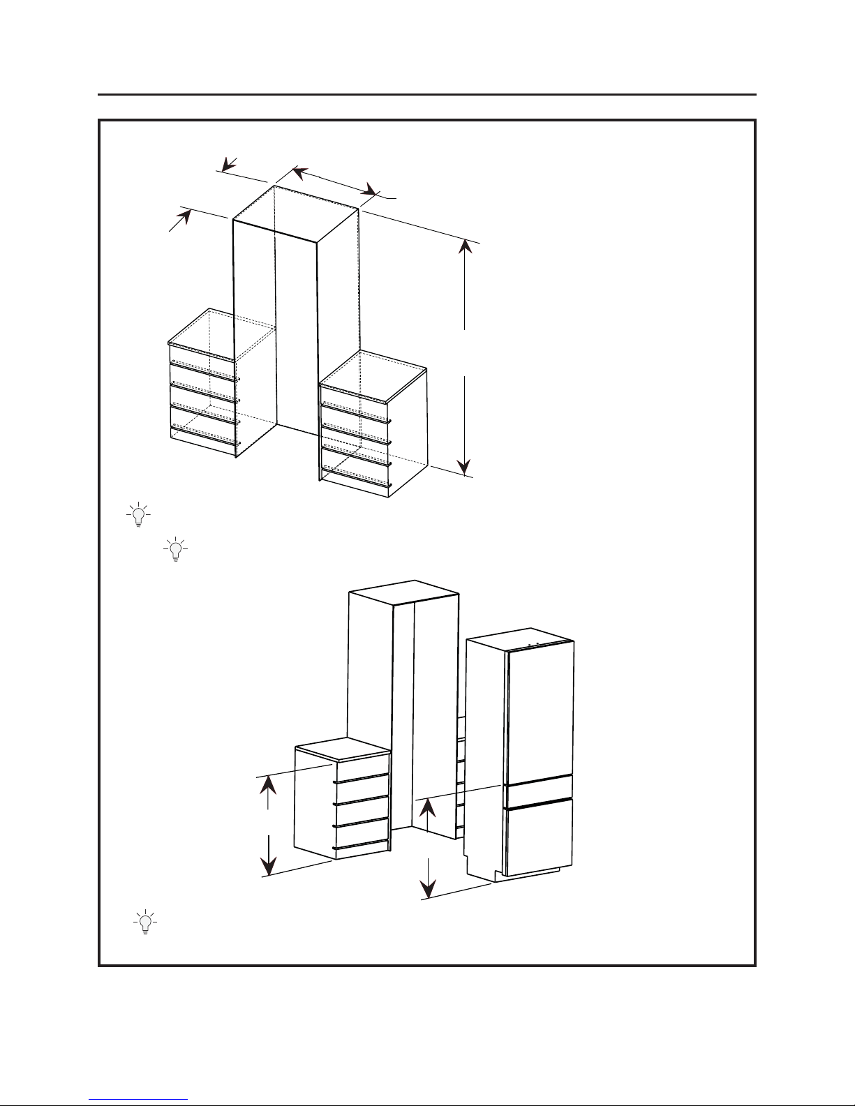
34 3/8”
34 3/8”
Height options
80” or * 84“
25” min. depth
30” Finished Width
Design Tip: It is possible to align your refrigerator drawer with adjacent cabinetry for a completely integrated
look.
Design Tip: We recommend finishing the inside surface of the enclosure a min. of 4” from the front face.
Design Tip: If using 84” enclosure, consider adding a finished valence above the refrigerator case.
Cabinet Enclosure Dimensions For Fully Integrated Instructions
The cutout depth must be 25"for
flush installations.
• The front face of the refrigerator fits
flush with 25"depth adjacent
cabinets.
• The refrigerator can fit into a 79-1/2"
minimum,
84-1/2" maximum high enclosure.
Although the refrigerator itself can
only be raised to 80 3/8”,
• The fresh food door panel can be
constructed to fill additional height;
see page 10.
Page 4
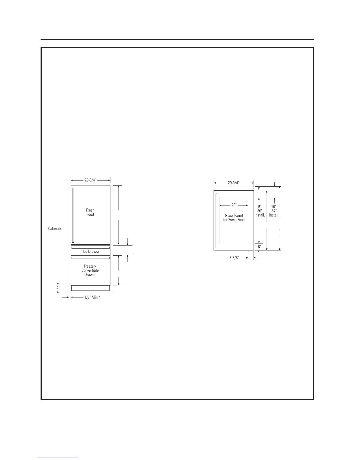
4
Design Guide
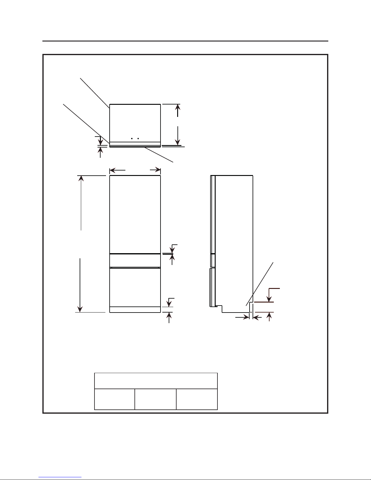
23 3/4”
29 1/2”
3/4”
1 1/4”
1/8”
6”
Height adjustable
from
79-3/8” to 80-3/8” *
4”
Case
Door
Panel
Clearance
Front with Panels
Side with Panels
Refrigerator Dimensions with 3/4” Panels
Top with Panels
Install Clearances
Top
1/8” / 3mm
Each Side
1/4” / 6mm
Rear
1/2” / 12mm
* The Refrigerator can be adjusted to fit into a cabinet space that is 83-3/8” to 84-
3/8” with the appropriate door panel kit.
(Case and Door only)
Page 5
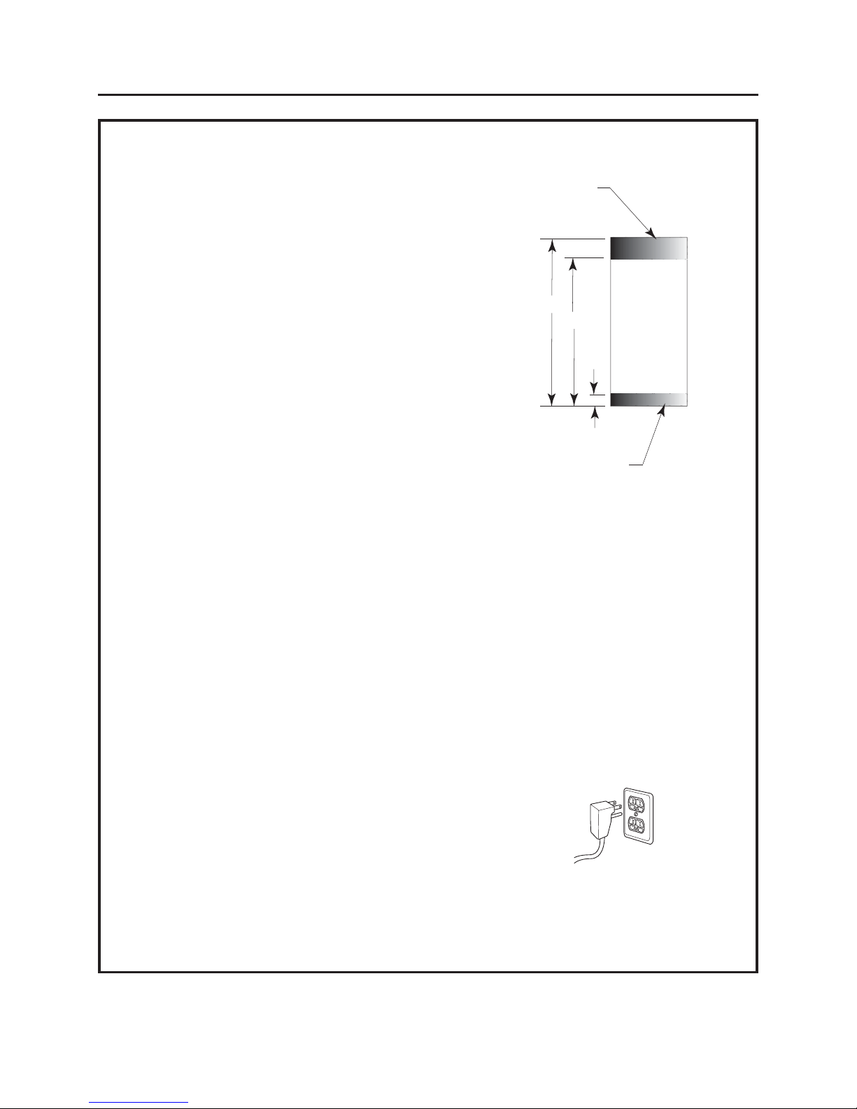
Water and Electrical Locations
Electrical and water supply should be located in shaded area only as shown.
PREPARING INSTALL WATER LINE
• A cold water supply is required
for automatic icemaker operation. The water pressure must be
between 40 and 120 p.s.i.
• Route 1/4" OD copper or GE SmartConnect™plastic tubing between
the house cold water line and the water connection location.
• Tubing should be long enough to extend to the front of the
encloasure.
• Water line can enter an opening through the floor or back wall.
• Install a shut-off valve between the icemaker water valve and cold
water supply in the home.
NOTE:
• It is recommended that the water shut-off valve be placed in a
location that is easily accessible. We do not advise placing it behind
the unit because of access difficulties. If it is necessary to install the
valve behind the unit, it must be located in the shaded area.
• Saddle type shut-off valves are included in many water supply kits, but are
not recommended for this application.
• The only GE-approved plastic tubing is supplied in the GE
SmartConnect
™
Refrigerator Tubing kits. Do not use any other plastic water supply line because the line is under
pressure at all times. Other types of plastic may crack or rupture with age and cause water damage to your home. GE
SmartConnect™Refrigerator Tubing Kits are available in the following lengths:
6' (1.8 m) WX08X10006, 15' (4.6 m) WX08X10015 & 25' (7.6 m) WX08X10025
• Commonwealth of Massachusetts Plumbing Codes 248CMR shall be adhered to. Saddle valves are illegal and use is not
permitted in Massachusetts. Consult with your licensed plumber.
Electrical Specifications
• A 115-volt, 60-Hz., 15- or 20-amp power supply is required. An individual properly grounded branch circuit or circuit
breaker is recommended.
• Install a properly grounded 3-prong electrical receptacle recessed into the back wall. Electrical must be located on rear
wall as shown.
NOTE: GFI (ground fault interrupter) is not recommended.
6”
80”
77”
A
nti-Tip location. Do
not obstruct this area.
Water and Electrical
Tube Outlet
Front view
Install Space
THE INSTALLATION SPACE
Design Guide
5
Where a standard 2-prong wall outlet is encountered, it
is your personal responsibility and obligation to have it
replaced with a properly grounded 3-prong wall outlet.
DO NOT, UNDER ANY
CIRCUMSTANCES, CUT
OR REMOVE THE THIRD
(GROUND) PRONG FROM
THE POWER CORD.
DO NOT USE AN ADAPTER PLUG TO CONNECT THE
REFRIGERATOR TO A 2-PRONG OUTLET.
DO NOT USE AN EXTENSION CORD WITH THIS
APPLIANCE.
GROUNDING THE REFRIGERATOR
IMPORTANT—(Please read carefully)
FOR PERSONAL SAFETY, THIS APPLIANCE MUST BE
PROPERLY GROUNDED.
The power cord of this appliance is equipped with
a 3-prong (grounding) plug which mates with a
standard three-prong (grounding) wall receptacle
to minimize the possibility of electric shock hazard
from this appliance.
Have the wall outlet and circuit checked by a
qualified electrician to make sure the outlet is
properly grounded.
Page 6
1-1/2”
1-1/4”
1”
3/4”
1-1/2”
1-1/4”
1”
3/4”
1/8”
SS European or Custom Panels
Top View
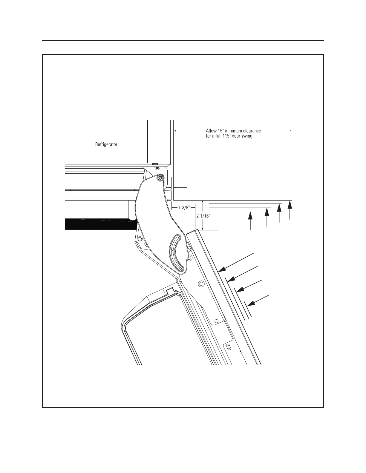
115° DOOR SWING
(factory setting)
6
Design Guide
Product Clearances
These refrigerators are equipped with a 2-position door
stop. The factory-set 115° door swing can be adjusted to
90° if clearance to adjacent cabinets or walls is restricted.
For 90° Door swing see page 7.
Not to scale
Page 7
For a 90º door
swing allow 5” min.
clearance to a wall,
for stainless steel
models.
1-1/2”
1-1/4”
1”
3/4”
1-1/2”
1-1/4”
1”
3/4”
1/8”
7
SS European or Custom Panels
Top View
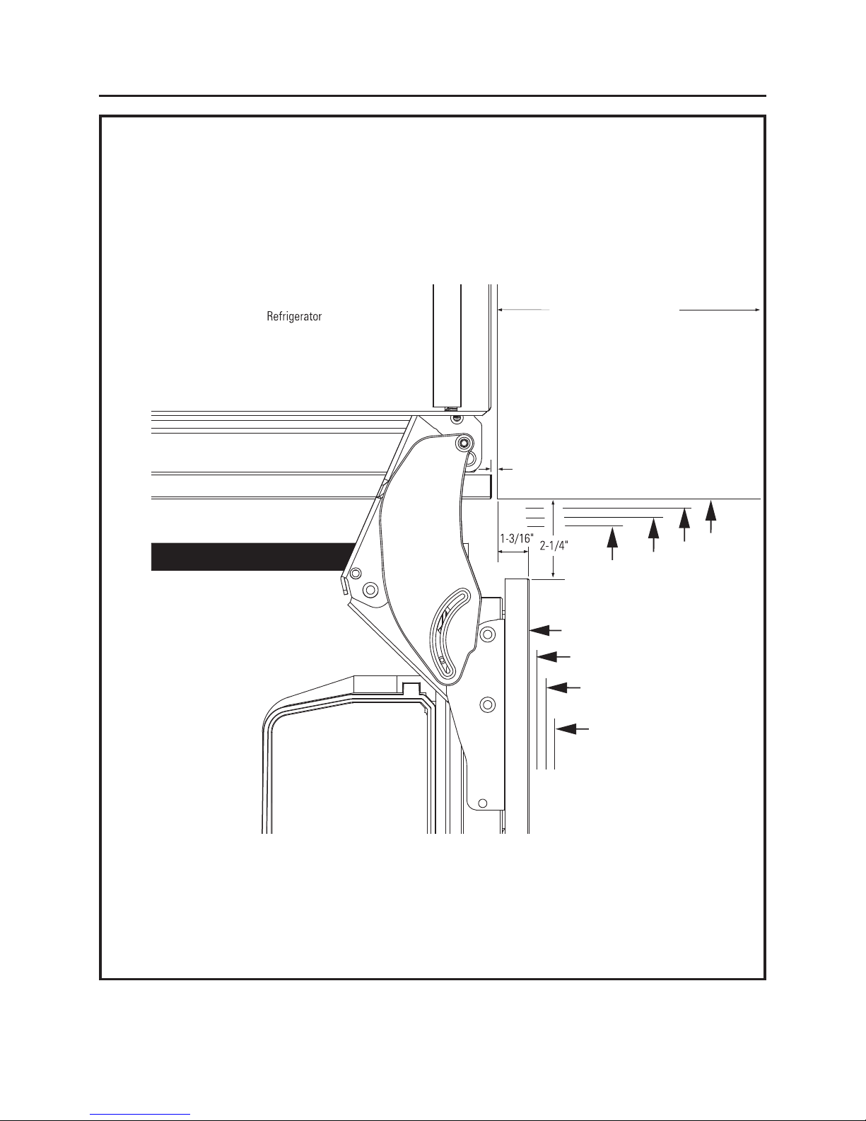
90° DOOR SWING
(optional setting)
Design Guide
Not to scale
Page 8
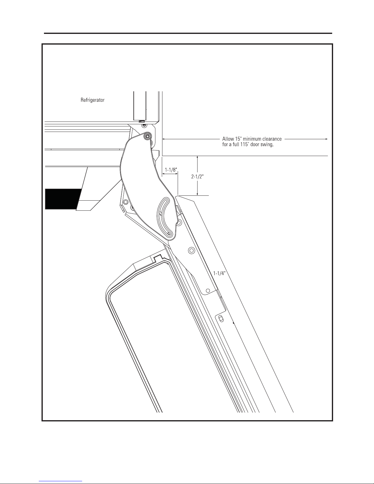
SS Professional Panels
Top View
115° DOOR SWING
(factory setting)
Design Guide
Product Clearances
These refrigerators are equipped with a 2-position door
stop. The factory-set 115° door swing can be adjusted to
90° if clearance to adjacent cabinets or walls is restricted.
For 90° Door swing see page 9.
8
Not to scale
Page 9
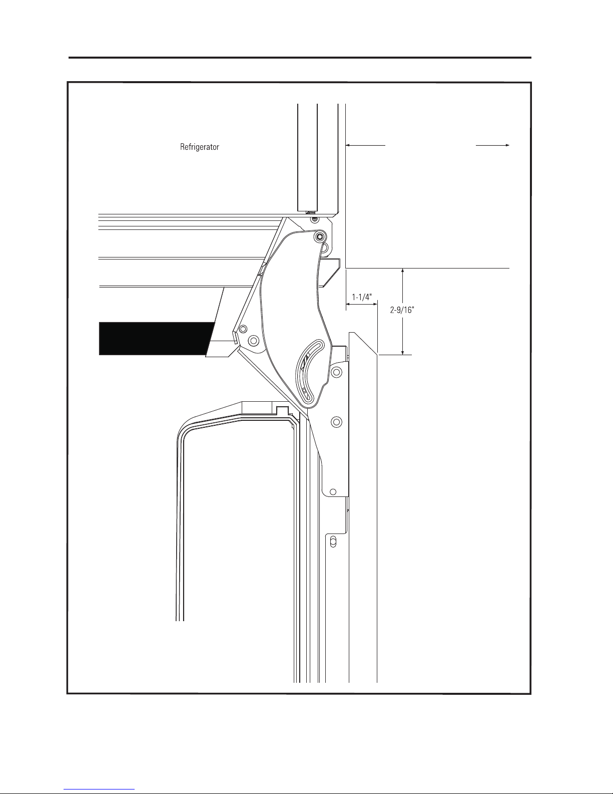
For a 90º door
swing allow 5” min.
clearance to a wall,
for stainless steel
models.
SS Professional Panels
Top View
90° DOOR SWING
(optional setting)
Design Guide
9
Not to scale
Page 10
Optional Accessory Kits #:
• Side-by-Side Installation Kit – ZUG30
• European handle kit - (3 handles) - WR12X10988
(can be purchased through GE Parts)
SS PANEL ACCESSORY & DIMENSIONS
3/4"-Thick Frame for Glass Door Options
For 80" High Installation
• Integrated – Model ZKGT300N LH & RH capable
• Professional – Model ZKGP300N LH & RH capable
For 84" High Installation (The door panel is not
reversible for the 84" Installations. A left or right-hand
door panel accessory must be purchased.)
• LH Integrated – Model ZKGT304NLH
• RH Integrated – Model ZKGT304NRH
• LH Professional – Model ZKGP304NLH
• RH Professional – Model ZKGP304NRH
NOTE: Each option also contains matching freezer and
Convertible drawer panels, handles and toekick.
3/4"-Thick Solid Door Panel Options
For 80" High Installation
• Integrated – Panel Model ZKST300N LH & RH capable
• Professional – Panel Model ZKSP300N LH & RH capable
For 84" High Installation (The door panel is not
reversible for the 84" Installations. A left or right-hand
door panel accessory must be purchased.)
• LH Integrated – Model ZKST304NLH
• RH Integrated – Model ZKST304NRH
• LH Professional – Model ZKSP304NLH
• RH Professional – Model ZKSP304NRH
NOTE: Each kit also contains matching freezer and
customizable drawer panels, handles and toekick.
10
*There must be a minimum 1/8" gap between panels and
surrounding cabinetry.
45-3/8”
49-3/8”
45-3/8” for 80” Installation
49-3/8” for 84” Installation
7-1/2”
22-3/4”
Design Guide
*
*Pro style window is slightly smaller..
Page 11
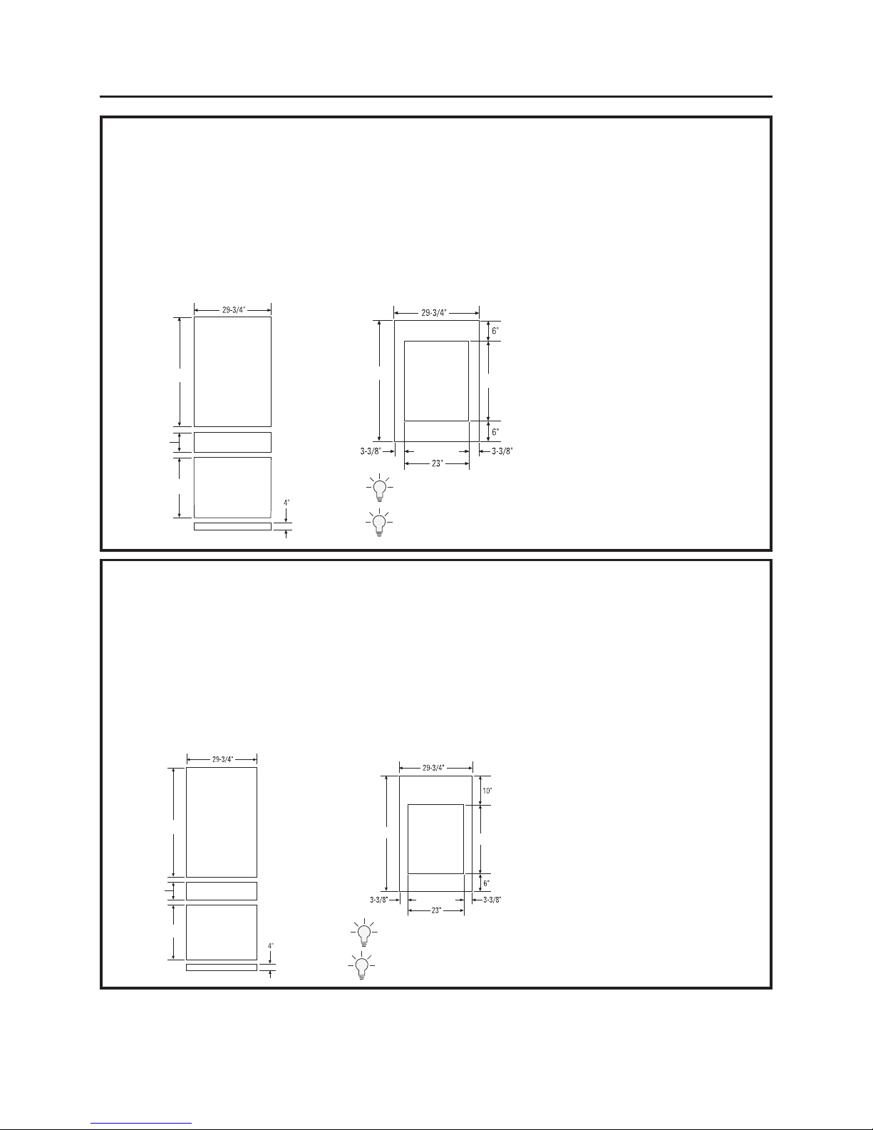
3/4" CUSTOM PANEL DIMENSIONS: 80" High Fully Integrated Installation
11
If you choose to install custom panels, they must be cut to
the dimensions shown. The panels will attach to the door
and drawers using a hook and bracket system.
EXTREMELY IMPORTANT: Custom wood panels must be at
least 3/4" thick where hooks and bracket hardware are
attached. Refer to Templates for hook and bracket location.
NOTE: This product is designed to handle ¾" panels that
are made of wood.
33-3/8" x 23" is the maximum opening for a glass
window. The opening may be smaller if desired.
Design Guide
IMPORTANT NOTE: Maximum panel weight:
A Fresh Food Door Panel: 33 lbs.
B Freezer Drawer Panel: 9 lbs.
C Convertibe Drawer Panel: 19 lbs.
45-3/8”
33-3/8”
A
B
C
45-3/8”
7-1/2”
22-3/4”
PANELS FOR SOLID DOOR AND DRAWERS
PANELS FOR GLASS DOOR
3/4" CUSTOM PANEL DIMENSIONS: 84" High Fully Integrated Installation
If you choose to install custom panels, they must be cut to
the dimensions shown. The panels will attach to the door
and drawers using a hook and bracket system.
EXTREMELY IMPORTANT: Custom wood panels must be at least
3/4" thick where hooks and bracket hardware are attached.
Refer to Templates for hook and bracket location.
NOTE: this product is designed to handle ¾" panels that
are made of wood.
33-3/8" x 23" is the maximum opening for a glass
window. The opening may be smaller if desired.
49-3/8”
33-3/8”
A
B
C
49-3/8”
22-3/4”
7-1/2”
PANELS FOR SOLID DOOR AND DRAWERS
PANELS FOR GLASS DOOR
Design Tip: Some amount of each panel will be visible on the interior side of
the unit. It is recommended that both sides of each panel be finished.
*Styles must be a min 3-3/8” to cover
aluminum door frame.
*Styles must be a min 3-3/8” to cover aluminum
door frame.
IMPORTANT NOTE: Maximum panel weight:
A Fresh Food Door Panel: 33 lbs.
B Freezer Drawer Panel : 9 lbs.
C Convertible Drawer Panel: 19 lbs.
Design Tip: If using custom panels, a cutom toe kick should be considered. The
Bottom of case is white.
Design Tip: Some amount of each panel will be visible on the interior side
of the unit. It is recommended that both sides of each panel be finished.
Design Tip: If using custom panels, a cutom toe kick should be considered.
The Bottom of case is white.
Page 12

MATERIALS REQUIRED
• 1/4" copper water line tubing or GE SmartConnect
™
Refrigerator Tubing kits
• Water shut-off valve
• Custom panels for fresh food door, freezer drawer
and Convertible drawer
• Velcro w/adhesive if using custom toekick.
FLOORING
For proper installation, this refrigerator must be
placed on a level surface of hard material that is at
the same height as the rest of the flooring. This
surface should be strong enough to support a fully
loaded refrigerator, or approximately 1,200 lbs.
NOTE: Protect the finish of the flooring. Cut a large
section of the cardboard carton and place under
the refrigerator where you are working.
TOOLS REQUIRED
• 5/32" Allen wrench
• Utility knife
• Stepladder
• Bucket
• Level
• Appliance hand truck
• Tubing cutter
• 7/16" open-end wrench
• 1-5/16" open-end wrench
• #2 Phillips screwdriver
• Drill and bit set
• 5/16" socket
• Safety glasses
• Pliers
• 3/8" ratchet
• Torx T-20, T-30 wrench
HARDWARE SUPPLIED
• Anti-tip bracket & screws
• Panel mounting brackets
• Door panel templates- Pub # 31-46543
• Water filter - Part # GSWF
• Drywall Anchors and screws
Installation Instructions
12
Page 13
13
Installation Instructions
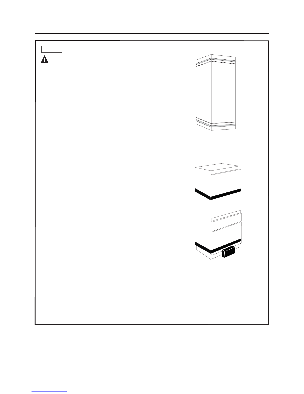
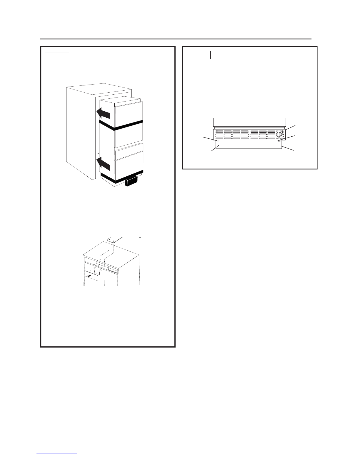
STEP 1 REMOVE PACKAGING
CAUTION: THE REFRIGERATOR IS
TOP-HEAVY. BE CAREFUL WHEN MOVING.
• Cut bands and tape on the top and bottom
of packaging with a utility knife.
• Unfold the cardboard seams and remove the top
of the packaging.
• Slide the remainder of the box off of the appliance.
You can use a box cutter to cut the remaining
cardboard being VERY CAREFUL not to scratch
the appliance.
• Remove the Styrofoam supports from around the unit.
• DO NOT remove door band or lower EPS banded
part until unit is ready to go into enclosure.
• Cut EPS skid at the sides near the front from the back
of the unit.
• Push unit forward & remove rear portion of the EPS
skid.
• Carefully lower rear onto the floor.
• Lean unit back slightly & remove front portion of the
EPS skid.
• Discard all unused packaging materials appropriately.
• The unit can now be moved using an appliance hand
truck or rolled on a properly protected floor by 2
people.
• Leave any protective film on the refrigerator until
installation is complete.
Page 14
80”
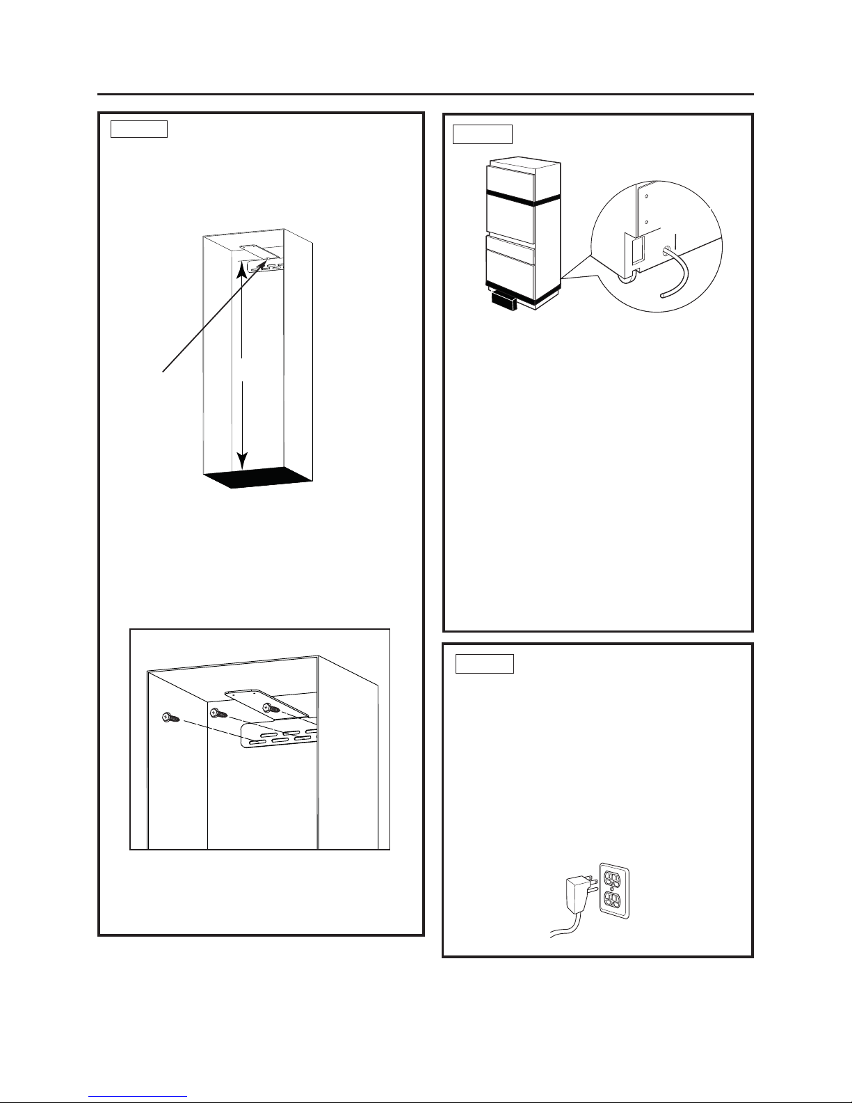
STEP 2 INSTALL ANTI-TIP BRACKET
• Inside Top Face of bracket should be installed at 80”.
“Slot” in bracket should to be placed in center of install
Space (Typically 15”)
• Mark (within slots, placement) stud and anchor positions
on brackets.
•Secure bracket using combination of studs & anchors.
•At least 1 stud must be engaged.However, please engage
as many studs as possible within the enclosure. A mininum
of three fasteners should be used for proper installation.
STEP 4 CONNECT POWER
• Plug the power cord into the socket.
• Check to make sure power to refrigerator is on by
opening the ice drawer (FF door will be banded shut)
to see if interior lights are on.
• The temperature controls are preset at 37°F for the
fresh food section and 0°F in both the freezer drawer
and customizable drawer.
• Allow 24 hours to stabilize before making
adjustments.
STEP 3 CONNECT WATER LINE
14
Installation Instructions
• Position appliance in front of enclosure.
• Locate and bring tubing to the front of the cabinet.
• Turn the water on to flush debris from line. Run about
a quart of water through tubing into a bucket; then
shut off water.
If needed cut the tubing to the proper length so it can
be attached to the water valve.
Copper Tubing:
• Slip a 1/4" nut and ferrule over both ends
of the copper tubing. Insert tube into the union fitting
on the unit and tighten nut to union.
• Turn on the water to check for leaks.
GE SmartConnect™ Tubing:
• Insert the end of the tubing into the refrigerator
connection. Tighten the compression nut until it is just
hand-tight.
• Tighten one additional turn with a wrench.
Overtightening can cause leaks!
• Turn on the water to check for leaks.
Water
Line Hole
Slot
Page 15
• Remove Top-Center trim cover from unit.
• Secure the unit to the Anti-tip bracket using both
machine screws & washers to engage the threaded
inserts in the anti-tip bracket.
• Hand start the screws until unit is in desired location
within the install space.
• Finalize unit install by tighening the screws fully.
• Reinstall Trim cover.
STEP 6
REMOVE TOEKICK AND VENT
The toekick must be removed to access
the leveling leg system.
• Remove band around EPS block in front of toekick.
• Remove and dispose of EPS block.
• Remove the solid portion of the toekick by pulling forward.
• Place the toekick, vent and screws out of the way so you
will have them for reinstallation.
Vent
Screw
Toekick
Vent
Screws
(behind
toekick)
Screw
15
Installation Instructions
STEP 5 SLIDE UNIT INTO ENCLOSURE
Roll the unit into the enclosure, being careful not to pinch
the water line or power cord.
• A long flat bar or yard stick may be needed to guide the
front edge of the anti-tip bracket over the unit.
• If space allows, you may also bend the front edge of the
bracket upward slightly, allowing it to clear the back of
the unit.
Page 16
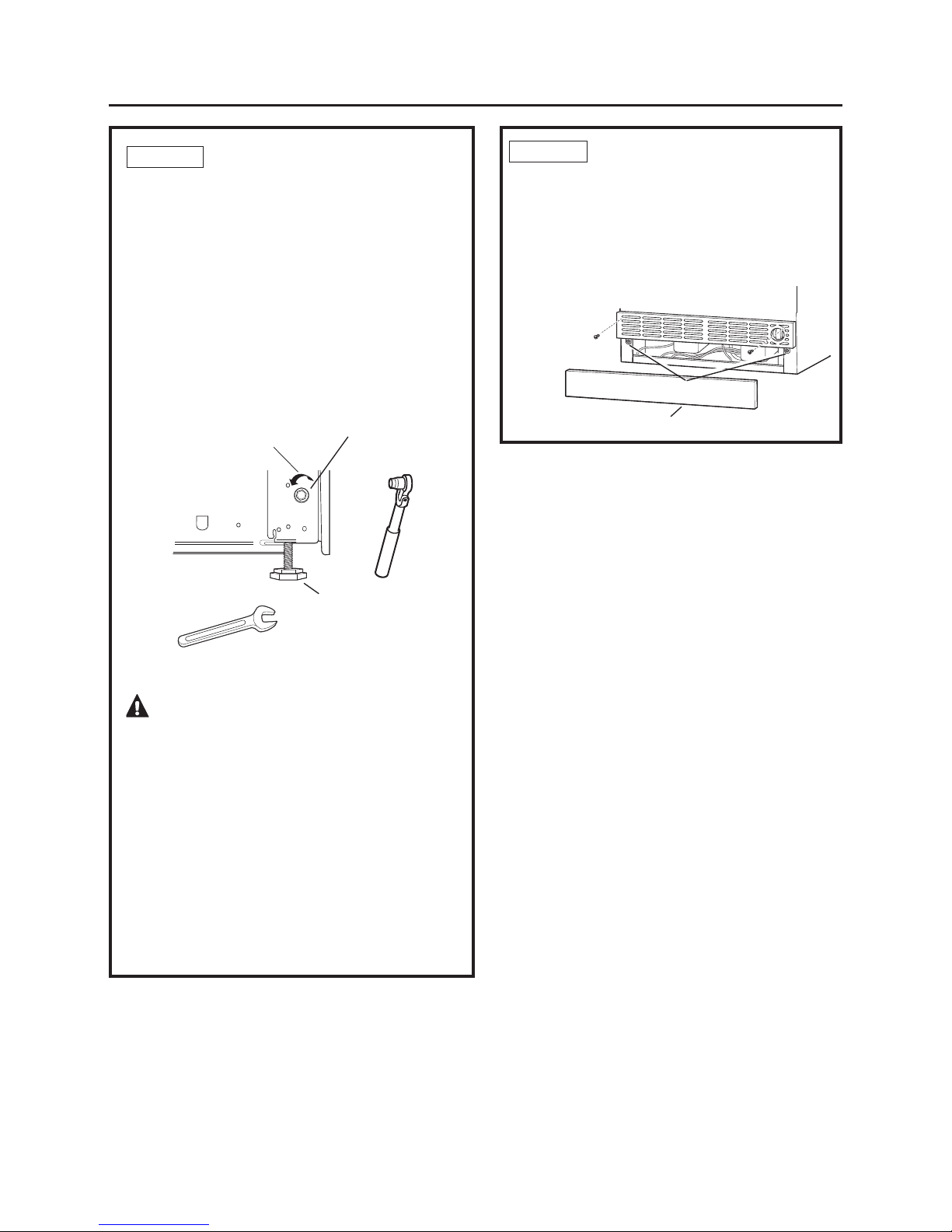
Up
16
Installation Instructions
CAUTION:
The rear leveling wheels and front leveling legs are
limited to a maximum height adjustment of 1". If the
installation requires more than 84-1/2" height, the
installer should elevate the refrigerator on a sheet
of plywood or runners. Cabinetry trim could also be
added across the top of the opening to shorten the
opening.
If you attempt to raise the refrigerator more than 1",
you will damage the front leveling legs and the rear
leveling wheels.
Leveling Leg
Hex Nut
Adjusts Rear
Wheels
Supplied Toekick
Vent Holes
Toekick Holes
STEP 7 LEVEL REFRIGERATOR
All models have 4-point leveling. The front is supported
by leveling legs; the rear is supported by adjustable
wheels. Both are accessible from the front of the
refrigerator.
• To level the back of the refrigerator, turn the 5/16" hex
nut located above the front wheels. Turn counter
clockwise to raise or clockwise to lower the
refrigerator.
• For front leveling, use a 1-5/16" open-end wrench.
• Adjust height of refrigerator to match installation
cutout opening. The refrigerator should be level and
plumb with cabinetry.
STEP 8 INSTALL TOEKICK AND VENT
• Locate the toekick, vent and screws (removed earlier).
• A custom toekick can be installed to match or
complement the surrounding cabinetry. Use the
supplied toekick as a template.
• Reinstall the vent using the screws removed earlier.
• Reinstall the toekick .
Page 17
17
Installation Instructions
STEP 9 REVERSE DOOR SWING (cont).
9. Install the screws on the fresh food compartment
cabinet in all 4 places. Screw them in about halfway.
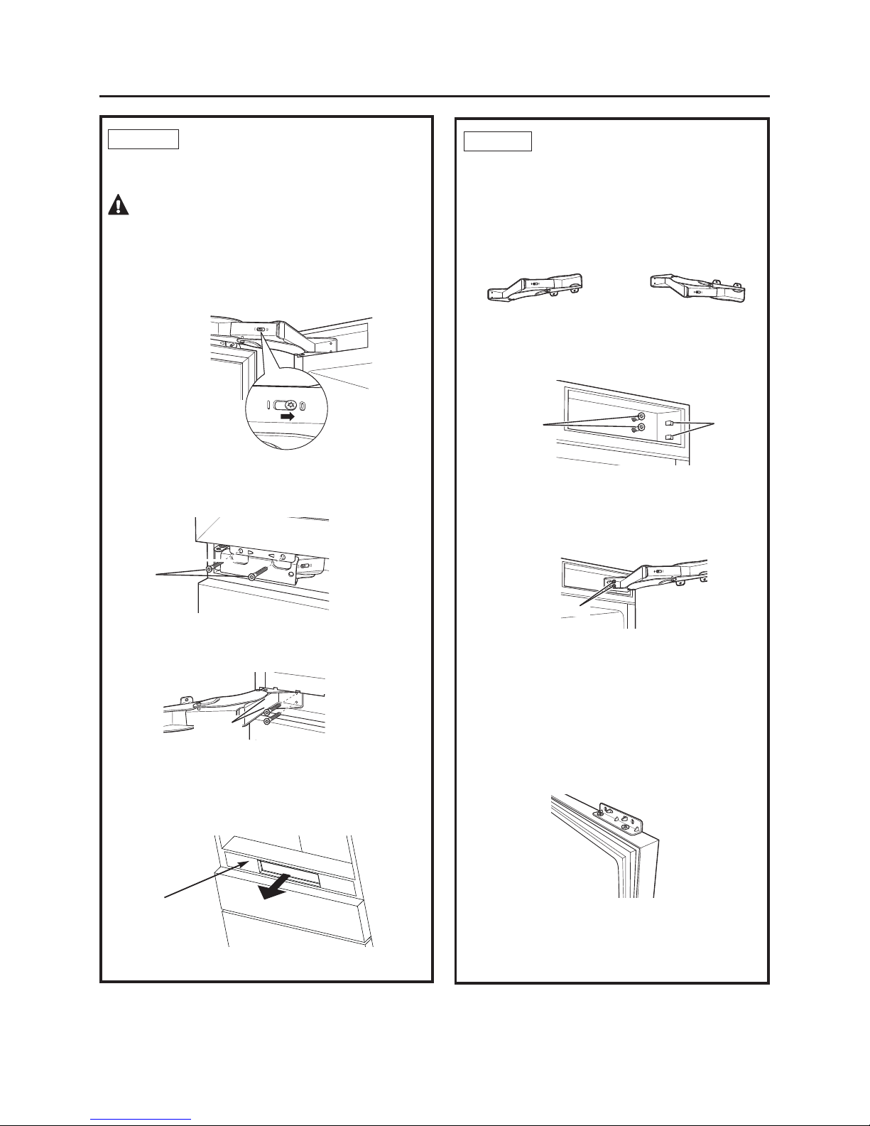
STEP 9 REVERSE DOOR SWING
(If needed)
Skip this step if door swing is satisfactory.
1. Open the fresh food door.
WARNING: THIS NEXT STEP IS
IMPORTANT FOR SAFE HANDLING OF AN
UNLOADED HINGE. DO NOT SKIP STEP 2.
2. Release the hinge springs by using a Torx T-20 wrench
to loosen the Torx screw from |to 0 on both hinges.
Close the door.
4. Open the hinges. Using a 5/32" Allen wrench, remove
the 2 screws per hinge that secure the hinge to the
refrigerator cabinet.
3. Using a 5/32" Allen wrench, remove the 2 screws per
hinge that secure the door to the refrigerator. Have
someone hold the door while removing these screws
to keep the door from falling.
8. The hinges will be reinstalled in opposite corners.
The hinge from the top will be turned over
and installed at the bottom of the fresh food
compartment. The hinge from the bottom will be
turned over and installed at the top of the fresh food
compartment.
10. To install the top hinge, turn the hinge in the proper
direction—the section of the bracket that will be
attached to the door should be at the bottom of the
hinge. Slide the hinge over the screws and seat the
tabs into the hinge pocket. Tighten the screws.
11. To install the bottom hinge, turn the hinge in the
proper direction—the section of the bracket that will
attach to the door should be at the top of the hinge.
Slide the hinge over the screws and seat the tabs
into the hinge pocket. Tighten the screws. Close
the hinge.
Screws
Screws
Top Hinge
Bottom Hinge
Slots for
Tabs
Screws
Screws
5. Remove the trim and hinge pocket from the top
of the refrigerator and install on the opposite sides.
6. Remove the trim and hinge pocket from the bottom
of the fresh food compartment. Remove the control panel
and gently place in the FZ drawer.
7. Reinstall the control panel.
12. Remove the hinge brackets from the door and reinstall
them on the opposite end, top and bottom.
Control Panel
Page 18
18
Installation Instructions
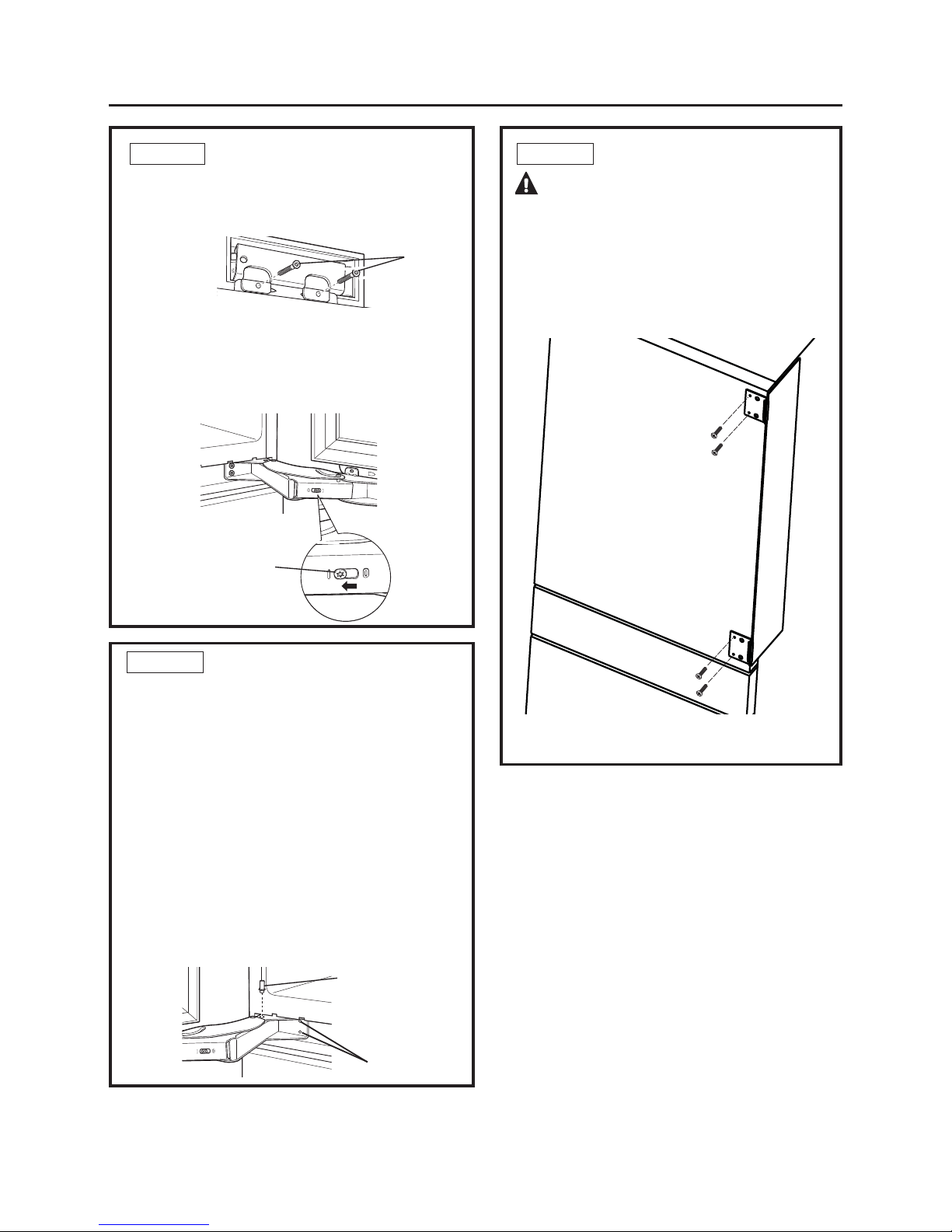
STEP 11 ATTACH HINGE GUARD
WARNING:
This appliance must be installed & operated with the
hinge guard in place !
1. Attach hinge guard by sliding flat part between case
and adjacent cabinetry.
2. Fasten guard to door front using 4 screws.
STEP 9 REVERSE DOOR SWING (cont).
14. install screws on the bottom hinge next.
15. Using a Torx T-20 wrench, tighten the tension on
the hinge springs by turning the screws from 0 to |.
13. With another person holding the door in place,
align the holes in the door hinge bracket with the
holes in the hinge. Install the screws to the top
hinge first .
Door
Screws
Use Torx
T-20 Wrench
STEP 10 ADJUST DOOR SWING (if needed)
NOTE: This refrigerator has a 2-position door stop. When
space does not allow the door to swing to 115°, you may
limit the door swing to a 90°
Skip this step if door opening is satisfactory for your
installation situation.
• Open the fresh food door to access the top and bottom
hinges.
• Loosen the bottom hinge screws that attached to the
unit
• Pull hinge forward slightly & insert hinge pin into the
hole nearest the unit.
• You may need to use a small hammer to fully seat
them in place.
• Retighten hinge screws.
• Repeat for top hinge.
Install 1 pin,
per hinge for
90° door stop.
Hinge screws
Page 19
19
Installation Instructions
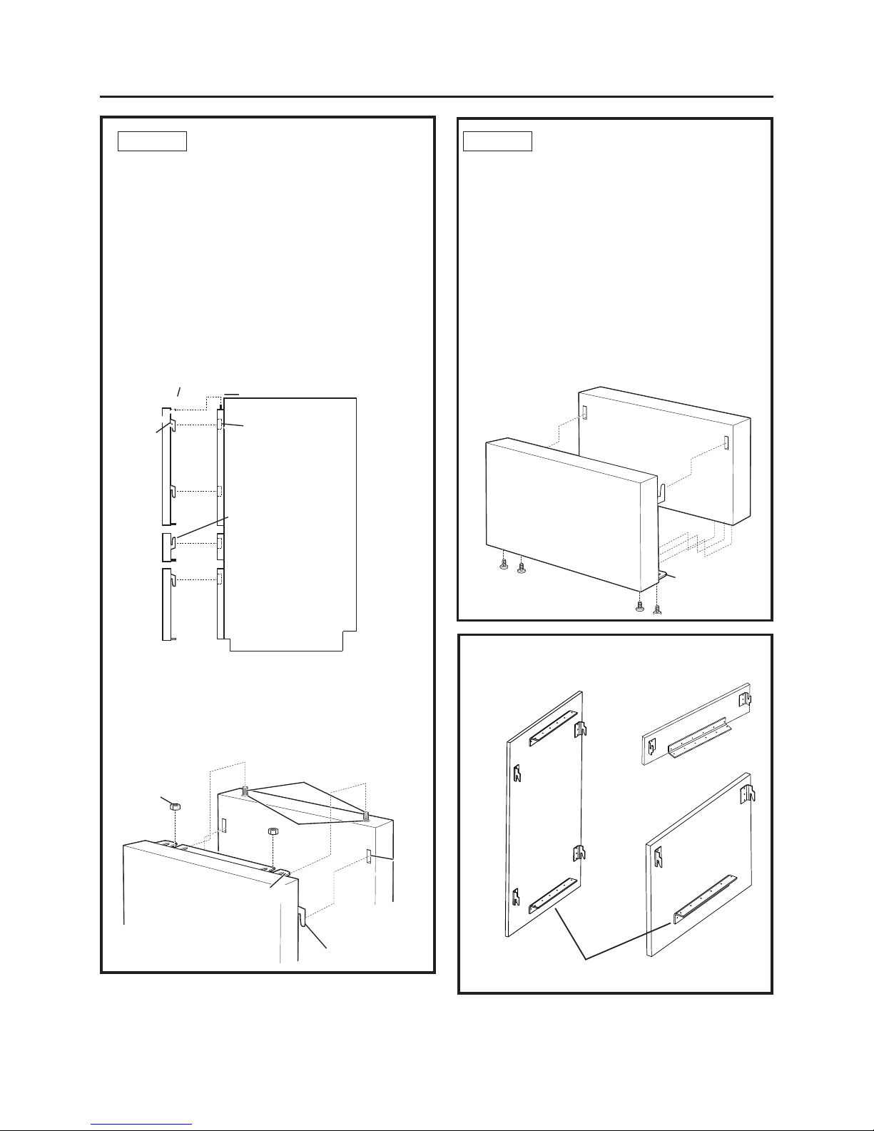
STEP 12 INSTALL DOOR AND DRAWER
PANELS
1. Remove all door and drawer hooks from the unit and
screw them to the custom panels, aligning them with the
lowest set of predrilled holes for Monogram Panel Kits on
the FF door panel.
2. Attach top L-Bracket to FF panel.
3. If you had custom handles made and they are not
currently attached to your panels, do so now.
4. Open the fresh food door to attach the fresh food panel.
5. Slide the hooks on the fresh food panel into the slots of the
door, and lower the hooks into place. Make sure the
bracket on the top of the panel slides over the screw posts
on top of the door. The brackets will rest on top of the nuts.
6. Adjust the screw posts up or down under the bracket
on top of the door to level the panel.
7. Lock the panel to the door by installing the nuts
provided onto the screw posts on top of the door.
Next, screw the L-bracket provided into the bottom of
the door and the panel.
Hooks
Top o f
Fresh Food
Panel Door
Nut
Nut
Slots
Bracket
Screw Post
STEP 12 INSTALL DOOR AND DRAWER
PANELS (cont).
7. Install the Freezer drawer panel by sliding the brackets
up into place (the opposite direction of the hooks on the
fresh food panel and Convertible drawer). .
8. Once the drawer panel is placed fasten the panel to the
drawer by screwing the bottom bracket into the panel
with the screws provided.
9. Repeat for the second drawer by sliding the hooks down
instead of up.
10. If using custom toekick attach the toekick panel by
placing Velcro on the back of the panel, and on the front
of the toekick. If using SS toekick it is magnetic.
11. Adjust drawer alignment using lower brackets as
needed to create uniform gaps.
Slots
Hooks
Screw Post
Bracket
Bra
cket
Back View of Panel Hooks and Bracket
Fresh
Food
Door
Convertible
drawer
Freezer
Drawer
Freezer
Drawer
The lower brackets on the Fresh Food & Convertible Drawer
should not be installed until after the panel is in place.
Hooks on the Freezer
drawer panel face up.
Page 20
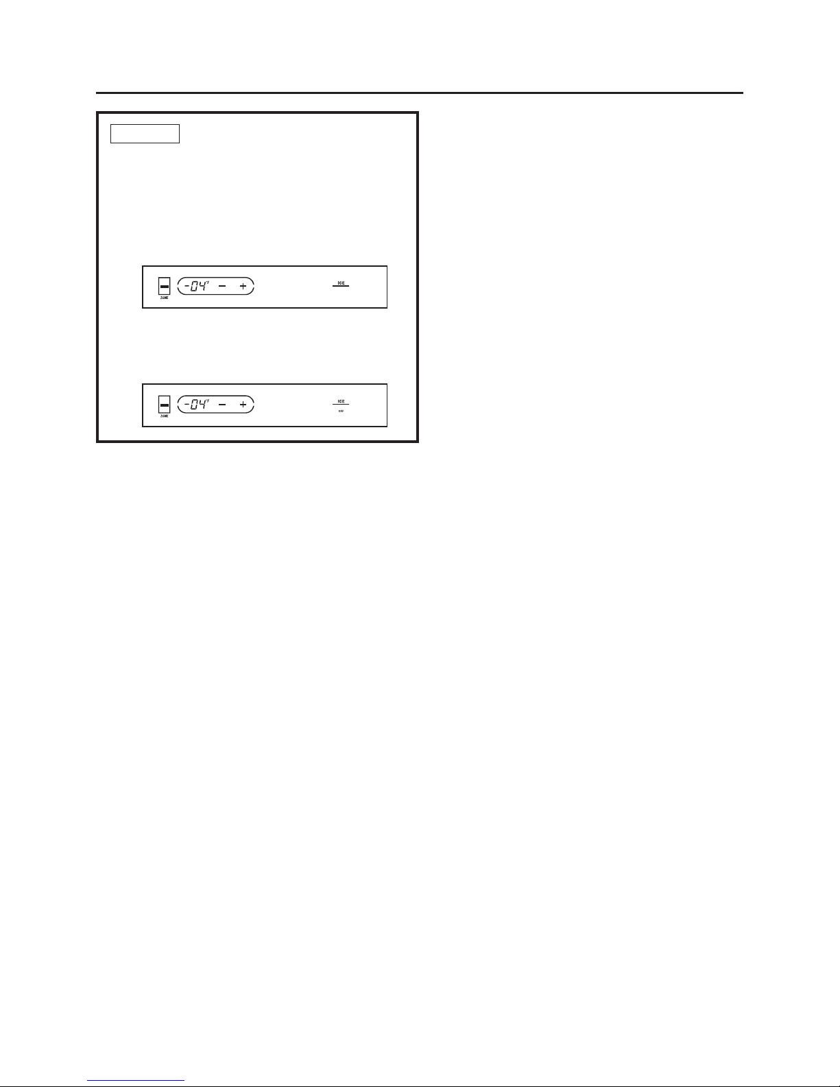
STEP 13 START ICEMAKER
• Press the ZONE indicator on the control pad twice
to select the freezer drawer. Press the ICE icon on the
right side of the control. A line will appear under ICE to
show that the icemaker is ON.
• Be sure nothing interferes with the sweep of the feeler
arm.
• Discard the first full bucket of ice cubes.
• To turn the icemaker off, press the ICE icon. The word
OFF appears below ICE to show that the icemaker
is OFF.
20
Installation Instructions
Page 21

Installation Instructions
21
Monogram
Monogram
Monogram
Monogram
84” Cutline
Door Top
80” cutline
Door Edge
6 1/8”
2 3/8”
3 7/8”
84” Cutline
Door Top
80” cutline
Door Edge
5 1/2
1 1/2”
3 7/8”
3.0”
Professional Panel Badge Template
European Panel Badge Template
3.3/4”
• To install badge, cut template that matches the panel style purchased, European or
Professional.
• Trim template for either 80” or 84” panel type.
• Align template at top corner nearest hing and place badge.
* For hinges on the left, flip template.
Shaded section should be between door edge & badge.
Page 22

Notes
22
Page 23

Notes
23
Page 24

NOTE: While performing installations described in this book,
safety glasses or goggles should be worn.
For Monogram®local service in your area, call
1.800.444.1845.
NOTE: Product improvement is a continuing endeavor
at General Electric. Therefore, materials, appearance and
specifications are subject to change without notice.
Page 25

Consignes de Sécurité
AVERTISSEMENT:
• Le haut de ces réfrigérateurs est lourd et ils doivent
être fixés pour éviter toute possibilité de basculement
vers l’avant. Une protection anti-basculement est
requise. Voir page 14 pour de plus amples informations
.•N’utilisez cet appareil qu’aux fins prévues
.•Réparez ou remplacez immédiatement tout cordon
électrique usé ou endommagé.
• Coupez l’alimentation électrique du réfrigérateur au
niveau du disjoncteur avant tout nettoyage ou
réparation.
• Les réparations doivent être effectuées par un
technicien de service qualifié.AVERTISSEMENT –
Frigorigène R600a
AVERTISSEMENT–Frigorigène
R600a
Avertissement : Cet appareil contient un fluide frigorigène
isobutane, R600a, un gaz naturel d’une grande compatibilité
environnementale. Il s’agit toutefois d’un combustible.
Veuillez respecter les avertissements suivants:
1) Lors de la manipulation, de l’installation et de l’utilisation
de cet appareil, prenez soin de ne pas endommager les
tubes de circulation du fluide frigorigène. .
2) L’entretien doit être effectué par un technicien de service
autorisé par le fabricant. Les pièces seront remplacées
par des pièces recommandées par le fabricant.
3) Les appareils réfrigérants contiennent des fluides
frigorigènes qui conformément à la législation fédérale
doivent être retirés avant la mise au rebut de l'appareil.
4) N’obstruez pas les évents dans l’enceinte prévue pour
l’appareil.
5) N’utilisez pas d’appareils ou autres moyens mécaniques
pour accélérer le processus de dégivrage.
6) N’endommagez pas le circuit du fluide frigorigène.
7) N’utilisez pas d’appareils électriques dans le
compartiment réfrigérateur de cet appareil.
25
AVANT DE COMMENCER
Lisez ces instructions entièrement et attentivement.
• IMPORTANT — Conservez ces instructions pour
l’inspecteur local. Respectez tous les codes et règlements
en vigueur.
• Remarque pour l’Installateur — Assurez-vous de
remettre ces instructions au Client.
• Remarque pour l’Utilisateur — Conservez ces
instructions avec votre notice d’utilisation pour toute
référence future.
•Niveau de compétence — L’installation de ce
réfrigérateur demande des connaissances de base en
mécanique, en menuiserie et en plomberie. L'installateur
est responsable de l'installation correcte de l'appareil. La
panne de l’appareil due à une mauvaise installation n’est
pas couverte par la garantie GE Électroménagers.
Consultez le manuel d’utilisation pour toute information
sur la garantie.
Pour les services locaux Monogram® dans votre secteur,
appelez le 1.800.444.1845.Pour les Pièces et Accessoires
Monogram, appelez 1.800.626.2002.
www.monogram.com
AVERTISSEMENT:
Cet appareil doit être correctement connecté à la terre. Se
référer à la section « Mise à la terre du réfrigérateur » à la
page 5.
Si le réfrigérateur reçu est endommagé, contactez
immédiatement votre vendeur ou votre installateur.
MISE EN GARDE :
A cause de la taille et du poids de ce réfrigérateur ainsi que
pour réduire le risque de blessure corporelle ou de
dommage au produit, DEUX PERSONNES SONT REQUISES
POUR UNE INSTALLATION CORRECTE.
TABLE DES MATIÈRES
Guide de conception
Dimensions de l’enceinte ....................26
Dimensions du réfrigérateur ............27
Emplacement pour le réfrigérateur 28
Mise à la terre du réfrigérateur ........26
Dimensions et dégagements ............27
Poignées intégrées pour ouverture de la
porte à 115° ..............................................29
Poignées intégrées pour ouverture de la
porte à 90° ................................................30
Poignées professionnelles pour ouverture
de la porte à 115° ..................................31
Poignées professionnelles pour ouverture
de la porte à 90° ......................................32
Accessoires et dimensions des panneaux
en acier inoxydable ................................33
Dimensions d’un panneau sur mesure de
¾ po ..............................................................34
Instructions d’installation
Outils, quincaillerie, matériaux ........35
Étape 1, retrait de l’emballage ........36
Étape 2, installation de la patte anti-
basculement ..............................................37
Étape 3, passage du tuyau d’eau ....37
Étape 4, branchement de
l’alimentation électrique ......................37
Étape 5, positionnement de l’appareil
dans son enceinte ..................................38
Étape 6, installation de la plinthe et de
l’évent ..........................................................38
Étape 7, mise à niveau du
réfrigérateu ................................................39
Étape 8, installation de la plinthe et de
l’évent ..........................................................39
Étape 9, installation de la plinthe et de
l’évent ..........................................................40
Étape 10, réglage de l’ouverture de
porte ......................................................40, 41
Étape 11, installation de la protection
de charnière ..............................................41
Étape 12, installation des panneaux
de porte et de tiroirs ..............................42
Étape 13, mise en marche de la
machine à glaçons ................................43
Gabarits ........................................................44
Observation ................................................45
Page 26

26
Guide de conception
34 3/8”
34 3/8”
Height options
80” or * 84“
25” min. depth
30” Finished Width
Conseil de conception: Il est possible d’aligner le tiroir du réfrigérateur avec le meuble adjacent pour un fini
complètement encastré.
Conseil de conception: Nous recommandons de faire terminer la surface intérieure de l’enceinte à une
distance minimale de 4 po de la face avant.
Conseil de conception: Si une enceinte d’une hauteur de 84 po est utilisée, pensez à utiliser une
bordure de finition au-dessus de la cuve du réfrigérateur.
Dimensions de l’enceinte pour instructions d’installation du réfrigérateur encastré
L'ouverture découpée doit avoir une
profondeur minimale de 25 po pour
un montage sans renfoncement.
• La face avant du réfrigérateur doit
être au même niveau que les
meubles adjacents avec une
profondeur de 25 po.
• Le réfrigérateur peut s’intégrer dans
une enceinte d’une hauteur entre 79
½ po et 84 ½ po.Toutefois, le
réfrigérateur peut seulement être
surélevé à une hauteur de 80-3/8 po.
• Le panneau du compartiment
réfrigérateur peut être fabriqué de
façon à couvrir la hauteur
supplémentaire; voir page 10.
Page 27

Cuve
27
Guide de conception
23 3/4”
29 1/2”
3/4”
1 1/4”
1/8”
6”
Height adjustable
from
79-3/8” to 80-3/8” *
4”
Por te
Panneau
Dégagement
Avant avec panneaux
Côté avec panneaux
Dimensions du réfrigérateur avec des panneaux de ¾ po
Dessus avec panneaux
Dégagements pour l’installation
Dessus
1/8po/ 3mm
Chaque côté
1/4po / 6mm
Arrière
1/2po / 12mm
* Le réfrigérateur peut être adapté pour s’encastrer dans une enceinte de 83-
3/8 po à 84-3/8 po avec le jeu de panneaux de porte approprié.
(Cuve et porte seulement)
Page 28

Emplacement des branchements électriques et des branchements à l’alimentation d’eau.
Les alimentations électrique et en eau doivent être placées dans les parties grisées comme indiqué sur le schéma cicontre.
PRÉPARATION DEL’INSTALLATION
DU TUYAU D’EAU
• Une alimentation d'eau froide est requise pour faire fonctionner la
machine à glaçons automatique. La pression de l’alimentation d’eau
doit rester dans une gamme de pression entre 40 et 120 p.s.i.
• Faites passer le tuyau d’1/4 po en cuivre ou le tuyau en plastique GE
SmartConnect™ entre la conduite d’eau froide du domicile et le
raccord de branchement d'eau.
• Le tuyau doit être suffisamment long pour atteindre l’avant du
réfrigérateur. Prévoyez une longueur de tuyau suffisante pour
prendre en compte la courbe menant au raccord à la conduite d’eau.
• Le tuyau d’eau peut passer par une ouverture dans le sol ou dans le
mur du fond.
• Installez un robinet entre le robinet de la machine à glaçons et le
tuyau d’alimentation en eau froide du domicile.
REMARQUE:
• Le robinet doit être placé dans un endroit facilement accessible. Il
n’est pas recommandé de le placer derrière l’appareil à cause de
l’accès difficile. S’il est nécessaire d’installer un robinet derrière
l’appareil, il doit être installé dans les zones grisées du schéma.
• Les robinets de type vanne à étrier sont souvent inclus dans les
trousses de branchement de l’alimentation d’eau, mais ne sont pas recommandés pour cette application.
• Les seuls tuyaux en plastique autorisés par GE sont fournis avec la trousse de tuyauterie pour réfrigérateur GE
SmartConnect™. N’utilisez pas d'autres tuyaux d'alimentation d'eau en plastique, cette ligne étant sous pression en
permanence. Certains types de plastique peuvent se fissurer ou se rompre avec le vieillissement et causer des dégâts
d'eau dans votre maison. Les trousses de tuyauterie pour réfrigérateur GE SmartConnect™ sont disponibles dans les
longueurs suivantes:
6 pi (1,8 m) WX08X10006, 15 pi (4,6 m) WX08X10015 & 25 pi (7,6 m) WX08X10025
• L’installation sera conforme aux codes de plomberie 248CMR du Commonwealth du Massachusetts. L’utilisation de robinetsvannes à étrier est interdite au Massachusetts. Demandez l’avis de votre plombier qualifié.Emplacement pour la patte antibasculement. N'obstruez pas cette zone.Branchement électrique et branchement à l’alimentation d’eau.Vue de face de
l’enceinte d’installation
Caractéristiques électriques
• Une alimentation électrique de 115 volts, 60 Hz et de 15 à 20 ampères est demandée. L’utilisation d’un circuit de
dérivation individuel correctement mis à la terre ou d’un disjoncteur est recommandée.
• Installez un boîtier électrique à 3 fiches correctement branché à la terre et encastré dans le mur du fond. La prise
électrique doit être située sur le mur du fond comme indiqué.
REMARQUE: L’utilisation d’un disjoncteur de fuite de terre n’est pas recommandée.
6”
80”
77”
A
nti-Tip location. Do
not obstruct this area.
Water and Electrical
Tube Outlet
Front view
Install Space
ENCEINTE POUR LE RÉFRIGÉRATEUR
Guide de conception
28
Si une prise murale standard 2-broches, il est de votre
responsabilité personnelle et l'obligation de la faire
remplacer par une prise murale à 3 broches mise à la
terre.
NE COUPEZ PAS OU N’ENLEVEZ
PAS, SOUS AUCUN PRÉTEXTE,
LA TROISIÈME BROCHE DE
MISE À LA TERRE DU
CORDON D’ALIMENTATION.
N’UTILISEZ PAS D’ADAPTATEUR POUR BRANCHER LE
RÉFRIGÉRATEUR À UNE PRISE BIPHASÉE.
N’UTILISEZ PAS DE RALLONGE AVEC CET APPAREIL.
MISE À LA TERRE DU RÉFRIGÉRATEUR
IMPORTANT—(À lire attentivement)
POUR DES RAISONS DE SÉCURITÉ, CET APPAREIL DOIT
ÊTRE CORRECTEMENT MIS À LA TERRE.
Le cordon d’alimentation de cet appareil est équipé
d’une fiche à trois broches (pour une mise à la terre)
qui s’adapte à la prise de courant standard à 3
broches (pour une mise à la terre) pour minimiser les
risques de chocs électriques par cet appareil.Faites
vérifier la prise murale et le circuit électrique par un
électricien qualifié pour s’assurer que le système est
correctement mis à la terre.
Dans le cas d’une prise biphasée, l’installateur a la
responsabilité et l’obligation de la remplacer par une
prise triphasée correctement mise à la terre.
Page 29

1-1/2”
1-1/4”
1”
3/4”
1-1/2”
1-1/4”
1”
3/4”
1/8”
Panneaux européens en acier
inoxydable ou sur mesureCoupe
horizontaleOUVERTURE DE PORTE À
115°(réglage d’usine)
29
Guide de conception
Dégagements
Ces réfrigérateurs sont équipés d’une butée de porte à
deux positions. L’ouverture de porte réglée en usine à
115° peut être réduite à 90° si les dégagements par
rapport aux meubles ou murs adjacents sont
restreints.Ouverture de la porte à 90°, voir page 7
Non à l’échelle
Page 30

For a 90º door
swing allow 5” min.
clearance to a wall,
for stainless steel
models.
1-1/2”
1-1/4”
1”
3/4”
1-1/2”
1-1/4”
1”
3/4”
1/8”
30
Panneaux européens en acier
inoxydable ou sur mesureCoupe
horizontaleOUVERTURE DE PORTE À
90°(réglages en option)
Guide de conception
Non à l’échelle
Page 31

Panneaux européens en
acier inoxydable ou sur
mesureCoupe
horizontaleOUVERTURE DE
PORTE À 115°(réglage
d’usine)
Guide de conception
Dégagements
Ces réfrigérateurs sont équipés d’une butée de porte à
deux positions. L’ouverture de porte réglée en usine à
115° peut être réduite à 90° si les dégagements par
rapport aux meubles ou murs adjacents sont
restreints.Ouverture de la porte à 90°, voir page 9
31
Non à l’échelle
Page 32

For a 90º door
swing allow 5” min.
clearance to a wall,
for stainless steel
models.
Panneaux européens en acier
inoxydable ou sur mesureCoupe
horizontaleOUVERTURE DE
PORTE À 90°(réglages en option)
Guide de conception
32
Non à l’échelle
Page 33

Accessoires en option #:
• Trousse d’installation côte-à-côte –ZUG30
• Trousse poignée européenne - (3 poignées) WR12X10988 (peut être achetée auprès du
service GE Parts)
ACCESSOIRES ET DIMENSIONS DES PANNEAUX EN ACIER INOXYDABLE
Option : Cadre de ¾ po d’épaisseur pour
porte en verre
Pour une installation d’une hauteur de 80 po
• Encastré – Modèle ZKGT300N, possibilité de poignée à
gauche ou à droite
• Professionnel –Modèle ZKGP300N, possibilité de
poignée à gauche ou à droite
Pour une installation d’une hauteur de 84 po (Le
panneau de porte n’est pas réversible pour les
installations à 84 po. Il est nécessaire d’acheter un autre
accessoire de panneau de porte pour poignée à gauche
ou à droite.)
• Encastré avec poignée gauche – Modèle ZKGT304NLH
• Encastré avec poignée droite – Modèle ZKGT304NRH
• Professionnel avec poignée gauche –Modèle
ZKGP304NLH
• Professionnel avec poignée droite –Modèle
ZKGP304NRH
REMARQUE: Chaque option contient également des panneaux,
des poignées et une plinthe assortis pour le congélateur et le
tiroir convertible.
Option : panneau de porte massif de ¾ po
d’épaisseur
Pour une installation d’une hauteur de 80 po
• Encastré –Modèle de panneau ZKST300N, possibilité de
poignée à gauche ou à droite
• Professionnel –Modèle de panneau ZKSP300N, possibilité
de poignée à gauche ou à droite
Pour une installation d’une hauteur de 84 po (Le panneau
de porte n’est pas réversible pour les installations à 84 po. Il
est nécessaire d’acheter un autre accessoire de panneau de
porte pour poignée à gauche ou à droite.)
• Encastré avec poignée gauche - Modèle ZKST304NLH
• Encastré avec poignée droite – Modèle ZKST304NRH
• Professionnel avec poignée gauche –Modèle ZKSP304NLH
• Professionnel avec poignée droite –Modèle ZKSP304NRH
REMARQUE: Chaque trousse contient également des panneaux,
des poignées et une plinthe assortis pour le congélateur et le tiroir
convertible.
33
*Il doit y avoir un dégagement minimum d’1/8 po entre les
panneaux et les meubles de cuisine adjacent.
45-3/8”
49-3/8”
45-3/8” for 80” Installation
49-3/8” for 84” Installation
7-1/2”
22-3/4”
Guide de conception
*
*Les fenêtres de type Pro sont légèrement plus
petites..
Page 34

A
B
C
49-3/8”
22-3/4”
7-1/2”
DIMENSIONS D’UN PANNEAU SUR MESURE DE ¾ po: Installation totalement
encastrée de 84 po de hauteur
49-3/8”
33-3/8”
PANNEAUX POUR PORTES ET TIROIRS MASSIFS
PANNEAUX POUR PORTE EN VERRE
Conseil de conception: Une partie de chaque panneau sera visible du côté
intérieur de l’appareil. Il est recommandé que la finition soit faite de chaque
côté du panneau.
*Les styles doivent être d’au moins 3-3/8 po
pour recouvrir le cadre de porte en aluminium.
REMARQUE IMPORTANTE: Poids maximal du
panneau:
A Panneau de porte du compartiment
réfrigérateur : 33 livres (15 kg)
B Panneau du tiroir congélateur : 9 livres (4 kg)
C Panneau du tiroir convertible : 19 livres (9 kg)
Conseil de conception: En cas d’utilisation de panneaux sur mesure, il est
important de penser à une plinthe sur mesure. Le bas de la cuve est de couleur
blanche.
45-3/8”
33-3/8”
DIMENSIONS D’UN PANNEAU SUR MESURE DE ¾ po Installation totalement
encastrée de 80 po de hauteur
34
En cas d’installation de panneaux sur mesure, ceux-ci
doivent être coupés aux dimensions indiquées. Les
panneaux se fixeront à la porte et aux tiroirs à l’aide d’un
système de crochets et de pattes.
TRÈS IMPORTANT: panneaux en bois sur mesure doit être
d'au moins 3 / 4 "d'épaisseur où les crochets et le
matériel de fixation sont attachés Reportez-vous à des
modèles pour le crochet et le lieu de fixation.
REMARQUE: Ce produit est conçu pour être utilisé avec des
panneaux en bois de ¾ po.Dimensions
maximales de l’ouverture pour une vitre en
verre : 33-3/8 po x 23 po. L’ouverture peut être
plus petite si vous le souhaitez.
Guide de conception
REMARQUE IMPORTANTE: Poids
maximal du panneau:
A Panneau de porte du compartiment
réfrigérateur : 33 livres (15 kg).
B Panneau du tiroir congélateur : 9
livres (4 kg).
C Panneau du tiroir convertible : 19
livres (9 kg).
A
B
C
45-3/8”
7-1/2”
22-3/4”
PANNEAUX POUR PORTES ET TIROIRS
MASSIFS
PANNEAUX POUR PORTE EN VERRE
*Les styles doivent être d’au moins 3-3/8 po pour
recouvrir le cadre de porte en aluminium.
Conseil de conception: Une partie de chaque panneau sera visible du côté
intérieur de l’appareil. Il est recommandé que la finition soit faite de chaque
côté du panneau.
Conseil de conception: En cas d’utilisation de panneaux sur mesure, il est
important de penser à une plinthe sur mesure. Le bas de la cuve est de
couleur blanche.
En cas d’installation de panneaux sur mesure, ceux-ci
doivent être coupés aux dimensions indiquées. Les
panneaux se fixeront à la porte et aux tiroirs à l’aide d’un
système de crochets et de pattes.
TRÈS IMPORTANT: panneaux en bois sur mesure doit être
d'au moins 3 / 4 "d'épaisseur où les crochets et le
matériel de fixation sont attachés Reportez-vous à des
modèles pour le crochet et le lieu de fixation.
REMARQUE: Ce produit est conçu pour être utilisé avec des
panneaux en bois de ¾ po.Dimensions
maximales de l’ouverture pour une vitre en
verre : 33-3/8 po x 23 po. L’ouverture peut être
plus petite si vous le souhaitez.
Page 35

ÉQUIPEMENT REQUIS
• Tuyau d’alimentation d’eau en cuivre d’ ¼ po ou
trousse pour réfrigérateur GE SmartConnect™
• Robinet d’arrêt d’eau
• Panneaux sur mesure pour la porte du
compartiment réfrigérateur, pour le tiroir
congélateur et pour le tiroir convertible
• Velcro avec côté adhésif pour la plinthe sur mesure.
SOL
Pour obtenir une installation correcte, le réfrigérateur
doit être placé sur une surface horizontale en
matériau dur qui est au même niveau que le reste du
sol. Cette surface doit être suffisamment solide pour
supporter le poids d’un réfrigérateur rempli, soit
environ 1,200 livres (550 kg).
REMARQUE: Protégez la finition du sol. Découpez un
grand morceau de carton et placez-le sous le
réfrigérateur sur l’aire de travail.
OUTILS REQUIS
• Clé Allen de 5/32 po
• Couteau à lame rétractable
• Escabeau
• Seau
• Niveau
• Diable
• Coupe-tube
• Clé anglaise de 7/16 po
• Clé anglaise de 1-1/4 po
• Tournevis Phillips cruciforme #2
• Perceuse et jeu de forets
• Douille 5/16 po
• Lunettes de sécurité
• Pinces
• Cliquet 3/8 po
• Torx T-20, T-30 clé
QUINCAILLERIE FOURNIE
• Patte anti-basculement et vis
• Pattes de montage des panneaux
• Gabarits de panneau de porte - Pub # 31-46543
• Filtre à eau - Pièce # GSWF
• Brides d’ancrage et vis pour cloison sèche
Instructions d’installation
35
Page 36

36
Instructions d’installation
ÉTAPE 1 RETRAIT DE L’EMBALLAGE
MISE EN GARDE: LE HAUT DE
VOTRE RÉFRIGERATEUR EST LOURD. FAITES
ATTENTION EN LE DÉPLAÇANT.
• Coupez les courroies et le ruban adhésif sur le haut et
sur le bas de l’emballage à l’aide d’un couteau à lame
rétractable.
• Dépliez le carton d’emballage et retirez le haut de
l’emballage.
• Retirez le reste de l’emballage en le faisant glisser de
l’appareil. Vous pouvez utilisez un couteau polyvalent
pour retirer le reste du carton d’emballage EN
PRENANT SOIN de ne pas rayer l’appareil.
• Retirez les supports en Styrofoam de l’appareil.
• NE retirez PAS la courroie maintenant la porte ou la
partie inférieure avant que l’appareil ne soit prêt à
être installé dans son enceinte.
• Découpez la palette en PSE sur les côtés avant par
l’arrière de l’appareil.
• Poussez l’appareil vers l’avant et retirez la partie
arrière de la palette en PSE.
• Posez doucement l’arrière de l’appareil sur le sol.
• Penchez légèrement l’appareil vers l’arrière et retirez la
partie avant de la palette en PSE.
• Mettez correctement au rebut les matériaux
d’emballage non-utilisés.
• Il est maintenant possible pour 2 personnes de
déplacer l’appareil à l’aide du diable ou de le faire
rouler jusqu’à un emplacement au sol correctement
protégé.
• Laissez tout film protecteur sur le réfrigérateur jusqu'à
la fin de l'installation.
Page 37

ÉTAPE 2 INSTALLATION DE LA PATTE
ANTI-BASCULEMENT
• La partie supérieure interne de la patte anti-basculement
doit être installée à une hauteur de 80 po. La « fente »
dans la patte doit être placée au centre de l’espace
d’installation (typiquement 15 po)
• Marquez (au niveau des fentes) les positions des montants
et des ancrages sur les pattes.
•Fixez la patte en utilisant les montants et des ancrages.
•Au moins un des montants doit être utilisé. Toutefois,
utilisez autant de montants possibles au sein de
l’ouverture. Au moins trois fixations doivent être utilisées
pour une installation correcte.
80”
ÉTAPE 4 BRANCHEMENT DE
L’ALIMENTATION ÉLECTRIQUE
• Branchez le cordon d’alimentation dans la prise.
• Vérifiez que le réfrigérateur soit bien branché en
ouvrant le bac à glaçons (la porte FF sera fermée par
une courroie) pour vérifier que les lumières
intérieures sont allumées.
• Les commandes de température sont préréglées sur
37°F (3°C) pour le réfrigérateur et sur 0°F (-18°C) pour
le tiroir du compartiment de congélation et du tiroir
convertible.
• Attendez 24 heures que la température se stabilise
avant de faire les réglages.
ÉTAPE 3 CONNECT CONDUITE D'EAU
37
Instructions d’installation
• Placez l’appareil devant l’enceinte.
• Localisez et amenez le tuyau vers l’avant du meuble
de cuisine.
• Ouvrez le robinet d’eau pour éliminer les débris dans
le tuyau. Faites couler environ 1 litre d’eau dans le
tuyau, recueillez l’eau dans un seau puis fermez le
robinet.
Si besoin est, coupez le tuyau à la longueur requise
pour qu’il puisse être connecté au robinet d’eau.
Tuyau en cuivre:
• Faites passer un écrou et un embout d’¼ po pardessus les deux extrémités du tuyau en cuivre.
Insérez le tuyau dans le raccord union sur l’appareil
et serrez l’écrou.
• Ouvrez le robinet d'eau pour vérifier l'absence de
fuites.
Tuyau GE SmartConnect™:
• Insérez l’extrémité moulée du tube dans le raccord
du réfrigérateur. Serrez l’écrou de compression à la
main.
• Serrez un tour supplémentaire avec la clé. Des fuites
peuvent survenir si l'écrou est trop serré !
• Ouvrez le robinet d'eau pour vérifier l'absence de
fuites.
Ouverture
pour le tuyau
d’eau
Fente
Page 38

ÉTAPE 5 POSITIONNEMENT DE
L’APPAREIL DANS SON ENCEINTE
Faites rouler l’appareil dans son enceinte, en s’assurant
de ne pas accrocher le tuyau d’eau ou le câble
d’alimentation.
• Une longue barre plate ou une règle de trente-six
pouces sera peut-être nécessaire pour guider le bord
avant de la patte anti-basculement par-dessus
l’appareil.
• S’il y a assez de place, vous pouvez légèrement courber
le bord avant de la patte vers le haut, permettant ainsi le
passage de l’appareil.
ÉTAPE 6
INSTALLATION DE LA PLINTHE ET
DE L’ÉVENT
La plinthe doit être enlevé pour accéder à la legstyle
nivellement
• Retirez la partie pleine de la plinthe en la tirant vers
l’avant.
•Placez la plinthe, l’évent et les vis à l’écart pour une
réinstallation future.
• Faites passer le tuyau d’eau par l’appareil jusqu’à ce
qu’il sorte par l’avant.
• Fixez le tuyau au sol à l’aide de ruban adhésif en
attendant que l’appareil soit placé dans l’enceinte.
Évent
Vis
Plinthe
Vis de
l’évent
(derrière la
plinthe)
Vis
• Retirez la protection de la garniture de l’appareil.
• Fixez l’appareil à la patte anti-basculement à l’aide des
vis de mécanique et des rondelles pour enfiler les
douilles filetées dans la patte anti-basculement .
• Commencez à visser les vis à la main jusqu’à ce que
l’appareil soit dans la position désirée dans l’enceinte.
• Finalisez l’installation en serrant les vis complètement.
•Réinstallez la protection de la garniture.
38
Instructions d’installation
Page 39

Up
ÉTAPE 8 INSTALLATION DE LA
PLINTHE ET DE L’ÉVENT
• Localisez la plinthe, l’évent et les vis (retirés
précédemment).
• Une plinthe sur mesure peut être installée pour être
assortie ou pour compléter les meubles alentours.
Utilisez la plinthe fournie comme modèle pour
découper la forme.
• Réinstallez l’évent à l’aide des vis retirées
précédemment.
• Réinstallez la plinthe.
39
Instructions d’installation
MISE EN GARDE:
Les roulettes arrière et les pieds avant de mise à niveau
sont limités à un réglage d’une hauteur maximale de 1
po. Si l’installation demande une hauteur supérieure à
84 ½ po, l’installateur doit surélever le réfrigérateur à
l’aide d’une plaque de contreplaqué ou des patins. Il est
également possible d’ajouter une moulure de meuble
sur le haut de l’ouverture pour réduire cette dernière.
Toute tentative de surélévation du réfrigérateur de
plus d’1 po va endommager les pieds avant et les
roulettes arrière de mise à niveau.
Pied de mise à niveau
Ecrou hexagonal
pour le réglage des
roulettes arrière
Plinthe fournie
Trous de ventilation
Ouvertures dans le
coup-de-pied
ÉTAPE 7 MISE À NIVEAU DU
RÉFRIGÉRATEUR
Tous les modèles possèdent quatre points de mise à
niveau. L’avant est soutenu par des pieds de mise à
niveau, l’arrière par des roulettes réglables. Les deux
sont accessibles par l’avant du réfrigérateur
• Pour mettre à niveau l’arrière du réfrigérateur, tournez
l’écrou hexagonal de 5/16 po situé au dessus des
roulettes avant. Tournez dans le sens des aiguilles
d'une montre pour rehausser le réfrigérateur et dans
le sens inverse des aiguilles d’une montre pour
l’abaisser.
• Pour mettre l’avant de niveau, utilisez une clé plate de
1¼ po.
• Réglez la hauteur du réfrigérateur pour correspondre
à l’ouverture découpée pour l’installation. Le
réfrigérateur doit être de niveau et d’aplomb avec les
meubles alentours.
Vers le haut
Page 40

40
Instructions d’installation
ÉTAPE 9 INVERSION DE L’OUVERTURE
DE PORTE (suite)
9. Installez les vis sur la cuve du compartiment
réfrigérateur aux 4 endroits. Vissez-les jusqu’à micourse.
ÉTAPE 9 INVERSION DE L’OUVERTURE
DE PORTE
(si nécessaire)
Sautez cette étape si l’ouverture de la porte est
satisfaisante.
1. Ouvrez la porte du réfrigérateur.
AVERTISSEMENT: L’ÉTAPE SUIVANTE
EST IMPORTANTE POUR LA MANIPULATION EN TOUTE
SÉCURITÉ D’UNE CHARNIÈRE NON CHARGÉE NE SAUTEZ PAS
L’ÉTAPE 2.
2. Libérez les ressorts de la charnière en utilisant une clé Torx
T-20 pour desserrer la vis Torx de la position 1 à la position
0 sur les deux charnières.
4. Ouvrez les charnières. A l’aide d’une clé hexagonale
de type Allen de 5/32 po, retirez les deux vis de
chaque charnière qui maintiennent la charnière sur
la cuve du réfrigérateur.
3. A l’aide d’une clé hexagonale de type Allen de 5/32
po, retirez les deux vis de chaque charnière qui
maintiennent la porte sur le réfrigérateur. Demandez
à quelqu’un de tenir la porte pendant que vous
retirez ces vis pour éviter que la porte ne tombe.
8. Les charnières seront installées dans les coins
opposés. La charnière supérieure sera retournée et
installée sur le bas du compartiment réfrigérateur. La
charnière inférieure sera retournée et installée sur le
haut du compartiment réfrigérateur.
10. Pour installer la charnière supérieure, placez la
charnière dans le bon sens - la partie du support
qui sera fixée à la porte doit être sur le bas de la
charnière. Faites glisser la charnière sur les vis et
placez les languettes dans le compartiment de la
charnière. Serrez les vis.
11. Pour installer la charnière inférieure, placez la
charnière dans le bon sens — la partie du support qui
sera fixé à la porte doit être sur le haut de la
charnière.Faites glisser la charnière sur les vis et
placez les languettes dans le compartiment de la
charnière. Serrez les vis. Fermez la charnière.
Vis
Vis
Charnière supérieure Charnière inférieure
Fentes
pour les
languettes
Vis
Vis
5. Retirez la garniture et le compartiment de charnière du
haut du réfrigérateur et installez-les sur le côté opposé.
6. Retirez la garniture et le compartiment de charnière du
bas du compartiment réfrigérateur. Retirez le tableau de
commande et placez-le délicatement dans le tiroir FZ.
7. Réinstallez le tableau de commande.
12. Retirez les supports de la charnière de la porte et
réinstallez-les sur le côté opposé, en haut et en bas.
Tableau de
commande
Page 41

41
Instructions d’installation
ÉTAPE 11 INSTALLATION DE LA
PROTECTION DE
CHARNIÈRE
AVERTISSEMENT:
Cet appareil doit être installé et utilisé avec la
protection de charnière en place !
1. Fixez la protection de charnière en faisant glisser la
partie plate entre la cuve du réfrigérateur et les meubles
de cuisine adjacents.
2. Fixez la protection sur l’avant de la porte à l’aide des 4
vis.
ÉTAPE 9 INVERSION DE L’OUVERTURE
DE PORTE (suite)
14. Installez ensuite les vis sur la charnière inférieure.
15. A l’aide d’une clé Torx T-20, resserrez la tension sur
les ressorts de la charnière en tournant les vis de la
position 0 à la position 1.
13. Avec l’aide d’une deuxième personne pour maintenir
la porte en place, alignez les trous dans le support de
la charnière de porte avec ceux dans la charnière.
Placez d’abord les vis dans la charnière supérieure.
Vis de
porte
Utilisez la
clé Torx T-20
ÉTAPE 10 RÉGLAGE DE L’OUVERTURE
DE PORTE (si nécessaire)
REMARQUE: Ce réfrigérateur possède 2 butées de position
d’ouverture. Quand l’espace ne permet pas l’ouverture de
la porte à 115°, vous pouvez limiter l’ouverture de porte à
90°.
Ignorez cette étape si l’ouverture de la porte est
satisfaisante pour l’installation.
• Ouvrez la porte du compartiment réfrigérateur pour
exposer les charnières supérieure et inférieure.
• Desserrez les vis de la charnière inférieure fixées à la
cuve
• Tirez la charnière légèrement vers vous et insérez l’axe
de la charnière dans le trou le plus proche de l’appareil.
• Vous pouvez utiliser un petit marteau pour les mettre en
place correctement.
• Resserrez les vis de la charnière.
• Répétez cette procédure pour
• Repeat for top hinge.
la charnière
supérieure.Installation
d’un axe par charnière
pour une ouverture de
porte à 90°.
Vis de charnière
Page 42

Les supports inférieurs sur la porte du réfrigérateur et sur le
tiroir convertible ne doivent pas être installés avant les
panneaux.
42
Instructions d’installation
ÉTAPE 12 INSTALLATION DES
PANNEAUX DE PORTE ET DE
TIROIRS
1. Retirez tous les crochets des portes et des tiroirs de
l’appareil et vissez-les sur les panneaux sur mesure, en les
alignant sur les trous prépercés les plus bas pour les
panneaux Monogram sur le panneau de porte FF.
2. Fixez le support en L supérieur au panneau FF.
3. Si vous avez fait fabriquer des poignées sur mesure et
qu’elles ne sont pas encore fixées aux panneaux, faites-le
maintenant.
4. Ouvrez la porte du réfrigérateur pour suspendre le panneau
approprié.
5. Faites glisser les crochets du panneau de la porte du
réfrigérateur dans les fentes de la porte et faites descendre
les crochets dans la bonne position. Assurez-vous que la
patte sur le haut du panneau se glisse par-dessus les vis
relieuses sur le haut de la porte. Les pattes reposeront sur le
dessus des écrous.
6. Ajustez les vis relieuses vers le haut ou vers le bas
sous la patte sur le haut de la porte pour mettre le
panneau de niveau.
7. Verrouillez le panneau sur la porte en plaçant les
écrous fournis sur les vis relieuses sur le dessus de la
porte.Ensuite, vissez la patte inférieure en L au bas de
la porte et du panneau.
Crochets
Haut du
panneau de la
porte du
réfrigérateur
Écrou
Écrou
Fentes
Patte
Vis relieuse
ÉTAPE 12 INSTALLATION DES
PANNEAUX DE PORTE ET DE TIROIRS
(suite)
7. Installez les panneaux de tiroir congélateur en insérant
les pattes en remontant vers le haut. (dans la direction
opposée aux crochets du panneau de la porte du
réfrigérateur et du tiroir convertible).
8. Lorsque le panneau du tiroir est en place, fixez-le au tiroir
en vissant la patte inférieure au panneau à l’aide des vis
fournies.
9. Répétez la procédure pour le deuxième tiroir en faisant
glisser les crochets vers le bas plutôt que vers le haut.
10. Si vous utilisez une plinthe sur mesure, fixez le panneau
de la plinthe en plaçant le Velcro au dos du panneau et
sur le devant de la plinthe. Si vous utilisez une plinthe en
acier inoxydable, il sera aimanté.
11. Ajustez l’alignement du tiroir en utilisant les pattes
inférieures si nécessaire pour créer un dégagement
uniforme.
Fentes
Crochets
Vis relieuse
Patte
Pa
tte
Vue de l’arrière des crochets et de la
patte du panneau
Porte du
compartiment
réfrigérateur
Tiroir
convertible
Tiroir
congélateur
Tiroir
congélateur
Crochets sur le
panneau du tiroir
congélateur vers le
haut.
Page 43

ÉTAPE 13 MISE EN MARCHE DE LA
MACHINE À GLAÇONS
• Appuyez deux fois sur le voyant ZONE sur le panneau de
commande pour sélectionner le tiroir congélateur.
Appuyez sur l’icône ICE (glaçon) sur le côté droit des
commandes. Une ligne apparaitra sous ICE (Glaçon) pour
indiquer que la machine à glaçons est activée.
• Vérifiez que rien n’interfère avec le déplacement du bras
de détection.
• Jetez le premier bac de glaçons.
• Pour arrêter la machine à glaçons, appuyez sur l’icône
ICE (glaçon). Le mot OFF (arrêt) apparaitra sous ICE
(Glaçon) pour indiquer que la machine à glaçons est
désactivée.
43
Instructions d’installation
Page 44

Instructions d’installation
44
Monogram
Monogram
Monogram
Monogram
84” Ligne de découpe
En Haut
80” Ligne de
découpe
Bord de la porte
6 1/8”
2 3/8”
3 7/8”
84” Ligne de découpe
En Haut
80” Ligne de
découpe
Bord de la porte
5 1/2
1 1/2”
3 7/8”
3.0”
Modèle Profession Badge Groupe
Modèle européen Badge Groupe
3.3/4”
• Pour installer insigne, modèle de découpe qui correspond au style du panneau acheté, européen ou professionnel.
• Trim modèle pour soit 80 "ou 84" type de panneau.
• aligner le gabarit dans le coin supérieur le plus proche badge Hing et le lieu.
* Pour les charnières sur la gauche, un modèle flip.
Section ombragée doit être compris entre bord de la porte et badge.
Page 45

Observations
45
Page 46

REMARQUE: Il est recommandé de porter des lunettes de
sécurité ou des lunettes étanches lors de l’installation de cet
appareil.
Pour les services locaux Monogram® dans votre
secteur, appelez le 1.800.444.1845.
REMARQUE: Au sein de General Electrics, nous nous
efforçons toujours d’améliorer nos produits. Ainsi, les
matériaux, l'aspect et les spécifications peuvent être
modifiés sans préavis.
Page 47

Información sobre Seguridad
ADVERTENCIA:
• Estos refrigeradores presentan inestabilidad y se
deberán asegurar a fin de evitar posibles inclinaciones
hacia adelante. Se requiere contar con protección antivolcaduras. Para más detalles, consulte la página 14.
• Use este electrodoméstico sólo para su propósito
original.
• De forma inmediata, repare o reemplace los cables del
servicio eléctrico que sufran daños o peladuras.
• Antes de realizar su limpieza o hacer reparaciones,
apague el disyuntor para desconectar la corriente.
• Cualquier reparación deberá ser realizada por un
técnico calificado del servicio.
ADVERTENCIA–Refrigerante
R600a
Advertencia: Este electrodoméstico cuenta con
refrigerante isobutano, R600a, un gas natural con alto
nivel de compatibilidad medioambiental. Sin embargo,
también es inflamable. Se solicita el cumplimiento de las
siguientes advertencias:
1) Al mover, instalar y operar el electrodoméstico, se
deberá tener cuidado de evitar dañar la tubería del
refrigerante.
2) El servicio técnico deberá ser realizado por personal
autorizado del servicio de la fábrica, y los componentes
podrán ser reemplazados por componentes de
reemplazo autorizados por el fabricante.
3) Los productos de refrigeración cuentan con
refrigerantes, los cuales de acuerdo con la ley federal
deberán ser eliminados antes de descartar el producto.
4) Mantenga las aberturas de ventilación en el espacio de
protección del electrodoméstico o en la estructura
incorporada libres de obstrucción.
5) No use dispositivos mecánicos u otros medios para
acelerar el proceso de descongelamiento.
6) No dañe el circuito del refrigerante.
7) No use dispositivos eléctricos dentro del
compartimiento de almacenamiento de comida del
electrodoméstico.
47
ANTES DE COMENZAR
Lea estas instrucciones en su totalidad y atentamente.
• IMPORTANTE — Conserve estas instrucciones
para uso del inspector local. Cumpla con todos los
códigos y ordenanzas gubernamentales.
• Nota para el Instalador — Asegúrese que el
Comprador conserve estas instrucciones.
• Nota para el Consumidor — Guarde estas
instrucciones con su Manual del Propietario para
referencia futura.
•Nivel de habilidad — La instalación de este
dispositivo requiere un nivel básico de habilidades de
mecánica, carpintería y plomería. La correcta
instalación del producto es responsabilidad del
instalador. Si se producen fallas en el producto debido a
una instalación inadecuada, la Garantía del Producto de
GE no cubrirá las mismas. Para obtener información
sobre la garantía, consulte el Manual del Propietario.
Para acceder al servicio local de Monogram, llame al
1.800.444.1845.
Para acceder a Piezas y Accesorios de Monogram,
llame al 1.800.626.2002.
www.monogram.com
ADVERTENCIA:
Este electrodoméstico deberá estar conectado a tierra de
forma adecuada.Consulte “Cómo Conectar a Tierra el
Refrigerador”, página 5.
Si el refrigerador que recibió está dañado, se deberá
comunicar de inmediato con su vendedor o contratista.
PRECAUCIÓN:
Debido al peso y tamaño de este refrigerador, y a fin de
reducir el riesgo de lesiones personales o daños sobre el
producto—SE DEBERÁ CONTAR CON DOS PERSONAS
PARA UNA INSTALACIÓN ADECUADA.
CONTENIDOS
Guía de Diseño
Dimensiones del Gabinete de
Protección....................................................48
Dimensiones del Refrigerador............49
El Espacio de Instalación ....................50
Conexión a Tierra del Refrigerador 50
Dimensiones y Espacio Libre..............50
Manijas Integradas con Giro de Puerta de
115º ..............................................................51
Manijas Integradas con Giro de Puerta de
90º ..................................................................52
Manijas Profesionales con Giro de Puerta
de 115º ........................................................53
Manijas Profesionales con Giro de Puerta
de 90º ..........................................................54
Accesorioy Dimensión del Panel SS. 55
Dimensiones del Panel a Medida
de 3/4" ..........................................................56
Instrucciones de Instalación
Herramientas, Equipo, Materiales....57
Paso 1, Retire el Envoltorio..................58
Paso 2, Instale el Soporte Anti-
Volcaduras ..................................................59
Paso 3, Inserte el Suministro de
Agua ..............................................................59
Paso 4, Conecte la Corriente ............59
Paso 5, Deslice la Unidad en el Espacio
de Protección ............................................60
Paso 6, Retire el Tope de Pie y la
Ventilación ..................................................60
Paso 7, Nivele el Refrigerador ..........61
Paso 8, Instale el Tope de Pie y la
Ventilación ..................................................61
Paso 9, Invierta el Giro de la
Puerta ....................................................62, 63
Paso 10, Ajuste el Giro de la
Puerta ..........................................................63
Paso 11, Añada el Protector de la
Bisagra ..........................................................63
Paso 12, Instale los Paneles de la
Puerta y el Cajón ....................................64
Paso 13, Encienda la Máquina de
Hacer Hielo..................................................65
Plantillas de Insignia ..............................66
Notas ............................................................67
Page 48

48
Guía de Diseño
34 3/8”
34 3/8”
Height options
80” or * 84“
25” min. depth
30” Finished Width
Consejo de Diseño: Es posible alinear el cajón de su refrigerador con gabinetes adyacentes para una apariencia completamente
integrada.
Consejo de Diseño: Recomendamos finalizar la superficie interior del espacio de protección a por lo menos 4" de la cara
frontal.
Consejo de Diseño: Si se usará un espacio de protección de 84”, se recomienda agregar un panel que cubra el espacio
sobre el cuerpo del refrigerador.
Dimensiones del Espacio de Protección del Gabinete para Instrucciones
Completamente Integradas
La profundidad del disyuntor deberá
ser de 25” para instalaciones al
mismo nivel.
• La cara frontal del refrigerador se
encuentra al mismo nivel que los
gabinetes adyacentes de 25” de
profundidad.
• El refrigerador puede calzar bien en
un espacio de protección con una
altura mínima de 79-1/2" y una
altura máxima de 84 1/2". Aunque el
refrigerador sólo se pueda levantar a
80 3/8”.
• Se puede construir el panel de la
puerta para alimentos frescos con la
finalidad de completar la altura
adicional; consulte la página 10.
Page 49

49
Guía de Diseño
23 3/4”
29 1/2”
3/4”
1 1/4”
1/8”
6”
Height adjustable
from
79-3/8” to 80-3/8” *
4”
Cubierta
Superior
Puerta
Panel
Espacio
Libre
Frente con Paneles
Costado con Paneles
Dimensiones del Refrigerador con Paneles de 3/4"
Parte Superior
con Paneles
Instalación en Espacio Libre
Parte Superior
1/8” / 3mm
Cada Lado
1/4” / 6mm
Parte Trasera
1/2” / 12mm
* El Refrigerador se podrá ajustar para que calce en un espacio de gabinete
de 83-3/8” a 84-3/8” con el kit del panel de la puerta adecuado.
(sólo Cubierta Superior y Puerta)
Page 50

Ubicaciones de Agua y Electricidad
El suministro de electricidad y agua deberá estar ubicado en un lugar con sombra como se muestra.
PREPARACIÓN PARA INSTALAR EL
SUMINISTRO DE AGUA
• Se requiere un suministro de agua fría para el funcionamiento de la
máquina de hielo automática. La presión del agua deberá estar entre
40 y 120 p.s.i.
• Haga circular una tubería de cobre de 1/4" OD o tubería de plástico
GE SmartConnect™ entre el suministro de agua fría de la casa y la
ubicación de la conexión de agua.
• La tubería deberá ser de una extensión suficiente como para llegar
hasta el frente del refrigerador. Deje una cantidad de tubería
suficiente para realizar una inclinación que llegue hasta la conexión
del suministro de agua.
• El suministro de agua puede ingresar a una abertura a través del piso
o la pared trasera.
• Instale una válvula de cierre entre la válvula de agua de la máquina
de hacer hielo y el suministro de agua fría en el hogar.
NOTA:
• Se recomienda que la válvula de cierre de agua se encuentre en una
ubicación de fácil acceso. No es aconsejable ubicarla detrás de la
unidad debido a dificultades de acceso. Si es necesario instalar la
válvula detrás de la unidad, deberá ser ubicada en un área con
sombra.
• Muchos kits de suministro de agua incluyen válvulas de cierre tipo montura, pero no se recomiendan para esta
aplicación.
• La única tubería aprobada por GE es suministrada en los Kits de Tuberías para Refrigerador de GE SmartConnect™.
No use ningún otro suministro de agua plástico, ya que el suministro se encuentra bajo presión en todo momento.
Otros tipos de plásticos podrán sufrir fisuras o rompeduras con el paso del tiempo y ocasionar problemas con el agua
en su hogar. Los Kits de Tuberías para Refrigerador de GE SmartConnect™ están disponibles en las siguientes
longitudes:
6' (1.8 m) WX08X10006, 15' (4.6 m) WX08X10015 & 25' (7.6 m) WX08X10025
• Se deberá cumplir con los Códigos de Plomería del Commonwealth de Massachusetts 248CMR. Las válvulas tipo
montura son ilegales y su uso está prohibido en Massachusetts. Consulte a un plomero matriculado.
Especificaciones Eléctricas
• Se requiere un suministro de corriente de 115 voltios, 60-Hz., 15 o 20 amperes. Se recomienda el uso de un circuito
individual derivado o un disyuntor correctamente conectado a tierra.
• Instale un receptáculo eléctrico de 3 patas correctamente conectado a tierra en la pared trasera. El receptáculo
eléctrico deberá estar ubicado en la pared trasera como se muestra.
NOTA: No se recomienda el uso de un Interruptor de Falla de Tierra (GFI).
6”
80”
77”
A
nti-Tip location. Do
not obstruct this area.
Water and Electrical
Tube Outlet
Front view
Install Space
EL ESPACIO DE INSTALACIÓN
Guía de Diseño
50
En caso de contar con un tomacorriente de pared de 2
cables, es su responsabilidad y obligación reemplazarlo
por un tomacorriente de pared de 3 cables
correctamente conectado a tierra.
NUNCA, BAJO NINGUNA
CIRCUNSTANCIA, CORTE
NI ELIMINE EL TERCER
CABLE (TIERRA) DEL
CABLE DE CORRIENTE.
NO USE UN ENCHUFE ADAPTADOR PARA CONECTAR EL
REFRIGERADOR A UN TOMACORRIENTE DE 2 PATAS. NO
USE UN PROLONGADOR CON ESTE ELECTRODOMÉSTICO.
CONEXIÓN A TIERRA DEL
REFRIGERADOR
IMPORTANTE – (Lea detenidamente)
PARA SU SEGURIDAD PERSONAL, ESTE
ELECTRODOMÉSTICO DEBERÁ ESTAR ADECUADAMENTE
CONECTADO A TIERRA.
El cable de corriente de este electrodoméstico cuenta
con un enchufe de 3 cables (conexión a tierra) que se
conecta a un tomacorriente de pared estándar de 3
cables (conexión a tierra) para minimizar el riesgo de
posibles descargas eléctricas por parte del mismo.
Contrate a un electricista calificado para que controle el
tomacorriente y el circuito eléctrico para asegurar que
el enchufe esté correctamente conectado a tierra.
Page 51

1-1/2”
1-1/4”
1”
3/4”
1-1/2”
1-1/4”
1”
3/4”
1/8”
Vista Superior de los Paneles
SS Europeos o A MedidaGIRO
DE PUERTA DE 115º(original de
fábrica)
51
Guía de Diseño
Espacios Libres del Producto
Estos refrigeradores están equipados con un dispositivo de
detención de la puerta de 2 posiciones. El giro de la puerta de
115º original de fábrica se podrá a justar a 90º si el espacio libre
hasta los gabinetes adyacentes o paredes es restringido. Para
que la puerta gire a 90º, consulte la página 7.
No a escala
Page 52

For a 90º door
swing allow 5” min.
clearance to a wall,
for stainless steel
models.
1-1/2”
1-1/4”
1”
3/4”
1-1/2”
1-1/4”
1”
3/4”
1/8”
52
Vista Superior de los Paneles SS
Europeos o A MedidaGIRO DE
PUERTA DE 90º(opcional)
Guía de Diseño
No a escala
Page 53

Vista Superior de los
Paneles SS
ProfesionalesGIRO DE
PUERTA DE 115º(original de
fábrica)
Guía de Diseño
Espacios Libres del Producto
Estos refrigeradores están equipados con un dispositivo de
detención de la puerta de 2 posiciones. El giro de la puerta de
115º original de fábrica se podrá a justar a 90º si el espacio libre
hasta los gabinetes adyacentes o paredes es restringido. Para
que la puerta gire a 90º, consulte la página 9.
53
No a escala
Page 54

For a 90º door
swing allow 5” min.
clearance to a wall,
for stainless steel
models.
Vista Superior de los
Paneles SS
ProfesionalesGIRO DE
PUERTA DE 90º(opcional)
Guía de Diseño
54
No a escala
Page 55

Kits de Accesorios Opcionales Nº:
• Kit de Instalación de Lado a Lado – ZUG30
• Kit de manija europea - (3 manijas) - WR12X10988(se
puede adquirir a través de Piezas de GE)
ACCESORIO Y DIMENSIONES DEL PANEL SS
3/4"- Opciones de Estructuras Gruesas para
Puertas de Vidrio
Para Instalación a una Altura de 80"
• Integrado – Modelo ZKGT300N LH & RH competente
• Profesional – Modelo ZKGP300N LH & RH competente
Para Instalación a una Altura de 84" (El panel de la
puerta no es reversible para Instalaciones a 84”. Se
deberá adquirir un accesorio para panel de puerta para
izquierda o derecha).
• LH Integrado – Modelo ZKST304NLH
• RH Integrado – Modelo ZKST304NRH
• LH Profesional – Modelo ZKSP304NLH
• RH Profesional – Modelo ZKSP304NRH
NOTA: Cada opción también cuenta con paneles para
cajones, manijas y topes de pie convertibles y para el
freezer.
3/4"- Opciones de Paneles de Puerta Sólidos y
Gruesos
Para Instalación a una Altura de 80"
• Integrado – Modelo de Panel ZKST300N LH & RH
competente
• Profesional – Modelo de Panel ZKST300N LH & RH
competente
Para Instalación a una Altura de 84" (El panel de la
puerta no es reversible para Instalaciones a 84”. Se
deberá adquirir un accesorio para panel de puerta para
izquierda o derecha.)
• LH Integrado – Modelo ZKST304NLH
• RH Integrado – Modelo ZKST304NRH
• LH Profesional – Modelo ZKSP304NLH
• RH Profesional – Modelo ZKSP304NRH
NOTA: Cada kit también cuenta con paneles para
cajones, manijas y topes de pie para el freezer y
adaptables.
55
*Deberá haber un espacio mínimo de 1/8” entre los paneles y los
gabinetes circundantes.
45-3/8”
49-3/8”
45-3/8” for 80” Installation
49-3/8” for 84” Installation
7-1/2”
22-3/4”
Guía de Diseño
*
*La ventana de estilo pro es un poco más
pequeña..
Page 56

49-3/8”
33-3/8”
A
B
C
45-3/8”
7-1/2”
22-3/4”
45-3/8”
33-3/8”
DIMENSIONES DEL PANEL A MEDIDA DE 3/4": Instalación Totalmente Integrada a
una Altura de 80”
56
Si decide instalar paneles a medida, se deberán cortar en
las dimensiones que se muestran. Los paneles serán
añadidos a la puerta y cajones, usando un sistema de
ganchos y soportes.
MUY IMPORTANTE: Los paneles de madera debe ser de al
menos 3 / 4 "de espesor en los ganchos y soporte de
hardware se adjuntan Consulte a las plantillas de
gancho y ubicación de los soportes.
NOTA: Este producto fue diseñado para sostener paneles
de ¾" construidos en madera. 33-3/8" x 23" es la
abertura máxima para una ventana de vidrio. La
abertura podrá ser más pequeña si así se desea.
Guía de Diseño
NOTA IMPORTANTE: Peso máximo del
panel:
A Panel de la Puerta para Alimentos
Frescos: 33 libras.
B Panel para Cajón del Freezer: 9 libras
C Panel del Cajón Convertible: 19 libras
PANELES PARA PUERTA Y VENTANAS SÓLIDAS
PANELES PARA PUERTA DE VIDRIO
DIMENSIONES DEL PANEL A MEDIDA DE 3/4": Instalación Totalmente Integrada a
una Altura de 84”
Si decide instalar paneles a medida, se deberán cortar en
las dimensiones que se muestran. Los paneles serán
añadidos a la puerta y cajones, usando un sistema de
ganchos y soportes.
MUY IMPORTANTE: Los paneles de madera debe ser de al
menos 3 / 4 "de espesor en los ganchos y soporte de
hardware se adjuntan Consulte a las plantillas de
gancho y ubicación de los soportes.
NOTA: Este producto fue diseñado para sostener paneles
de ¾" construidos en madera. 3-3/8" x 23" es la
abertura máxima para una ventana de vidrio. La
abertura podrá ser más pequeña si así se desea.
A
B
C
49-3/8”
22-3/4”
7-1/2”
PANELES PARA PUERTA Y
VENTANAS SÓLIDAS
PANELES PARA PUERTA DE VIDRIO
Consejo de Diseño: Cierta cantidad de cada panel será visible en el lado interior
de la unidad. Se recomienda que ambos lados de cada panel sean finalizados.
*Los estilos deberán ser como mínimo de 3-
3/8” para cubrir la estructura de la puerta de
aluminio.
*Los estilos deberán ser como mínimo de 3-3/8”
para cubrir la estructura de la puerta de aluminio
NOTA IMPORTANTE: Peso máximo del panel:
A Panel de la Puerta para Alimentos Frescos:
33 libras.
B Panel del Cajón del Freezer: 9 libras.
C Panel del Cajón Convertible: 19 libras.
Consejo de Diseño: Si usará paneles a medida, se recomienda usar un tope de
pie a medida. La parte inferior del cuerpo es blanca.
Consejo de Diseño: Cierta cantidad de cada panel será visible en el lado
interior de la unidad. Se recomienda que ambos lados de cada panel sean
finalizados.
Consejo de Diseño: Si usará paneles a medida, se recomienda usar un tope
de pie a medida. La parte inferior del cuerpo es blanca.
Page 57

MATERIALES REQUERIDOS
• Tubería de suministro de agua de cobre o de GE
SmartConnect™ de 1/4”.Kits de tubería del refrigerador
• Válvula de cierre de agua
• Paneles a medida de la puerta para alimentos frescos, cajón
del freezer y cajón Convertible
• Velcro con adhesivo si se usa un tope de pie a medida.
PISO
Para una instalación correcta, el refrigerador se deberá ubicar
en una superficie nivelada de material duro que posea la
misma altura en el resto del piso. Esta superficie deberá ser lo
suficientemente fuerte como para resistir el peso de un
refrigerador totalmente cargado o aproximadamente 1.200
libras (140 kg.).
NOTA: Proteja el acabado del piso. Corte una sección amplia de
cartón y coloque la misma debajo del refrigerador donde se
encuentra trabajando.
HERRAMIENTAS REQUERIDAS
• Llave Allen de 5/32"
• Cuchillo multiuso
• Escalera de dos hojas
• Balde
• Nivel
• Carro manual para electrodomésticos
• Cortador de tubos
• Llave de tuercas de 7/16"
• Llave de tuercas de 1-14"
• Destornillador Phillips nº2
• Kit de taladro y broca
• Enchufe de 5/16"
• Gafas de seguridad
• Pinzas
• Trinquete de 3/8"
• Torx T-20, T-30 Llave
MATERIALES SUMINISTRADOS
• Soporte anti-volcaduras y tornillos
• Soportes para montaje del panel
• Plantillas para el panel de la puerta- Pub nº 3146543
• Filtro de agua – Parte nº GSWF
• Anclajes para Paredes de Yeso y tornillos
Instrucciones de Instalación
57
Page 58

58
Instrucciones de Instalación
PASO 1 RETIRE EL EMBALAJE
PRECAUCIÓN
: EL REFRIGERADOR ES
INESTABLE. TENGA CUIDADO AL MOVERLO.
• Recorte las bandas y cintas de la parte superior e inferior del
embalaje con un cuchillo multiuso.
• Despliegue las juntas del cartón y retire la parte superior del
embalaje.
• Deslice el resto de la caja fuera del electrodoméstico. Puede
usar una cuchilla para cortar el resto del cartón con MUCHO
CUIDADO de no rayar el electrodoméstico.
• Retire los soportes de gomaespuma que se encuentran
alrededor de la unidad.
• NO retire la banda de la puerta ni la parte con bandas del
EPS inferior, hasta que la unidad esté preparada para ser
trasladada al espacio de protección.
• Recorte los deslizantes de EPS a los costados cerca del
frente desde la parte trasera de la unidad.
• Empuje la unidad hacia adelante y retire la parte trasera del
deslizante de EPS.
• De forma cuidadosa apoye la parte trasera en el piso.
• Incline la unidad hacia atrás de forma suave y retire la parte
frontal del deslizante de EPS.
• Descarte todos los materiales de embalaje sin uso de forma
adecuada.
• La unidad ya puede ser trasladada usando un carro manual
para electrodomésticos o girada sobre un piso
adecuadamente protegido por 2 personas.
• Deje cualquier película protectora sobre el refrigerador hasta
que la instalación sea completada.
Page 59

• Posicione el electrodoméstico frente al espacio de
protección.
• Encuentre y traiga la tubería al frente del gabinete.
• Abra y deje correr el agua a fin de eliminar desechos
del suministro. Deje correr alrededor de un cuarto de
galón de agua por la tubería a un balde; luego cierre
el suministro de agua.
De ser necesario, corte la tubería a fin de darle la
longitud necesaria de modo que se pueda añadir a la
válvula de agua.
Tubería de Cobre:
• Coloque una tuerca de 1/4" y una abrazadera de
refuerzo sobre ambos extremos de la tubería de
cobre. Inserte la tubería en la unión con la unidad y
ajuste la tuerca a la unión.
• Abra el suministro de agua para controlar que no
haya pérdidas.
Tubería de GE SmartConnect™:
• Inserte el extremo moldeado de la tubería en la
conexión del refrigerador. Ajuste a mano la tuerca de
compresión.
• Realice un ajuste adicional con un giro de llave. ¡Un
ajuste excesivo podrá ocasionar pérdidas!
• Abra el suministro de agua para controlar que no
haya pérdidas.
PASO 2 INSTALE EL SOPORTE ANTI-
VOLCADURAS
• La Cara Superior Interna del soporte se debería
instalar a 80". La “Ranura” del soporte se deberá
colocar en el centro del espacio de instalación
(Típicamente a 15”).
• Marque (dentro de las ranuras, ubicación) las
posiciones del montaje y el anclaje en los soportes.
•Asegure el soporte usando una combinación de montajes
y anclajes.
•Se deberá colocar por lo menos 1 montaje. Sin embargo,
se requiere colocar tantos montajes como sea posible
dentro del espacio de protección. Para una instalación
adecuada, se deberán usar por lo menos tres
sujetadores.
80”
PASO 4 CONECTE LA CORRIENTE
• Enchufe el cable de corriente en el tomacorriente.
• Asegúrese de que haya corriente en el refrigerador,
abriendo el cajón de hielo (la puerta FF se cerrará
con una banda) para ver si las luces interiores están
encendidas.
• Los controles de temperatura estarán programados
a 37° F para la sección de alimentos frescos y a 0°F
tanto en el cajón del freezer como en el cajón
adaptable.
• Permita que se estabilice durante 24 horas antes de
realizar ajustes.
PASO 3 CONECTAR LA LÍNEA DE AGUA
59
Instrucciones de Instalación
Abertura del
Suministro de
Agua
Ranura
Page 60

• Retire de la unidad la cubierta central superior de los
componentes.
• Asegure la unidad al soporte anti-volcaduras, usando
tornillos de máquina y arandelas para colocar las
inserciones roscadas en el soporte anti-volcaduras
• Enrosque a mano los tornillos hasta que la unidad se
encuentre en la ubicación deseada dentro del espacio
de instalación.
• Finalice la instalación de la unidad ajustando los
tornillos completamente.
• Vuelva a instalar la cubierta de los componentes.
PASO 6
RETIRE EL TOPE DE PIE Y LA
VENTILACIÓN
El zócalo debe ser removido para acceder a la
nivelación legstyle
• Retire la parte sólida del tope de pie empujando
hacia adelante.
• Coloque el tope de pie, la ventilación y los tornillos a
un costado, de modo que cuente con los mismos para
volver a realizar la instalación.
• Deje correr agua por la tubería a través de toda la
unidad, hasta que salga del frente de la unidad.
• Sujete con cinta adhesiva en el piso hasta que la
unidad haya sido empujada hasta el espacio de
resguardo.
Tornillo
Tope de
pie
Tornillos de
Ventilación
(detrás del
tope de pie)
Tornillo
60
Instrucciones de Instalación
PASO 5 DESLICE LA UNIDAD HASTA EL
ESPACIO DE PROTECCIÓN
Lleve la unidad hasta el espacio de protección, evitando
retorcer la tubería de suministro de agua y el cable de
corriente.
• Es posible que se requiera una barra larga y plana o
una regla para medir yardas, a fin de guiar el extremo del
frente del soporte anti-volcaduras sobre la unidad.
• Si el espacio lo permite, también puede inclinar el
extremo frontal del soporte un poco hacia arriba,
permitiendo que esto despeje la parte trasera de la
unidad.
Page 61

Up
61
Instrucciones de Instalación
PRECAUCIÓN:
Las patas niveladoras traseras y frontales cuentan con
un límite de ajuste de altura máxima de 1". Si en la
instalación se requiere una altura superior a 84-1/2", el
instalador deberá elevar el refrigerador sobre una
lámina de contrachapado o tirantes. También se podrá
agregar un ajuste a los gabinetes sobre la parte
superior de la abertura, a fin de acortar esta última.
Si intenta elevar el refrigerador más de 1”, dañará
las patas niveladoras frontales y las ruedas
niveladoras traseras.
Pata Niveladora
La Tuerca
Hexagonal Ajusta
las Patas Traseras
Tope de Pie Suministrado
Aberturas de Ventilación
Agujeros del Tope de Pie
PASO 7 NIVELE EL REFRIGERADOR
Todos los modelos cuentan con 4 puntos de nivelación.
La parte frontal está apoyada sobre patas niveladoras;
la parte trasera está apoyada sobre ruedas ajustables.
Es posible acceder a ambas desde la parte frontal del
refrigerador.
• A fin de nivelar la parte trasera del refrigerador, gire la
tuerca hexagonal de 5/16” que se encuentra ubicada
sobre las ruedas frontales. Gire en contra de las
agujas del reloj para levantar o a favor de las agujas
del reloj para bajar el refrigerador.
• Para nivelar la parte frontal, use una llave de tuercas
de 1-1/4".
• Ajuste la altura del refrigerador para que coincida con
la abertura de la instalación. El refrigerador deberá
estar nivelado y correctamente instalado entre los
muebles de cocina.
PASO 8 INSTALE EL TOPE DE PIE Y LA
VENTILACIÓN
• Ubique el tope de pie, la ventilación y los tornillos
(retirados anteriormente).
• Se puede instalar un tope de pie hecho a medida que
coincida o complemente los muebles que estén
alrededor. Use el tope de pie suministrado como
plantilla.
• Vuelva a instalar la ventilación usando los tornillos
retirados previamente.
•Vuelva a instalar el tope de pie.
Hasta
Page 62

62
Instrucciones de Instalación
PASO 9 GIRO DE PUERTA INVERSO
(cont).
9. Instale los tornillos en el gabinete del
compartimiento de alimentos frescos en los 4 lugares.
Atornille los mismos aproximadamente en el punto
intermedio.
PASO 9 GIRO DE PUERTA INVERSO (Si
es necesario)
Si está satisfecho con el giro de la puerta, saltee este
paso.
1. Abra la puerta de alimentos frescos.
ADVERTENCIA: EL SIGUIENTE
PASO ES IMPORTANTE PARA UN MANEJO
SEGURO DE UNA BISAGRA SIN CARGA. NO
SALTEE EL PASO 2.
2. Libere los resortes de la bisagra usando una llave Torx T-20
para aflojar el tornillo Torx de | a 0 en ambos resortes.
Cierre la puerta.
4. Abra las bisagras. Usando una llave Allen de 5/32",
retire los 2 tornillos por bisagra que aseguran la
bisagra al gabinete del refrigerador.
3. Usando una llave Allen de 5/32", retire los 2 tornillos
por bisagra que aseguran la puerta al refrigerador.
Pida a otra persona que sostenga la puerta,
mientras retira estos tornillos para evitar que la
puerta sufra una caída.
8. Las bisagras se volverán a instalar en esquinas
opuestas. La bisagra de la parte superior se dará
vuelta y se instalará en la parte inferior del
compartimiento de alimentos frescos. La bisagra de
la parte inferior se dará vuelta y se instalará en la
parte inferior del compartimiento de alimentos
frescos.
10. Para instalar la bisagra superior, gire la bisagra en
la dirección adecuada – la sección del soporte que
será añadido a la puerta se deberá encontrar en la
parte inferior de la bisagra. Deslice la bisagra sobre
los tornillos y coloque las lengüetas en el brazo de
la bisagra. Ajuste los tornillos.
11. Para instalar la bisagra inferior, gire la bisagra en la
dirección adecuada – la sección del soporte que será
añadido a la puerta se deberá encontrar en la parte
superior de la bisagra. Deslice la bisagra sobre los
tornillos y coloque las lengüetas en el brazo de la
bisagra. Ajuste los tornillos. Cierre la bisagra.
Tornillos
Tornillos
Bisagra Superior Bisagra Inferior
Ranuras
para
Lengüetas
Tornillos
Tornillos
5. Retire el brazo de la bisagra y el marco de la parte superior
del refrigerador e instale estos en los lados opuestos.
6. Retire el brazo de la bisagra y el marco de la parte inferior
del compartimiento de alimentos frescos. Retire el panel de
control y suavemente coloque el mismo en el cajón FZ.
7. Vuelva a instalar el panel de control.
12. Retire las tuercas de la puerta para volver a instalar
las mismas en la parte superior, inferior y extremo
opuesto.
Panel de Control
Page 63

Use una llave
Torx T-20.
63
Instrucciones de Instalación
PASO 11 INSTALE EL PROTECTOR DE
LA BISAGRA
ADVERTENCIA:
El protector de la bisagra deberá estar ya colocado
cuando el electrodoméstico sea instalado y utilizado.
1. Añada el protector de la bisagra deslizando la parte
plana entre la caja y los muebles circundantes.
2. Ajuste la bisagra al frente de la puerta usando 4 tornillos.
PASO 9 GIRO DE PUERTA INVERSO
(cont).
14. Luego instale los tornillos en la bisagra inferior.
15. Usando una llave Torx T-20, ajuste la tensión de los
tornillos de la bisagra girando los tornillos de 0 a |.
13. Con otra persona que sostenga la puerta en su lugar,
alinee las aberturas del soporte de las bisagras de la
puerta con las aberturas de la bisagra. Primero
coloque los tornillos en la bisagra superior.
Tornillos
de la
Puerta
PASO 10 AJUSTE EL GIRO DE PUERTA
(Si es necesario)
NOTA: El refrigerador cuenta con una detención de la
puerta de 2 posiciones. Cuando el espacio no permita
que la puerta gire 115º, podrá limitar el giro de la puerta
a 90º.
Si la apertura de la puerta es satisfactoria para su
situación durante la instalación, saltee este paso.
• Abra la puerta de alimentos frescos para acceder a las
bisagras superior e inferior.
• Afloje los tornillos de la bisagra inferior que estén
colocados en la unidad.
• Empuje la bisagra hacia adelante suavemente e inserte
el perno de la bisagra en el agujero más cercano a la
unidad.
• Es posible que necesite usar un martillo más pequeño
para una colocación completa.
• Vuelva a ajustar los tornillos de la bisagra.
• Repita esto en la bisagra superior.
Instale un perno
por bisagra para
que la puerta se
detenga a 90º.
Tornillos de la
bisagra
Page 64

Ranuras
Ganchos
Poste de Tornillo
Soporte
Los ganchos del
panel del cajón del
Freezer miran hacia
arriba.
64
Instrucciones de Instalación
PASO 12 INSTALE LOS PANELES DE LA
PUERTA Y DEL CAJÓN
1. Retire todos los ganchos de la puerta y cajones de la
unidad y atornille estos a los paneles a medida,
alineándolos con el conjunto inferior de agujeros
taladrados previamente para los Kits del Panel Monogram
en el panel de la puerta FF.
2. Añada el soporte L superior al panel FF.
3. Si cuenta con manijas a medida y actualmente no se
encuentran añadidas a sus paneles, haga esto ahora.
4. Abra la puerta de alimentos frescos para añadir el panel
de alimentos frescos.
5. Deslice los ganchos del panel de alimentos frescos en las
ranuras de la puerta, y haga descender estos hasta las
posiciones correctas. Asegúrese de que el soporte de la
parte superior del panel se deslice sobre los postes de
tornillos en la parte superior de la puerta. Los soportes
descansarán sobre las tuercas.
6. Ajuste los postes de tornillos hacia arriba o abajo
debajo del soporte en la parte superior de la puerta para
nivelar el panel.
7. Bloquee el panel a la puerta, instalando las tuercas
provistas en los postes de tornillo en la parte superior de
la puerta. Luego, atornille el soporte en L provisto sobre
la parte inferior de la puerta y el panel.
Ganchos
Parte Superior
de la Puerta del
Panel de
Alimentos
Frescos
Tuerca
Tuercat
Ranuras
Soporte
Poste de Tornillo
PASO 12 INSTALE LOS PANELES DE LA
PUERTA Y DEL CAJÓN (cont.)
7. Instale el panel del cajón del Freezer deslizando los
soportes hacia arriba en sus lugares correspondientes (la
dirección opuesta de los ganchos en el panel de
alimentos frescos y el cajón Convertible).
8. Una vez que el panel del cajón esté colocado, ajuste el
panel al cajón atornillando el soporte inferior en el panel
con los tornillos provistos.
9. Repita con el segundo cajón deslizando los ganchos
hacia abajo en lugar de hacerlo hacia arriba.
10.Si está usando un tope de pie a medida, añada el panel
del tope de pie colocando Velcro en la parte trasera del
panel, y en la parte delantera del tope de pie. Si utilizará
un tope de pie SS, éste es magnético.
11. Ajuste la alineación del cajón usando soportes inferiores
según sea necesario, a fin de crear espacios uniformes.
S
oporte
Vista Trasera de los Ganchos y
Soporte del Panel
Puerta de
Alimentos
Frescos
Cajón
Convertible
Cajón del
Freezer
Cajón del
Freezer
Los soportes inferiores del Cajón de Alimentos Frescos y
Convertible no se deberán instalar hasta que el panel se
encuentre colocado.
Page 65

PASO 13 ENCIENDA LA MÁQUINA DE
HACER HIELO
• Presione el indicador de ZONE (Zona) en la tecla de
control dos veces para seleccionar el cajón del freezer.
Presione el ícono ICE (Hielo) en el lado derecho del
control. Aparecerá una línea debajo de ICE (Hielo) que
mostrará que la máquina de hacer hielo está en ON
(Encendido)
• Asegúrese de que nada interfiera con la extensión del
brazo indicador.
• Descarte el primer balde lleno de cubos de hielo.
• Para apagar la máquina de hacer hielo, presione el ícono
ICE (Hielo). La palabra OFF (Apagar) aparece debajo de
ICE (Hielo), indicando que la máquina de hacer hielo está
en OFF (Apagar).
65
Instrucciones de Instalación
Page 66

Instrucciones de Instalación
66
Monogram
Monogram
Monogram
Monogram
Línea de Corte a 84”
Parte
Superior de
la Puerta
Línea de Corte a
80”
Extremo de la
Puerta
6 1/8”
2 3/8”
3 7/8”
Línea de Corte a 84”
Parte
Superior de
la Puerta
Línea de Corte
a 80”
Extremo de la
Puerta
5 1/2
1 1/2”
3 7/8”
3.0”
Plantilla de Insignia del Panel de
Profesión
Plantilla de Insignia del Panel
3.3/4”
• Para instalar el escudo, la plantilla de corte que coincida con el estilo de panel de comprar, europeo o profesional.
• Recorte de plantilla, ya sea para 80 "o 84" tipo de panel.
• Alinear la plantilla en la esquina superior más cercana insignia Hing y lugar.
* Para las bisagras en la plantilla de la izquierda, dar la vuelta.
Sección de sombra debe estar entre borde de la puerta y placa.
Page 67

Notas
67
Page 68

NOTA: Al realizar las instalaciones descriptas en este libro,
se deberán usar anteojos o gafas de seguridad.
Para acceder al servicio local de Monogram® en su área,
llame al1.800.444.1845.
NOTA: General Electric se esfuerza de forma constante por
mejorar sus productos. Por lo tanto, los materiales, el
aspecto y las especificaciones están sujetas a cambios sin
aviso previo.
197D8125P002
31-46542
03-11 GE
 Loading...