


OPERATING AND MAINTENANCE
MANUAL
Enter Serial No. here._____________________________________
In the event of an enquiry please quote this serial number.
www.monoequip.com
FLEXI MULTI-MOULDER (HAND FEED)
Flexi moulder RevA19 10-01-19
FG105
1

Flexi moulder RevA19 10-01-19
2

The supply to this machine must be protected by a
30mA RCD
IMPORTANT NOTES
ELECTRICAL SAFETY AND ADVICE REGARDING
SUPPLEMENTARY ELECTRICAL PROTECTION:
Commercial bakeries, kitchens and foodservice areas are environments where electrical
appliances may be located close to liquids or operate in and around damp conditions or where
restricted movement for installation and service is evident.
The installation and periodic inspection of the appliance should only be undertaken by a
qualified, skilled and competent electrician, and connected to the correct supply suitable for
the load as stipulated by the appliance data label.
The electrical installation and connections should meet the necessary requirements of the
local electrical wiring regulations and any electrical safety guidelines.
We Recommend:
− Supplementary electrical protection with the use of a residual current device (RCD)
− Fixed wiring appliances incorporate a locally situated switch disconnector to connect to,
which is easily accessible for switching off and safe isolation purposes. The switch
disconnector must meet the specification requirements of IEC 60947.
Flexi moulder RevA19 10-01-19
3

The supply to this machine must be protected by a
30mA RCD
SAFETY SYMBOLS
The following safety symbols are used throughout this product documentation and manual
(available at www.monoequip.com).
Before using your new equipment, read the instruction manual carefully and pay special
attention to information marked with the following symbols
ENSURE THE MOULDER IS SET UP AND ADEQUATE TINS AND TRAYS ARE AVAILABLE
BEFORE STARTING.
WARNING
WARNING
CAUTION
Indicates a hazardous situation which, if not avoided,
will result in death or serious injury.
Indicates a hazardous situation which, if not avoided,
will result in electric shock.
Indicates a hazardous situation which, if not avoided,
will result in minor or moderate injury.
FAILURE TO ADHERE TO THE CLEANING AND MAINTENANCE INSTRUCTIONS
DETAILED IN THIS BOOKLET COULD AFFECT THE WARRANTY OF THIS MACHINE.
Flexi moulder RevA19 10-01-19
4

CONTENTS
Section - 1.0 Introduction
Section - 2.0 Overall Dimensions
Section - 3.0 Specifications
Section - 4.0 Safety
Section - 5.0 Installation
Section - 6.0 Isolation
Section - 7.0 Cleaning
o Daily
o Weekly
Section - 8.0 Operating Information
Section - 9.0 Operating Machine
o Moulding between belts (French stick and petit pan)
o Moulding Between Rear Belt & Pressure Board (Tin and Bloomers)
Section - 10.0 Maintenance
Section - 11.0 Troubleshooting
Section - 12.0 Service and Spares
Section - 13.0 Electrical Information
Flexi moulder RevA19 10-01-19
5

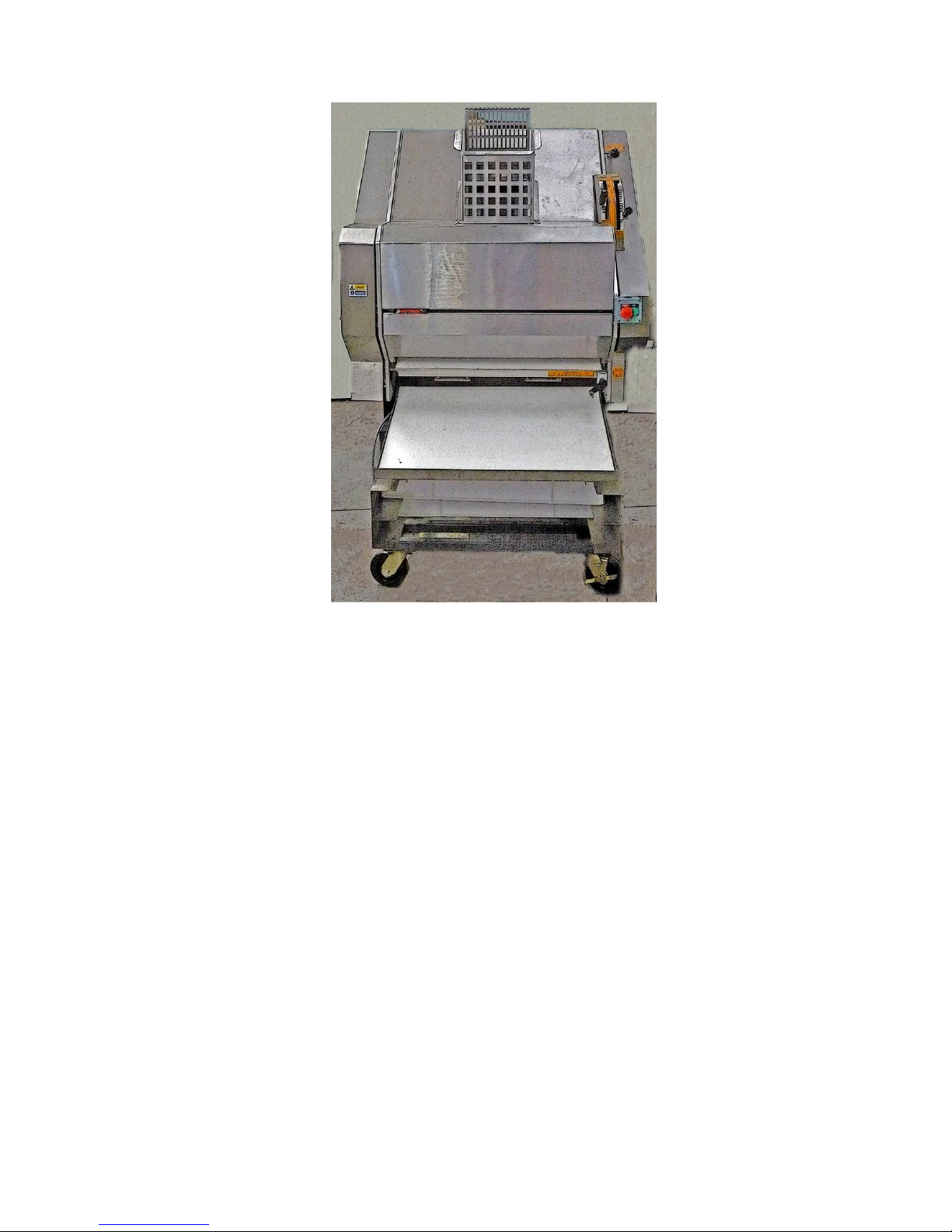
1.0 INTRODUCTION
MONO’s 105 Moulder combines the capabilities of traditional bread and French stick moulding
machines. Its small footprint and simple controls are of particular benefit in small bakeries.
The 105 Moulder will process up to 900 dough pieces an hour.
2.0 OVERALL DIMENSIONS
Height: 1825mm.
Depth: 1205mm.
Width: 1020mm.
Flexi moulder RevA19 10-01-19
6

The supply to this machine must be protected by a
30mA RCD
3.0 SPECIFICATIONS
Total power: 0.75kW three phase
Capacity: Up to 900 dough pieces processed every hour, between 250g (9oz) and 0.9kg (2lb)
in weight and between 125mm (5”) and 760mm (30”)
Weight: 430kg
Noise level: Less than 85dB.
Flexi moulder RevA19 10-01-19
7

4.0 SAFETY
1 Never use a machine in a faulty condition and always report damage.
2 No one under 16 may operate this machine.
3 No one under 18 may clean this machine.
4 Only trained and authorised persons may remove any part that requires a tool to do so.
5 Always ensure hands are dry before touching any electrical appliance (including cable and
plug).
6 All operatives must be fully trained.
7 People undergoing training on the machine must be under direct supervision of a trainer.
8 Do not operate with any panels removed.
9 All guards must be fixed in place with bolts or screws unless protected by a
safety switch.
10 No loose clothing or jewellery to be worn while operating the machine.
11 Switch off power at the mains isolate switch or isolate at the main control box
12 The Bakery Manager or the bakery Supervisor must carry out daily safety checks.
13 Warning: Do not attempt to scrape moulding belts when moulder is running.
14 Any internal maintenance must be by fully trained maintenance personnel.
WARNING: Hand or bodily contact with moving belt surfaces may cause friction burns to skin.
This situation need not occur to successfully operate moulder
Flexi moulder RevA19 10-01-19
8

5.0 INSTALLATION
1 Ensure machine is standing on a solid level floor. Lock the two front castors into place.
2 Check machine after installation to ensure drive motor rotation is in the direction of arrow.
This should be done with drive V-belt removed. If motor rotation is incorrect, change round
any two of the three phase carrying wires. Drive motor should be travelling in an anticlockwise direction.
Flexi moulder RevA19 10-01-19
9

To stop the moulder in an emergency
EMERGENCY STOP BUTTON
6.0
ISOLATION
switch off at the main isolator,
or use the emergency stop button on the front of the machine
,
Flexi moulder RevA19 10-01-19
(TWIST TO RELEASE)
10

SIDE DOOR
LARGE FRONT SHEET
SMALL FRONT SHEET
7.0 CLEANING
DAILY CLEANING INSTRUCTIONS
NOTE! - USE PLASTIC SCRAPERS TO REMOVE SUBSTANTIAL DOUGH PIECES PRIOR TO
CLEANING.
1. Isolate the mains supply.
2. Brush infeed hopper area.
3. Pull out and down, large hopper area sheeting to expose rollers.
INFEED HOPPER
REAR DOOR
(BOTH SIDES)
Flexi moulder RevA19 10-01-19
11

4. Set sheeting gap to the widest mark and brush out residue from the area, using a plastic
scrapper on the rollers if required.
5. Clean any residue that has been trapped at the bottom of the belt.
Scrape exposed surface of the dough-moulding belt with plastic scraper.
6. Close cover and then remove bottom cover by lifting up slightly and lowering down.
7. Brush/vacuum the area and close cover.
Flexi moulder RevA19 10-01-19
12

CLOSED
OPEN
PIN
SLOT
To refit scraper.
CLIP
SCRAPER REMOVAL
To remove scraper.
Slide clips sideways and drop bar down
to disengage (one each side).
Feed under chute and remove.
Feed scraper into position under
chute and lift locating slot on to pin.
Slide clip over protruding bolt to hold
in position. Both sides.
Flexi moulder RevA19 10-01-19
13

LIFT
CURLING CHAIN CLEANING
1. Remove scraper as previous section.
2. Lift black knob on right and slide square shaft to the left while lifting out of location.
3. Place bar diagonally and work out through the top of the machine after unclipping
opposite end of chain at the rear.
Lift clamps/chain off top bar and remove curling chain
4. Clean and replace chain by dropping down conveyor from the back and clipping in
place at the front. (Reverse of removal).
Flexi moulder RevA19 10-01-19
14

A
B
PRESSURE BOARD
Pressure Board Removal
SET TO 400
1. Fully lower the rear-moulding belt using lever (A) and fully lower the pressure board
by adjusting handle (B) to setting “400” on the counter. Open rear door.
2. Remove the pressure board by gripping the handle provided,
and then lift up and out .
3. Wash dough contact surfaces of the pressure board and side guides with
disinfecting solution and hot water. Dry with cloth.
4. Remove any dough from the bottom belt with a plastic scraper.
5. Replace the pressure board, making sure the hooks on the board are fully engaged.
Close the rear door firmly to make the interlock connection.
REAR
BELT
PRESSURE
BOARD
HANDLE
Flexi moulder RevA19 10-01-19
15

OFF TAKE TRAY
This should be scraped clean with a plastic scraper.
OFF TAKE TRAY
• Brush down all external surfaces of the machine including the stand.
• Sweep under machine to remove all debris from the floor.
• Spot clean with cloth dampened, disinfecting solution and hot water, paying particular
attention to handles, levers and controls.
Flexi moulder RevA19 10-01-19
16

WEEKLY CLEANING INSTRUCTIONS
AS DAILY INSTRUCTIONS AND ALSO:
1. Disconnect power (mains plug).
2. Pull machine away from obstructions.
3 Wipe the stand with a cloth dampened with disinfecting solution and hot water.
4 Scrape and scrub the wheels on the machine.
5 Wipe down all internal surfaces with disinfecting solution and hot water.
Dry with a cloth.
Flexi moulder RevA19 10-01-19
17
8.0 OPERATING INFORMATION
1 The Moulder should be used on a level floor for the best results.
2 All control levers, handles, etc are best adjusted when moulder is running, although they
can be adjusted with the machine stationary.
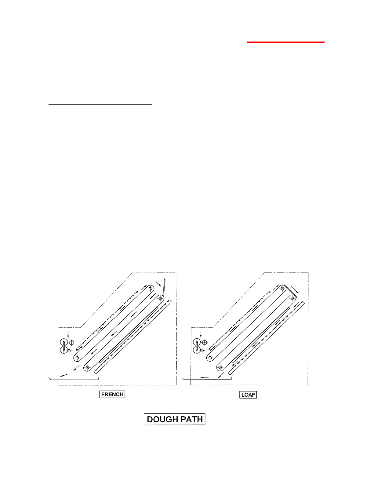
Machine cycle information.
1 The moulding elements consist of two dough guides, two differential sheeting
rollers, a guide roller, a stripper roller, a removable curling chain, two endless
polyurethane belts rotating in the same direction, a two position deflector, a
pressure board, a pair of dough guides and an offtake tray.
2 Dough is delivered from the prover conveyor. The dough is then sheeted through
the two differential rollers into a pancake shape.
3 The dough piece is taken off the rollers by means of a stripper roller and guided
by the remaining roller onto the endless polyurethane belt. Upon making contact
with the belt the dough piece is immediately pressurised by the curling chain mat.
The light pressure produced by the chain causes the dough piece to roll over on
its self and produce a sausage shape.
4 At this stage in the moulding process the dough path can be selected, via pushrod
to be further processed either between front and rear belts or between the rear
belt and pressure board.
5 Both of the moulding routes chosen will deposit the finished dough piece onto an
offtake tray.
Flexi moulder RevA19 10-01-19
18

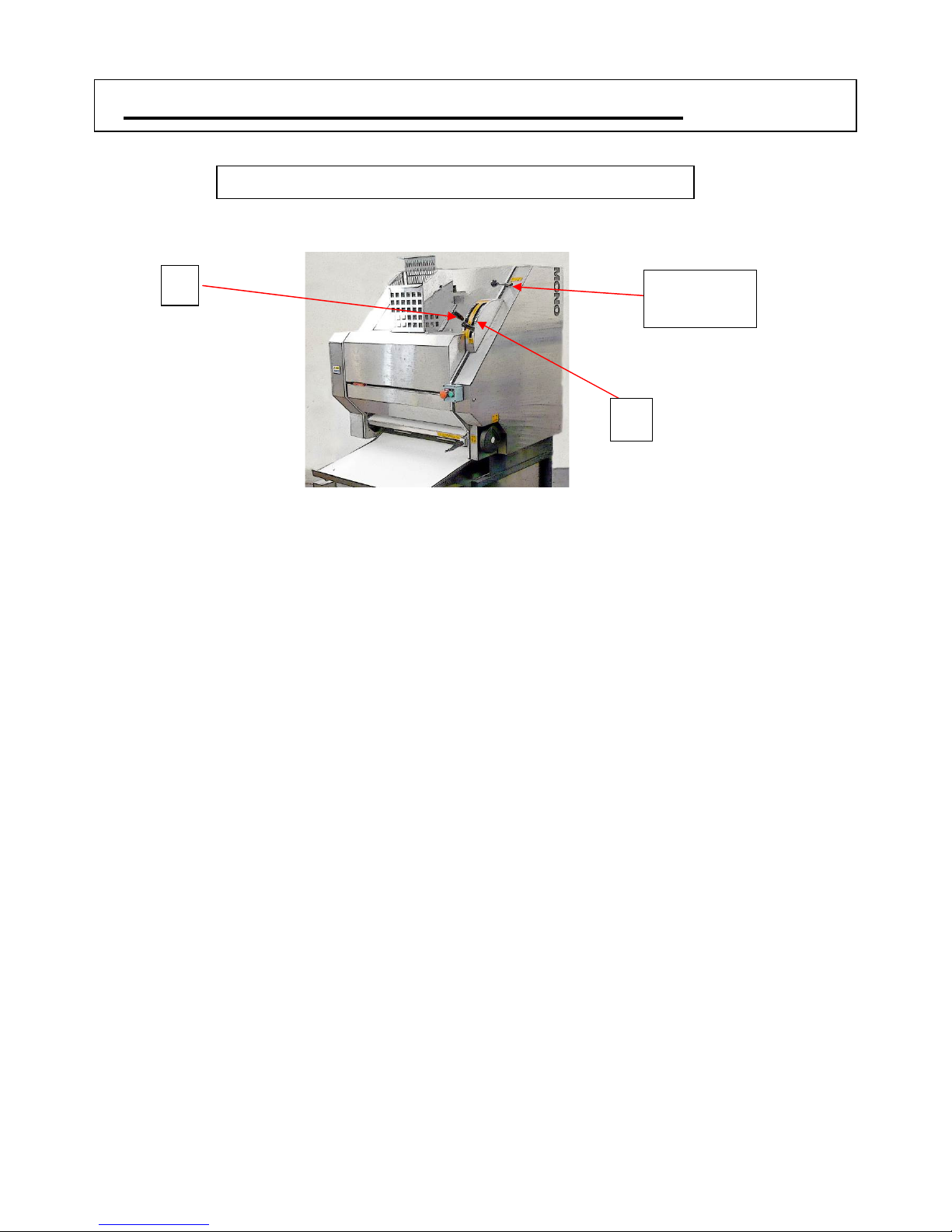
9.0 OPERATING INSTRUCTIONS
E A
STOP/START BUTTONS
B
Ensure the moulder is set up and adequate tins and trays
are available before starting.
D
C
All control levers, handles, etc are best adjusted when moulder is
running, although they can be adjusted with the machine stationary.
Flexi moulder RevA19 10-01-19
19
D
FRENCH STICK AND PETIT PAN PRODUCTS.
E
1 Set lever “A” to control the length of the dough piece required.
2 Adjust “E” to open or close the sheeting gap of the two infeed rollers.
• Control settings will vary according to user, dough mixes, product, machine
• It is advisable for the Bakery Manager to inform staff of settings required for all
Push in pushrod “D” until it engages in locating plate.
PUSHROD
A
construction etc, and are best established by the user.
French range once established. This will result in consistent product, assuming
dough condition is constant.
Flexi moulder RevA19 10-01-19
20

D
TIN BREAD & BLOOMERS.
Pull out pushrod “D” until it engages in locating plate.
1 Position control lever “A” to position 0 – this ensures the correct transfer of the dough
piece after curling and correct discharge of product onto the return conveyor.
2 Adjust handle “E” for the infeed sheeting gap.
E
Scale to show distance
between dough guides
When using hand wheel “C”
3 Adjust handle “B” for the pressure board.
Anti-clockwise will mean the numbers on the digital counter will increase and therefore the
pressure on the dough will decrease. Clockwise will be the opposite. The number on the
digital counter should be noted so it can be reproduced at a later date.
4 Adjust hand wheel “C” to control the length of the loaf.
Hand wheel simultaneously positions the dough side guides equally about the centreline of
the moulder. The distance between the dough guides is indicated by the metal pointer and
the scale
5 After moulding, the dough piece should be transferred from the offtake to a waiting tray.
B
PUSHROD
A
C
Flexi moulder RevA19 10-01-19
21

10.0 MAINTENANCE
1 Refer to cleaning instructions.
2 Maintenance other than cleaning must be carried out by trained maintenance personnel.
3 It is recommended that the bearings, chain, motor, etc. be greased every six months
4 If a belt is tracking to the left or the right. Call in maintenance contractor immediately
before any permanent damage can occur.
MAINTENANCE ENGINEER NOTES
Moulding belts should be no tighter than necessary to eliminate slippage.
Over tensioning can lead to belt and/or bearing failure.
The belt should be adjusted by means of the adjustment tensioning screws (shown below).
The belts should run with equal clearance between its edges and the unit side frames. If
one edge of the belt is tighter than the other, it will tend to run towards the slack side. This
tracking defect can be eliminated by individual adjustment of the tensioning screws.
Caution
Adjustment screws should not be continually tightened (this will cause bearing failure or the
moulding belt to stretch and break). It may be that one side is too tight so should be eased
off a little.
Bearings and bearing grub screws (2 per bearing) should also be checked as a seized
bearing may be the cause of the moulding belt needing adjustment.
If a bearing is replaced, the grub screws should be tightened and liquid thread lock applied.
(On later models the grub screws should also be aligned with dimples in the roller shaft).
Flexi moulder RevA19 10-01-19
ADJUSTMENT TENSIONING
SCREWS
(one side shown.)
22

11.0 TROUBLESHOOTING
MONO
• The final dough temperature, after mixing, should not exceed the ideal.
(typically 25 - 26 º C).
• A dough conditioner containing a good relaxant is required.
• French dough should be soft but not sticky.
• Curling chain should be kept clean.
12.0 SERVICE AND SPARES
If a fault arises, please do not hesitate to contact the
Customer Service Department, quoting the machine serial number
on the silver information plate of the machine and on the front cover of this manual
Swansea West Industrial Estate
email:spares@monoequip.com
Web site:www.monoequip.com
Spares Tel. +44(0)1792 564039
Main Tel. +44(0)1792 561234
Fax. 01792 561016
Queensway
Swansea.
SA5 4EB
UK
Flexi moulder RevA19 10-01-19
23

UNDER
“V” BELT AND DRIVE INFORMATION
DUE TO CONTINUAL IMPROVEMENTS
METALWORK MAY BE SLIGHTLY
DIFFERENT ON THE MODEL YOU HAVE
A900-09-108
Main Pulley
A900-06-259
Bearing
A900-06-242
Bearing
A900-06-227
Bearing
A900-06-259
Bearing
A900-06-259
Bearing
A900-09-105
Motor drive Pulley
Flexi moulder RevA19 10-01-19
A900-21-109
Main drive V belt
24

MOULDING BELT DRIVE INFORMATION
PART NO
.
UNDER
UNDER
UNDER
A900
-09-
104
A900
-06-
259
A900
-09-
098
A900
-06-
227
UNDER
A900-09-097
24T PULLEY
A900-06-259
BEARING
30T PULLEY
BEARING
PULLEY 48T A900-09-093
34T A900-09-094
28T A900-09-095
26T A900-09-096
BELT -- DOUBLE SIDED LARGE A900-21-092
-- TIMING BELT A900-21-093
A900-06-259
BEARING
A900-09-096
26T PULLEY
A900-21-092
TIMING BELT
A900-06-242
BEARING
A900-09-104
40T PULLEY
A900-09-095
28T PULLEY
A900-21-093
TIMING BELT
40T PULLEY
A900-09-094
34T PULLEY
A900-09-096
26T PULLEY
A900-06-227
BEARING
BEARING
A900-06-259
BEARING
A900-09-093
48T PULLEY
Flexi moulder RevA19 10-01-19
25
13.0 MOULDER ELECTRICAL
INFORMATION
Flexi moulder RevA19 10-01-19
26

Flexi moulder RevA19 10-01-19
27

Flexi moulder RevA19 10-01-19
28

Flexi moulder RevA19 10-01-19
29

DISPOSAL
MONO Equipment
Queensway,
Swansea West Industrial Park,
Swansea,
SA5 4EB
UK
Tel. +44(0)1792 561234
Fax. 01792 561016
Spares Tel. +44(0)1792 564039
Email:mono@monoequip.com
www.monoequip.com
As it is our policy to improve our machines continuously, we reserve the right
to change specifications without prior notice.
CARE SHOULD BE TAKEN WHEN THE MACHINE COMES TO THE END OF ITS WORKING LIFE. ALL
PARTS SHOULD BE DISPOSED OF IN THE APPROPRIATE PLACE, EITHER RECYCLING OR OTHER
MEANS AS THE LAW PERMITS AT THE TIME.
Flexi moulder RevA19 10-01-19
30
 Loading...