

Page 1

English
Original Instructions
Installation, Operation
and Maintenance Instructions
MM / ML Range
OMMP/014/01
Rev 5, December 2009
Page 2

Spares & Service Contact Details
Mono UK
Spares +44 (0)161 214 2380 (direct line 8.15 am – 5.00 pm)
E-mail [email protected]
Service +44 (0)161 214 2390 (direct line 8.15 am – 5.00 pm)
E-mail [email protected]
Service +44 (0)161 339 9000 (24 hrs)
Mono Australia
Telephone Facsimile
Melbourne (03) 9580 5211 (03) 9580 9036
Sydney (02) 9521 5611 (02) 9542 3649
Brisbane (07) 3350 4582 (07) 3350 3750
Adelaide (08) 8447 8333 (08) 8447 8373
Perth (08) 9479 0444 (08) 9479 0400
Darwin (08) 8984 3099 (08) 8947 0540
Tasmania 0417 345 814 (03) 6330 2051
E-mail [email protected]
Mono New Zealand
Spares & Service +64 (0)9 829 0333
E-mail [email protected]
Monoflo USA
Spares & Service +1 713 466 7999
E-mail [email protected]
Monoflo South America
Spares & Service +54 4296 8997 +54 4284 0323
E-mail [email protected]
Mono China
Beijing +86 (0) 10 6461 1115 +86 (0) 10 8486 8481
Shanghai +86 (0) 21 5915 7168 +86 (0) 21 5915 6863
E-mail [email protected]
Spares & Service
Issued – April 2008
Telephone Facsimile
Page 3

ATEX Warning Statements
PUMPS AND PUMP UNITS
Where a pump or pump unit is to be installed in a
potentially explosive atmosphere ensure that this has
been specified at the time of purchase and that the
equipment has been supplied accordingly and
displays an ATEX nameplate or is supplied with a
certificate of conformity. If there is any doubt as to the
suitability of the equipment please contact Mono
Pumps Limited before commencing with installation
and commissioning.
Process liquids or fluids should be kept within
specified temperature limits otherwise the surface of
pump or system components may become an ignition
source due to temperature rises. Where the process
liquid temperature is less that 90ºC the maximum
surface temperature will not exceed 90ºC provided
the pump is installed, operated and maintained in
accordance with this manual. Where the process fluid
temperature exceeds 90ºC the maximum surface
temperature will be equal to the maximum process
fluid temperature.
Cavities that could allow the accumulation of
explosive gases, such as under guards, should where
possible, be designed out of the system. Where this is
not possible they should be fully purged before any
work is carried out on the pump or system.
Electrical installation and maintenance work should
only be carried out by suitably qualified and
competent persons and must be in accordance with
relevant electrical regulations.
All electrical equipment, including control and safety
devices, should be suitably rated for the environment
in to which they are installed.
Where there may be a risk of an accumulation of
explosive gases or dust non-sparking tools should be
used for installation and maintenance.
In addition to causing permanent damage to the
stator, dry running of the pump could generate a rapid
rise in the temperature of the stator tube or barrel,
which could become an ignition source. It is therefore
essential that a dry run protection device be fitted.
This must shut the pump down immediately should a
dry run situation occur. Details of suitable devices are
available from Mono Pumps Limited.
To minimise the risk of sparking or temperature rises
due to mechanical or electrical overload the following
control and safety devices should be fitted in addition
to a dry run protection system. A pressure relief
system whereby the pump can not generate
pressures in excess of the maximum rated pressure
or an over pressure device which should shut the
pump down when the maximum discharge pressure is
exceeded. A control system that will shut the pump
down if the motor current or temperature exceed
specified limits. An isolator switch that will disconnect
all electrical supply to the motor and ancillary
electrical equipment and be capable of being locked
in the off position. All control and safety devices
should be fitted, operated and maintained in
accordance with the manufacturer’s instructions. All
valves on the system should be open when the pump
is started otherwise serious mechanical overload and
failure may result.
It is important that the pump rotates in the direction
indicated on the nameplate. This must be checked on
installation and commissioning and after any
maintenance has been carried out. Failure to observe
this may lead to dry running or mechanical or
electrical overload.
ATEX - Page 1 of 2
Issued – February 2004
Reference - OMMP/028/01/R1
Page 4

ATEX Warning Statements
When fitting drives, couplings, belts, pulleys and
guards to a pump or pump unit it is essential that
these are correctly fitted, aligned and adjusted in
accordance with the manufacturer’s instructions.
Failure to do so may result in sparking due to
unintended mechanical contact or temperature rises
due to mechanical or electrical overload or slipping of
drive belts. Regular inspection of these parts must be
carried out to ensure they are in good condition and
replacement of any suspect part must be carried out
immediately.
Mechanical seals should be suitably rated for the
environment. The seal and any associated
equipment, such as a flushing system, must be
installed, operated and maintained in accordance with
the manufacturer’s instructions.
The use of replacement parts that are not
manufactured by or approved by Mono Pumps Limited
may affect the safe operation of the pump and it may
therefore become a safety hazard to both operators
and other equipment. In these circumstances the
Declaration provided will become invalid. The
guarantee referenced on the Terms and Conditions of
Sale will also be invalidated.
Where a packed gland seal is fitted this must be
correctly fitted and adjusted. This type of seal relies
on the process liquid to cool the shaft and packing
rings so a constant drip of liquid from the gland
section is required. Where this is undesirable an
alternative seal type should be fitted.
Failure to operate or maintain the pump and ancillary
equipment in line with the manufacturer’s instructions
may lead to premature and potentially dangerous
failure of components. Regular inspection, and where
necessary replacement, of bearings and lubrication is
essential.
The pump and its components have been designed to
ensure safe operation within the guidelines covered
by legislation. Accordingly Mono Pumps Limited have
declared the machine safe to use for the duty
specified as defined by the Declaration of
Incorporation or Conformity that is issued with this
instruction manual.
ATEX - Page 2 of 2
Issued – February 2004
Reference - OMMP/028/01/R1
Page 5

Index
SECTION 1 INSTALLATION
START-UP PROCEDURE
ASSEMBLY AND DISMANTLING ADVICE
SECTION 2 FAULT FINDING
SECTION 3 DRAWING REFERENCE NUMBERS
PUMP CODING SHEET
SECTION 4 DISMANTLING AND ASSEMBLY DIAGRAMS
EXPLODED VIEWS
SECTION 5 TORQUE TIGHTENING FIGURES
EC Declaration
The following harmonised standards are applicable: BS EN 809,
as defined by Machinery Directive 2006/42/EC.
EC Declaration of Incorporation
This declaration is only valid when partly completed
machinery has been supplied.
In this case, the machinery meets the requirements of the
said directive and is intended for incorporation into other
machinery or for assembly with other machinery in order
to constitute relevant machinery as defined by the said
directive including any amendments, which are valid at the
time of supply.
IMPORTANT
This machinery must not be put into service until the
relevant machinery into which it is to be incorporated has
been declared in conformity to the said directive.
This declaration is only valid when the machinery has
been installed, operated and maintained in accordance
with these instructions and safety guidelines contained
within as well as instructions supplied for equipment
assembled with or intended for use with this equipment.
BS EN ISO 12100 Parts 1 & 2
EC Declaration of Conformity
This declaration is not valid for partly completed machinery
has been
In this case the machinery meets the requirements of the
said directive including any amendments which are valid at
the time of supply.
We further declare that, where applicable, said machinery also
meets the requirements of:
The EMC Directive 2004/108/EC
The Low Voltage Directive 2006 /95/E
The Pressure Equipment Directive 97/23/EC
The Outdoor Noise Directive 2005/88/EC
The Drinking Water Directive 99/83/EC
supplied.
IMPORTANT
This declaration is only valid when the machinery has been
installed, operated and maintained in accordance with these
instructions and safety guidelines contained within as well
as instructions supplied for equipment assembled with or
intended for use with this equipment.
Index
Issued – December 2009
Mr C. Q. Griffiths - Engineering Services Manager.
for Mono Pumps Limited, Martin Street, Audenshaw,
Manchester England, M34 5JA
Page 6
Installation, Operation & Maintenance Instructions
INSTALLATION
1.1 INSTALLATION AND SAFETY
RECOMMENDATIONS
In common with other items of process plant a pump
must be installed correctly to ensure satisfactory and
safe operation. The pump must also be maintained
to a suitable standard. Following these
recommendations will ensure that the safety of
personnel and satisfactory operation of the pump is
achieved.
1.2.1. GENERAL
When handling harmful or objectionable materials,
adequate ventilation must be provided in order to
disperse dangerous concentrations of vapours. It is
recommended that wherever possible, Mono pumps
should be installed with provision for adequate
lighting, thus ensuring that effective maintenance
can be carried out in satisfactory conditions. With
certain product materials, a hosing down facility with
adequate draining will simplify maintenance and
prolong the life of pump components.
Pumps operating on high temperature duties
should be allowed to cool sufficiently before any
maintenance is carried out.
1.2.2. SYSTEM DESIGN & INSTALLATION
At the system design stage, consideration must be
given to provision of filler plugs, and the
of non-return and/or isolating valves. Pumps cannot
be reliably used as non-return valves. Pumps in
parallel and those with high static discharge head
must be fitted with non-return valves.
The pumps must also be protected by suitable
devices against over pressure and dry running.
i. HORIZONTAL MOUNTING
All ranges excluding P Range Mono pumps are
normally installed in a horizontal position with
baseplates mounted on a flat surface, grouted in
and bolted, thus ensuring firm fixing and a reduction
in noise and vibration.
The unit should be checked after bolting down to
ensure that the alignment of the pump to its prime
mover is correct.
ii. VERTICAL MOUNTING
P Range Pumps Only
installation
Normally 'P' range pumps will be designed with a
sole plate that will be bolted
framework.
If the pump is to be mounted in any way other than
described above, confirmation of the installation
must be agreed with Mono Pumps Limited. All the
pipework should be independently supported.
1.3.1 HANDLING
During installation and maintenance, attention must
be paid to the safe handling of all items. Where a
pump or its components weigh in excess of 20 kg
(45lb) it is recommended that suitable lifting tackle
should be used to ensure that personal injury or
damage to components does not occur.
For safe handling of both bareshaft pumps and
pump units (pump/ gearbox/motor etc.) slings should
be used. The position of the slings will depend upon
the specific pump/unit construction and should be
carried out by personnel with the relevant
experience to ensure that the pump is not damaged
and injury to personnel does not occur.
If eyebolts do exist then these should only be used
for lifting the individual com
are supplied.
1.3.2 STORAGE AND INFREQUENT OPERATION
The situation where a pump is used infrequently is
also covered by the instructions in this section.
SHORT TERM STORAGE
Where a pump has to be stored for 6 months or
less then the following steps are advised:-
1. Store pump inside wherever possible or if this is not
feasible then provide protective covering. Do not
allow moisture to collect around the pump.
2. Remove the drain plug, if fitted. Any inspection
plates fitted should also be removed to ensure that
the suction housing can drain and dry completely.
3. Loosen the packed gland and inject sufficient grease
into the stuffing box. Tighten the gland nut hand
tight. If a water flush system is to be used do not
grease, a small amount of light oil is recommended
for these.
to the customers
ponents for which they
The P range pumps are intended for vertical
installation. Care must be taken when lifting the
pump into the vertical position.
Section 1, Page 1
Issued – October 2009
4. See Manufacturers Instructions for
motor/gearbox/drive instructions for storage
procedures.
Page 7
Installation, Operation & Maintenance Instructions
LONG TERM STORAGE
If the pump is to be kept in storage for more than
six months then in addition to the above the
following procedures should be carried out
regularly (every 2 - 3 weeks if possible):
1. If practicable rotate the pump at least three quarters
of one revolution to avoid the rotor setting in the
stator.
2. Note, however, that the pump is not to be rotated for
more than two revolutions each time because
damage could be caused to the rotor/ stator
elements.
IMMEDIATELY PRIOR TO INSTALLATION AND
STARTING
Before installing the pump please ensure that all
plugs and inspection plates are replaced and
that excess grease/oil is removed from the
stuffing box.
1.4 ELECTRICAL
Electrical connection should only be made using
equipment suitable for both rating and environment.
Where any doubts exist regarding the suitability of
equipment, Mono Pumps Limited, should be
consulted before proceeding. Normally the Mono
pump should be installed with starting equipment
arranged to give direct on line starting.
Earthing points will be provided on electric drives (if
supplied) and it is essential that these are correctly
connected. When the motor is being wired and
checked for rotation, the start/stop sequence must
be instantaneous to prevent dry running (see 2) or
pressurising upstream equipment. (Check direction
arrow on pump nameplate). The electrical
installation should include appropriate isolating
equipment to ensure that the pump unit is safe to
work on.
1.5 PRESSURE RELIEF VALVES AND NON-RETURN
VALVES
1. It is recommended that a suitable safety device is
installed on the discharge side of the pump to
prevent over-pressurisation of the system.
2. It is also recommended that a non-return valve is
installed on the discharge side of the pump to
prevent reverse flow through the system.
When both are installed it is advised that the relief
valve is positioned closer to the pump than the nonreturn valve.
IMPORTANT
The pump must never run against a closed inlet
or outlet valve, as this could
mechanical failure.
1.6 GENERAL SAFETY
GREAT CARE MUST BE TAKEN TO PROTECT
ALL ELECTRICAL EQUIPMENT FROM
SPLASHING WHEN HOSING DOWN. WHERE
MONO PUMPS LIMITED HAVE SUPPLIED A
BARESHAFT PUMP THE ONUS IS ON THE USER
TO FIT ADEQUATE GUARDS IN COMPLIANCE
WITH THE REQUIREMENTS OF THE RELEVANT
REGULATIONS.
All nuts and bolts, securing flanges and base
mounting fixtures must be checked for tightness
before operation. To eliminate vibration, the pump
must be correctly aligned with the drive unit, and all
guards must be securely fixed in position. When
commissioning the plant, all joints in the system
must be checked thoroughly for leakage.
If, when starting, the pump does not appear to
operate correctly (see 2), the plant must be shut
down immediately and the cause of the malfunction
established before operations are recommenced. It
is recommended that depending upon plant system
operation, either a combined
gauge, or a vacuum gauge only be fitted to the
pump inlet port, and a pressure gauge fitted to the
outlet port, these will then continuously monitor the
pump operating conditions.
from the ECHA SVHC Candidates List
(REACH - Regulation (EC) No. 1907/2006)
1.7 DUTY CONDITIONS
Pumps should only be installed on duties for which
Mono Pumps Limited have specified the materials of
construction, flow rates, pressure, temperature,
speed etc. Where dangerous materials are to be
pumped, consideration must be given to the safe
discharge from relief valves, gland drains etc.
IF THE DUTY SHOULD BE CHANGED, MONO
PUMPS LIMITED SHOULD BE CONTACTED AND
THEIR RECOMMENDATIONS SOUGHT IN THE
INTEREST OF APPLICATION, SAFETY OF
PLANT, EFFICIENCY AND PUMP LIFE.
result in
vacuum and pressure
May contain substances
Section 1, Page 2
Issued – September 2009
Page 8
Installation, Operation & Maintenance Instructions
2. START-UP PROCEDURE
Pumps must be filled with liquid before starting. The
initial filling is not for priming purposes, but to
provide the necessary lubrication of the stator until
the pump primes itself. When the pump is stopped,
sufficient liquid will normally be trapped in the
rotor/stator assembly to provide lubrication upon restarting.
If, however, the pump has been left standing for an
appreciable time, moved to a new location, or has
been dismantled and re-assembled, it must be
refilled with liquid and given a few turns before
starting. The pump is normally somewhat stiff to
turn by hand owing to the close rotor/stator fit.
However, this stiffness disappears when the pump is
running normally against pressure.
2.1 DRY RUNNING
NEVER RUN THE PUMP IN A DRY CONDITION
EVEN FOR A FEW REVOLUTIONS OR THE
STATOR WILL BE DAMAGED IMMEDIATELY.
CONTINUAL DRY RUNNING COULD PRODUCE
SOME HARMFUL OR DAMAGING EFFECTS.
2.2 PUMP ROTATION DETAILS
PUMP RANGE BI-DIRECTIONAL COMMENT
E
Monobloc B Yes
Merlin Industrial Yes
Merlin Widethroat No
Grout Injection No **
CP0025,CP0800,CP1600 No *
* Clockwise when viewed from drive end.
** Anti-clockwise when viewed from drive end.
†
Anti-clockwise gives inlet at drive end.
Yes
seYLS ,S
seYFL
No
No
oNP
DIRECTIONS OF ROTATION
BEFORE THE DIRECTION OF ROTATION IS
CHANGED, MONO PUMPS LIMITED MUST BE
CONSULTED SO THAT THE SUITABILITY OF
THE PUMP CAN BE CONFIRMED WHEN
OPERATING ON THE NEW DUTY.
2.3.1. GLAND PACKING
Where a pump is supplied fitted with gland packing
(manufactured from a non-asbestos material), the
gland will require adjustment during the initial
running in period. Newly packed glands must be
allowed to run-in with only finger tight compression
on the gland follower nuts. This should continue for
about 3 days. The gland follower should be
gradually tightened over the next week to achieve a
leakage rate as shown in the table below. Gland
followers should be adjusted at regular intervals to
maintain the recommended leakage flow rate.
Under normal working conditions a slight drip from
the gland under pressure assists in cooling and
lubricating the packing. A correctly adjusted
gland will always have small leakage of fluid.
Typical Leakage Rates from Packed Glands
Up to 50mm shaft diameter 2 drops per minute
50 … 75mm shaft diameter 3 drops per minute
75 … 100mm shaft diam
eter
4 drops per minute
100 … 125mm shaft diameter 5 drops per minute
125 … 160mm shaft diameter 6 drops per minute
A gland drip is, however, undesirable when handling
corrosive, degreasing, or abrasive materials. Under
these conditions the gland must be tightened the
minimum amount whilst the pump is running to
†
†
†
†
†
**W
**
*oNLM MM
**oNSM
*G
*oNBS/BC
**oNrecalP
*
**oN1100PC
ensure satisfactory sealing when under pressure, or
to stop entry of air when under suction conditions.
The gland leakage of toxic, corrosive or hazardous
liquids can cause problems of compatibility with the
pumps materials of construction.
Provision of a gland drain should be considered,
especially for the leakage of hazardous products.
CARE IS REQUIRED WHEN ADJUSTING THE
GLAND WHILST PUMP IS RUNNING.
2.3.2 MECHANICAL SEALS - ALL PUMPS
When a mechanical seal is fitted to the pump it may
be necessary to provide a barrier fluid to some part
of the seal. This should be provided in line with the
seal manufacturers instructions.
2.4. GUARDS
In the interests of safety, and in accordance with the
U.K. Health and Safety at Work Act 1974, all guards
must be replaced after necessary adjustments have
been made to the pump.
Section 1, Page 3
Issued – December 2002
Page 9

Installation, Operation & Maintenance Instructions
2.5 WARNING/CONTROL DEVICE
Prior to operating the pump, if any warning or control
devices are fitted these must be set in accordance
with their specific instructions.
2.6 PUMP OPERATING TEMPERATURE
The range of temperatures the pump surfaces will
develop is dependent upon factors such as product
temperature and ambient temperature of the
installation. There may be instances where the
external pump surface can exceed 50oC.
In these instances, personnel must be made aware
of this and suitable warnings/guarding used.
2.7 NOISE LEVELS
1. The sound pressure level should not exceed 85dB
at one metre distance from the pump.
2. This is based on a typical installation and does not
necessarily include noise from other sources or
any contribution from building reverberation or
installation pipework
BP LC2 / Mobilgrease XHP 222 or their equivalent
must be used for replenishment.
2.9 PUMP UNITS
Where a pump unit is dismantled and re-assembled,
consideration must be given to ensure that where
appropriate the following steps are covered.
1. Correct alignment of pump/gearbox
2. Use of appropriate couplings & bushes
3. Use of appropriate belts & pulleys correctly
tensioned.
2.10 CLEANING PRIOR TO OPERATION
i. Non Food Use
During the commissioning of a new pump or
recommissioning of an overhauled pump, it is
advisable to clean the pump prior to the initial
operation of the pump in the process.
ii. Food Use
When a pump has been supplied for a food
application, it is important to ensure that the pump is
clean prior
to initial operation of the pump.
3. It is recommended the actual pump unit noise
levels are ascertained once the unit is installed and
running at duty conditions
2.8 LUBRICATION
Pumps fitted with bearings should be inspected
periodically to see if grease replenishment is
necessary, and if so, grease should be added until
the chambers at the ends of the bearing spacer are
approximately one third full.
Periodic bearing inspection is necessary to maintain
optimum bearing performance. The most expedient
time to inspect is during periods of regular
scheduled equipment downtime - for routine
maintenance or for any
Under tropical or other arduous conditions, however,
a more frequent examination may be necessary. It
is therefore advisable to establish a correct
maintenance schedule or periodic inspection.
other reason.
Therefore, it is important that a clean-in-place
treatment is executed on the pump at the following
times:-
1. When the pump is first commissioned for use.
2. When any spare components are fitted into the
wetted area of the pump.
A recommended CIP procedure is as follows:
This procedure should not be used on the CP
Pump Range. Please consult our application
engineers for a suitable procedure.
Caustic Wash
LQ94 ex Lever Diversey or equivalent
2% concentration
Acid Wash
P3 Horolith 617 ex Henkel
Ecolab or equivalent 1% concentration
Procedure
Section 1, Page 4
Issued – August 2009
1. Caustic wash @ 75°C for 20 mins
2. Water rinse @ 80°C for 20 mins
Page 10
Installation, Operation & Maintenance Instructions
3. Acid wash @ 50°C for 20 mins
4. Water rinse @ 80°C for 20 mins
CIP flow rates (hence pump speeds) should be
maximised to achieve highest level of cleanability.
A C.I.P. liquid velocity of 1.5 to 2.0 m/s is required
for removal of solids and soiling.
Pumps fitted with CIP by pass ports will permit
higher flow rates without the need to increase pump
speed.
The use of neat active caustic
and acid chemicals is not
recommended. Proprietary cleaning
agents should be used in line with manufacturers
instructions.
All seals and gaskets should be
replaced with new if disturbed
during maintenance.
Pump internals should be regularly inspected to
ensure hygienic integrity is maintained, especially
with respect to elastomeric components and seals,
and replaced if necessary.
The four stages constitute one cycle and we
recommend that this cycle is used to clean the pump
before use on food.
Once the pump has been commissioned, the
cleaning process will depend upon the application.
The user must therefore ensure that their cleaning
procedures are suitable for the duty for which the
pump has been purchased.
2.11 WIDETHROAT PUMPS
Specific pumps may have auger feed screws, with
or without a bridge breaker system to feed the
pumping element. If the pump installation requires
that these cannot be enclosed, care must be taken
to ensure personnel cannot gain access whilst the
pump is operating. If this is not possible an
emergency stop device must be fitted nearby.
2.12 EXPLOSIVE PRODUCTS/ HAZARDOUS
ATMOSPHERES
In certain instances the product being pumped may
well be of a hazardous nature.
In these installations consideration must be given to
provide suitable protection and appropriate warnings
to safeguard personnel and plant.
2.13 ACCESS PORTS
Where access ports are fitted then the following
steps must be followed prior to removal:
1. Pump must be shut down and the electrical supply
isolated.
2. Protective clothing should be worn, especially if the
pumped product is obnoxious.
3. Remove access plate with care utilising where
possible drip trays to collect product leakage.
Access ports are included to assist in removing
blockages and to allow a visual check on the
components within the suction chamber.
It is not to be considered as an additional method in
dismantling the pump.
Re-assembly of the plate should be completed using
new gaskets prior to the pump being switched on.
2.14 ADJUSTABLE STATORS
If adjustable stators are fitted then the following
steps must be followed for adjusting the clamping
devices.
The adjustable stator assembly is designed to give
an even compression around the stator
circumference. It is designed to be used when
pump performance reduces through wear to an
unacceptable level, to restore the required flow rate.
The stator compression is increased using the
following steps:-
1. Release the six locking screws half a turn.
2. Tighten the eight clamp screws until adjustment
allowed by releasing the lock screws has been taken
up.
3. Repeat steps 1 and 2 until the pump performance
has been restored to its former level.
NOTE
It is imperative that when adjusting the stator that
only sufficient pressure is placed on the stator to
enable the capacity of the pump to be reinstated.
Over tightening of the stator could easily result in
damage to the driver by overload and so extreme
care must be taken when carrying out these
adjustments.
Section 1, Page 5
Issued – December 2002
Page 11
Installation, Operation & Maintenance Instructions
It is therefore advisable to make the adjustment
while the pump is running and power readings can
be monitored.
REMOVAL OF ADJUSTABLE STATOR
The procedure for removal of an adjustable stator is
the same as that of a standard one, except it is
necessary to remove the clamp plates before the
stator can be twisted off the rotor.
This can be done by undoing the clamp screws;
then releasing the clamp plate by using the locking
screws as jacking screws to remove the clamp
plates.
Re-assembly will be done using the reverse
procedure.
2.15 MAINTENANCE OF WEARING COMPONENTS
2.15.1 ROTOR AND STATOR
The wear rate on these components is dependent
on many factors, such as product abrasivity, speed,
pressure etc.
2.15.4 FLEXISHAFT DRIVE PUMPS
With this design there are no wearing items to
replace in the drive train, however, if during routine
inspection the shaft is visibly damaged / distorted
or the protective coating is damaged, then this item
should be replaced to avoid unexpected
breakdowns.
2.16 MECHANICAL SPEED VARIATORS
Refer to the manufacturers instructions.
These machines require regular maintenance, which
typically includes weekly adjustment through the full
speed range.
3.0 ASSEMBLY AND DISMANTLING
Section 4 contains the steps to dismantle and
re-assemble the pump. All fastenings must be
tightened securely and when identified the
appropriate torque figures should be used.
3.1 USE OF ITEMS NOT APPROVED OR
MANUFACTURED BY MONO PUMPS LIMITED
When pump performance has reduced to an
unacceptable level one or possibly both items will
need replacing.
2.15.2 DRIVE SHAFT - PACKED GLAND
The wear rate of the gland area is dependent on
many factors such as product abrasivity and speed.
Regular gland maintenance will maximise the life of
the shaft. Replacement of both the gland packing
and shaft will be necessary when shaft sealing
becomes difficult to achieve.
2.15.3 COUPLING ROD JOINTS
Regular maintenance and lubrication will maximise
life of the joints.
Replacement of one or both joint assemblies and
possibly the coupling rod may be necessary when
wear is apparent.
It is essential to replace all the joint items with
genuine Mono parts to ensure maximum life.
The pump and its components have been designed
to ensure that the pump will operate safely within the
guidelines covered by the legislation.
As a consequence Mono Pumps Limited have
declared the machine safe to use for the duty
specified as defined by the Declaration of
Incorporation or Conformity that is issued with this
Instruction Manual.
The use of replacement items that are not approved
by or manufactured by Mono Pumps Limited may
affect the safe operation of the pump and it may
therefore become a safety hazard to both operators
and other equipment. In these instances the
Declaration provided will therefore become invalid.
The guarantee referenced in the Terms and
Conditions of Sale will also be invalidated if
replacement items are used that are not approved or
manufactured by Mono Pumps Limited.
DISPOSAL OF WORN COMPONENTS
When replacing wearing parts, please ensure
disposal of used parts is carried out in compliance
with local environmental legislation. Particular care
should be taken when disposing of lubricants.
Section 1, Page 6
Issued – December 2002
Page 12
Installation, Operation & Maintenance Instructions
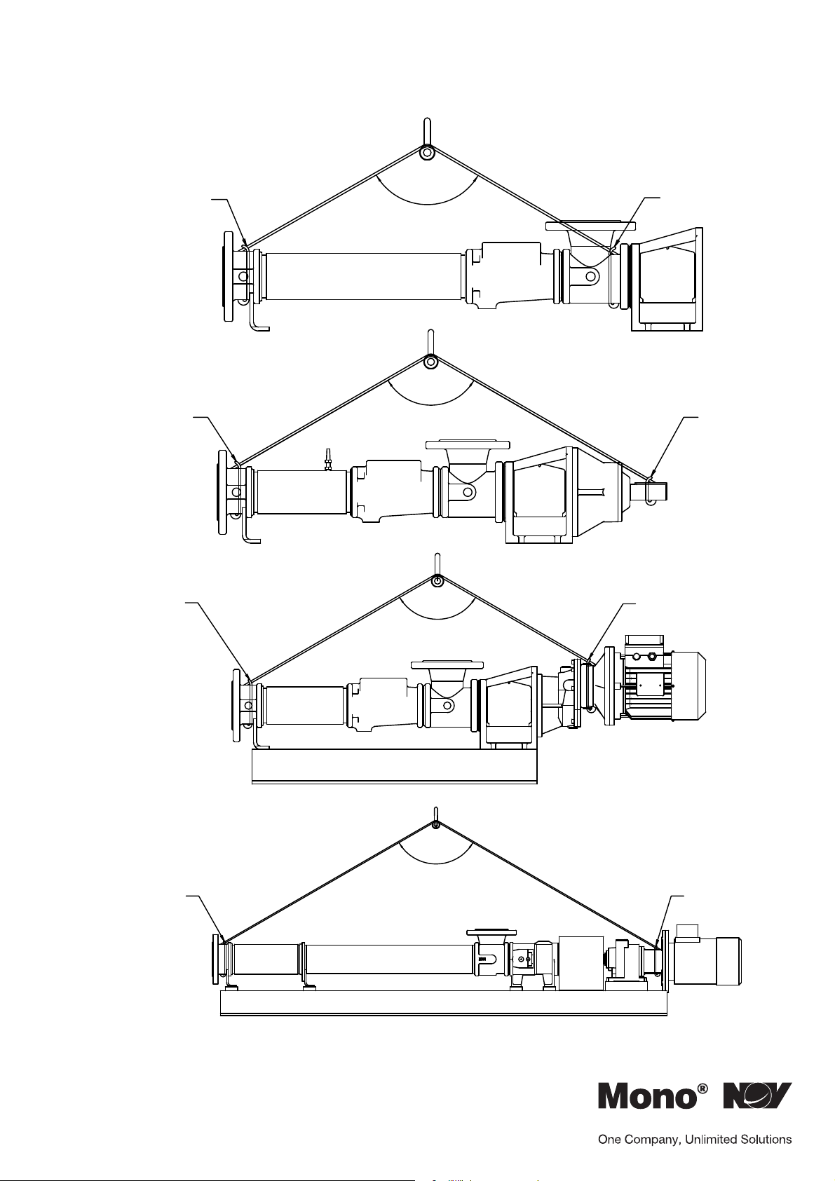
3.2 RECOMMENDED LIFTING POINTS
120°
CHOKE
1
CHOKE
2
MAX
120°
MAX
CHOKE
CHOKE
CHOKE
3
CHOKE
4
120°
MAX
120°
MAX
CHOKE
CHOKE
Section 1, Page 7
Issued – August 2009
Page 13
Installation, Operation & Maintenance Instructions
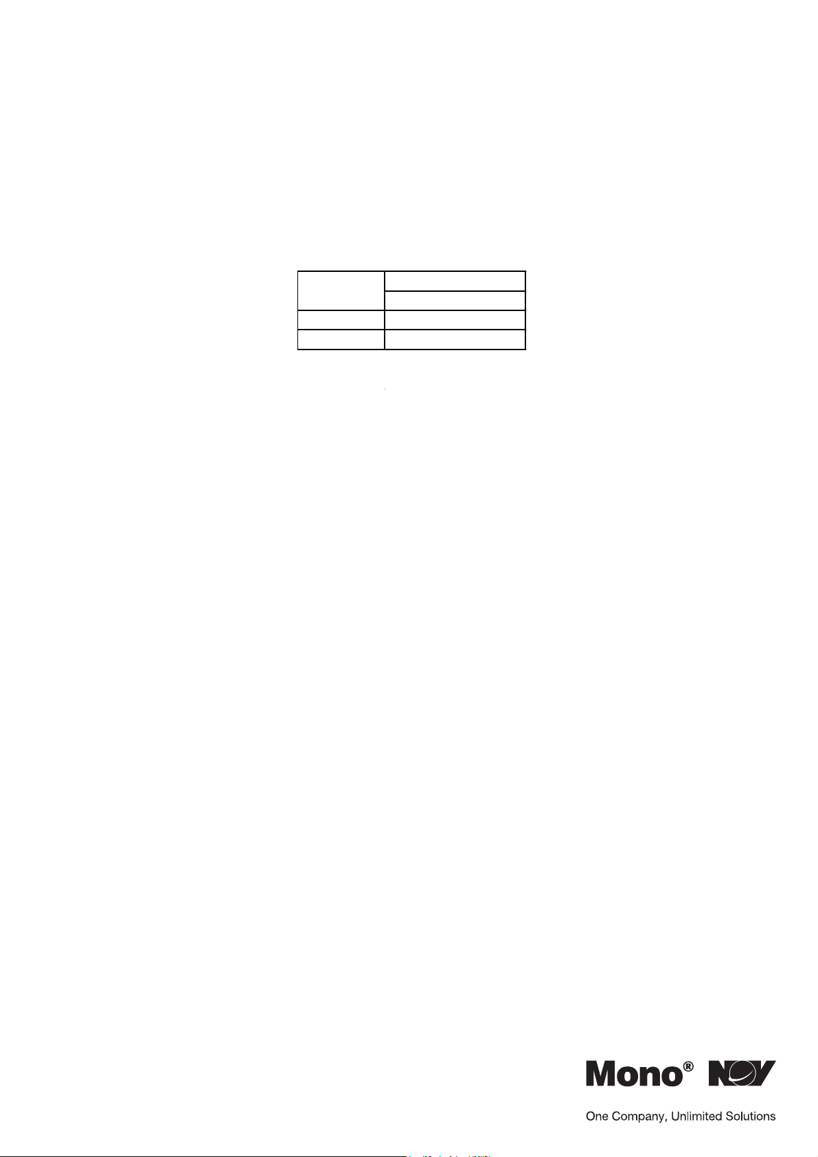
Model
3.3 PUMP AND WEAR PARTS WEIGHTS.
NOTE: Weights are for guidence purpose only. Please refer to the documetation
issued with your pump or spares.
M Range
Pump Weight (kg)
Motorised
MS 16
MM/ML 27
All wear parts are less than 5kg
Section 1, Page 8
Issued – October 2009
Page 14

Diagnostic Chart
1. NO DISCHARGE
2. LOSS OF CAPACITY
3. IRREGULAR DISCHARGE
4. PRIMING LOST AFTER START
5. PUMP STALLS AT START UP
6. PUMP OVERHEATS
7. MOTOR OVERHEATS
8. EXCESSIVE POWER ABSORBED BY PUM P
9. NOISE AND VIBR ATION
10. PUMP ELEMENT WEAR
11. EXCESSIVE GLAND OR SEAL WEAR
12. GLAND LEAKAGE
13. SEIZURE
1. INCORRECT DIRECTION OF ROTATION
2. PUMP UNPRIMED
3. INSUFFICIENT N.P.S.H. AVAILABLE
4. PRODUCT VAPORISING IN SUPPLY LINE
5. AIR ENTERING SUPPLY LINE
6. INSUFFICIEN T HEAD ABOVE SUPPLY VE S SEL OUTLET
7. FOOTVALVE/STRAINER OBSTRUCTED OR BLOCKED
8. PRODUCT VISCOSIT Y ABOVE RATED FIGURE
9. PRODUCT TEMP. ABOVE RATED FI GURE
10. PRODUCT VISCOSIT Y BELOW RATED FIGURE
11. DELIVERY PRESSURE ABOVE RATED FIGURE
12. GLAND OVERTIGHT
13. GLAND UNDERTIGHT
14. GLAND FLUSHING INADEQUATE
15. PUMP SPEED ABOVE RATED FIGURE
16. PUMP SPEED BELOW RATED FIGURE
17. BELT DRIVE SLIPPING
18. COUPLING MISALIGNED
19. INSECURE PUMP/DRIVE MOUNTING
20. SHAFT BEARING WEAR/FAILURE
21. WORN PUMP ELEMENT
22. RELIEF VALVE CHATTER
23. R.V. INCORRECTLY SET
24. LOW VOLTAGE
25. PRODUCT ENTERING PACKING AREA
26. DRIVE TRAIN BREAKA G E
27. NEGATIVE OR VERY LOW DELIVERY HEAD
28. DISCHARGE BLOCKED/VALVE CLOSED
29. STATOR TURNING
30. STUFFING BOX 'EATS' PACKING
31. VEE BELTS
SESUAC ELBISSOPSMOTPMYS
1. 2. 3. 7. 26. 28. 29.
3. 4. 5. 6. 7. 8. 9. 10. 22. 13. 16. 17. 21. 22. 23. 29
3. 4. 5. 6. 7. 8. 13. 15. 29.
3. 4. 5. 6. 7. 8. 13. 15
8. 11. 24.
8. 9. 11. 12. 18. 20
8. 11. 12. 15. 18. 20.
8. 11. 12. 15. 18. 20
3. 4. 5. 6. 7. 8. 9. 11. 13. 15. 18. 19. 20. 22. 23. 27. 31
9. 11.
12. 14. 25. 30.
13. 14.
9. 11. 12. 20.
SNOITCA LAIDEMERSESUAC FO TSIL
1. REVERSE MOTOR
2. BLEED SYSTEM OF AI R/G AS
3. INCREASE SUCTION HEA D OR REDUCE SP EE D/TEMP.
4. INCREASE N.P. S.H. AVAILABLE (SEE 3 ABOVE)
5. CHECK PIPE JOINTS/ GLAND ADJUSTMENT
6. RAISE VESSEL/INC R EASE PIPE SIZE
7. CLEAN OUT SUCTION LINE/VALVES
8. DECREASE PUMP SPEED/INCREASE TEMP.
9. COOL THE PRODUCT
10. INCREASE PUMP SPEED/REDUCE TEMP.
11. CHECK FOR BLOCKAGES IN DELIVERY LINE
12. ADJUST GLAND SEE O&M INSTRUCTIONS
13. ADJUST GLAND SEE O&M INSTRUCTIONS
14. CHECK FLU ID FLOWS FREELY INTO GLAND
15. DECREASE PUMP SPEED
16. INCREASE PUMP SPEED
17. RE-TENSION BELTS
18. CHECK AND ADJUS T AL IGN MENT
19. CHECK AND TIGHTEN ALL PUMP MOUNTINGS
20. REPLACE BEARIN GS
21. FIT NEW PARTS
22. CHECK CONDITION OF VALVE/RENEW
23. RE-ADJUST SPRING COMPRESSION
24. CHECK VOLTAGE/WIRING SIZES
25. CHECK PACKING CONDITION AND TYPE
26. CHECK AND REPLACE BR O K EN COMPONENTS
27. CLOSE DELIVERY VALVE SLIGHTLY
28. REVERSE PUMP/RELIEVE PRESSURE/CLEAR BLOCKAGES
29. REPLACE WORN PARTS/TIGHTEN UP STATOR BOLTS
30. CHECK FOR WORN SHAFT AND REPLACE
31. CHECK AND ADJUST TENSION OR REP LACE
Section 2, Page 1
Issued – December 2000
Page 15

Drawing Reference Numbers
DRG.
REF DESCRIPTION
01A
06A
1050
21A
22A
24A
25A
26A
32A
65A
6650
P100232S
S110870P
A112161F
A112201F
A111101F
K113242F
N113102F
R101082F
W113252F
W115050F
BODY
NAMEPLATE
MECHANICAL SEAL
BARREL
STATOR
END COVER
ROTOR
COUPLING
SHAFT
SEAL HOUSING
SEAL COLLAR
TAPER PLUG
SEAL RING
CAP SCREW
CAP SCREW
CAP SCREW
BOLT
NUT
DRIVE SCREW
SPRING WASHER
COUPLING WASHER
IMPORTANT NOTE
THE DRAWING REFERENCES SHOWN GIVE THE DESCRIPTION OF ALL THE PARTS DETAILED ON THE SECTIONAL
DRAWINGS IN THIS SECTION OF THE BOOK. THEREFORE SOME OF THE REFERENCES MAY NOT BE SH OWN ON
ANY ONE.
Section 3, Page 1
Issued – December 2000
Page 16
Dimantling & Assembly Diagrams
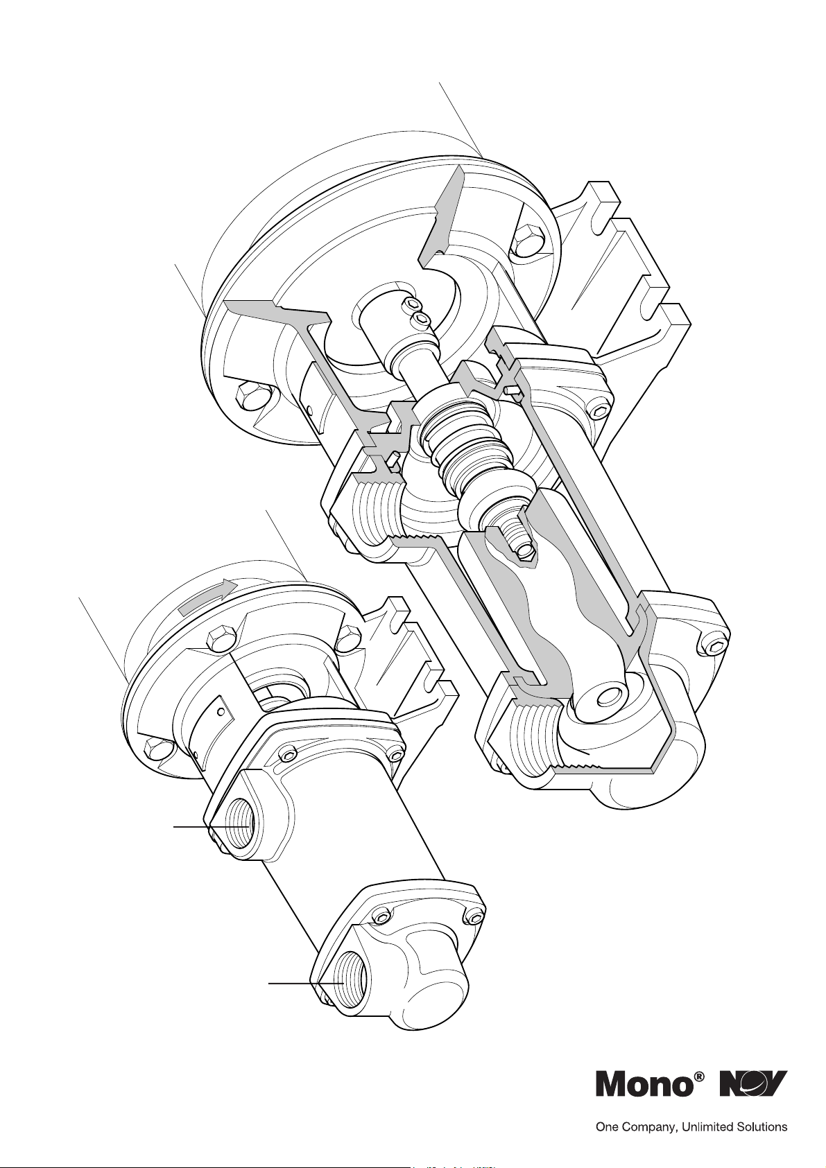
Do not fit taper thread pipe fittings to
the pump connection ports. Only use
a parallel thread pipe fitting (1" BSP)
OUTLET
MM/ML RANGE
Section 4, Page 1
Issued – November 2002
INLET
Page 17
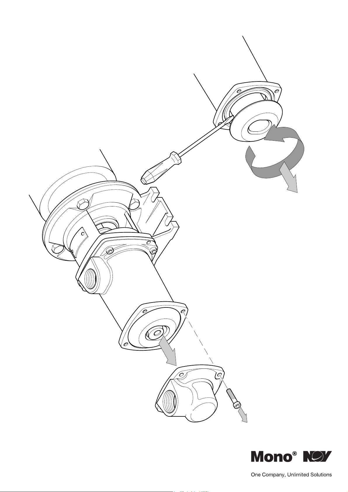
Dimantling & Assembly Diagrams
DISMANTLING
Section 4, Page 2
Issued – December 2000
1
Page 18
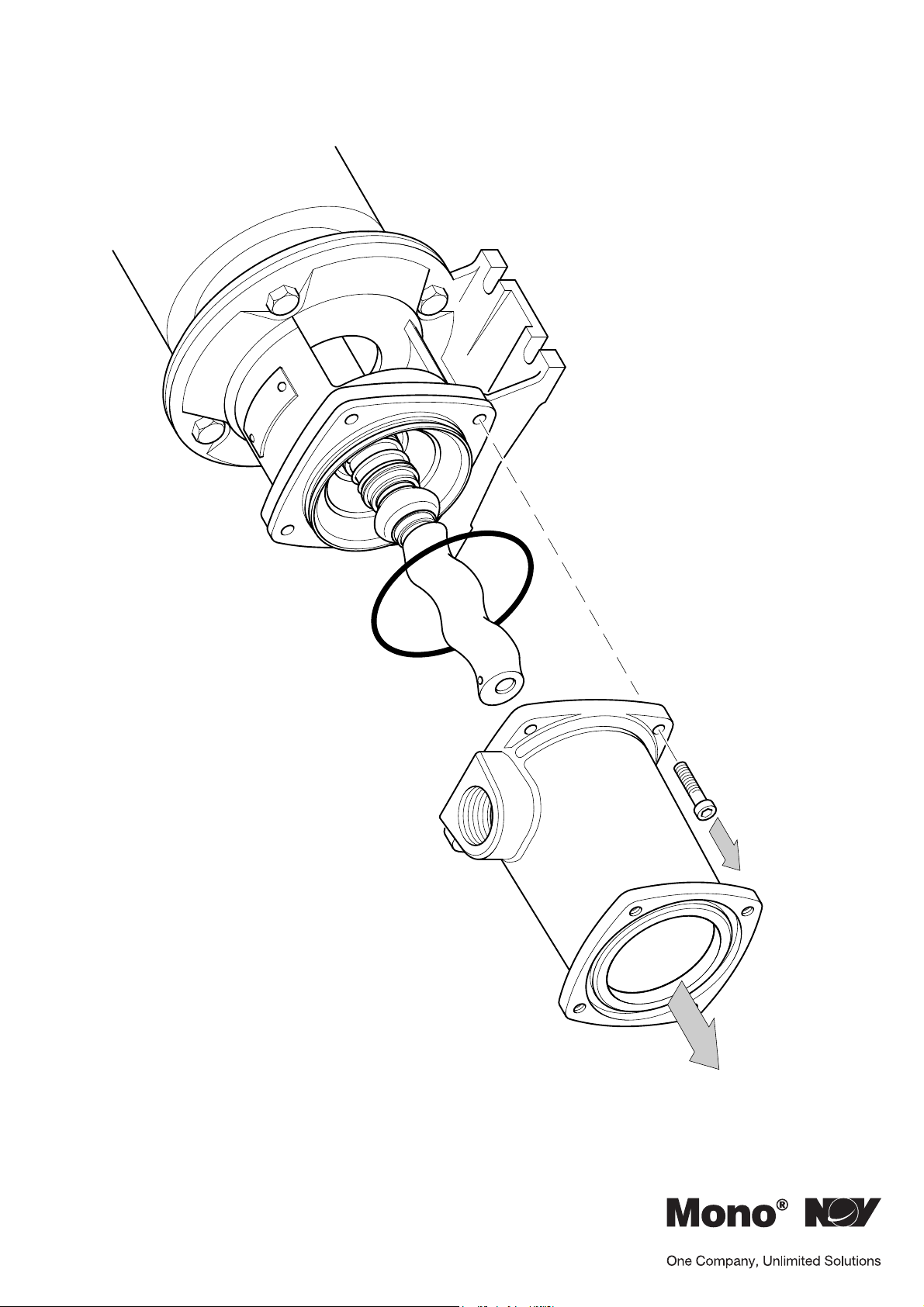
Dimantling & Assembly Diagrams
2
Section 4, Page 3
Issued – December 2000
Page 19
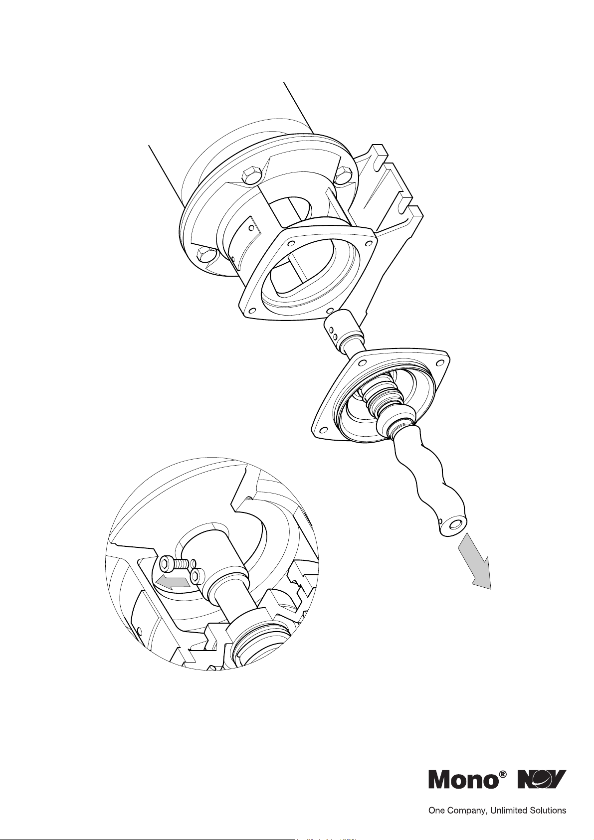
Dimantling & Assembly Diagrams
3
Section 4, Page 4
Issued – December 2000
Page 20
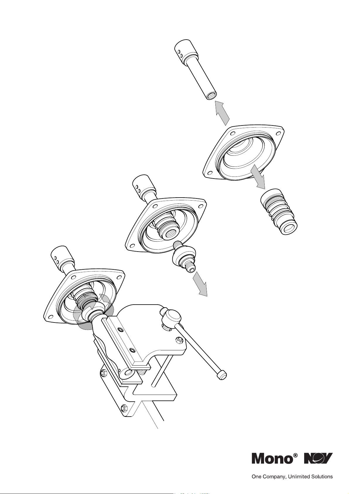
Dimantling & Assembly Diagrams
4
Section 4, Page 5
Issued – December 2000
Page 21
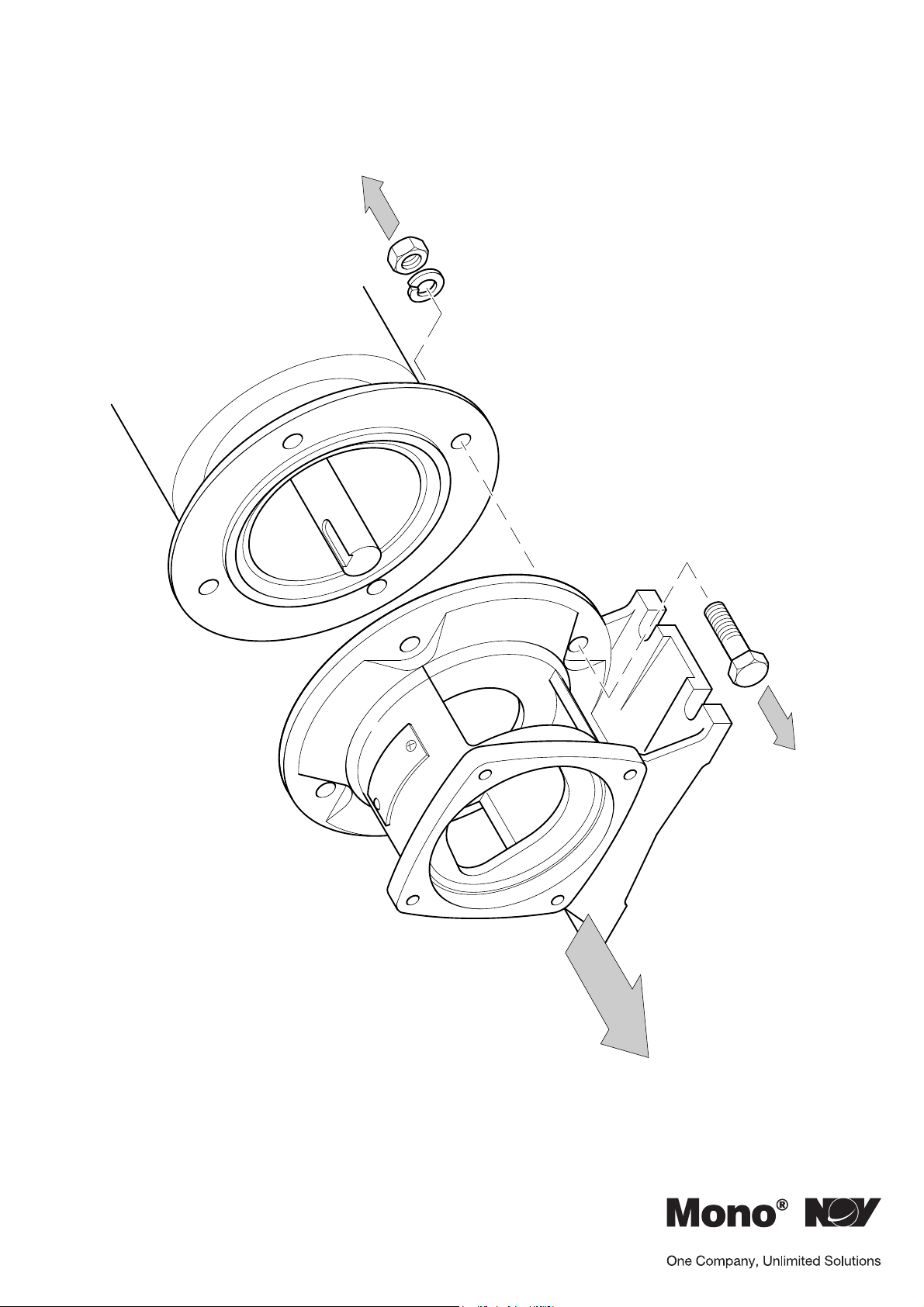
Dimantling & Assembly Diagrams
5
Section 4, Page 6
Issued – December 2000
Page 22
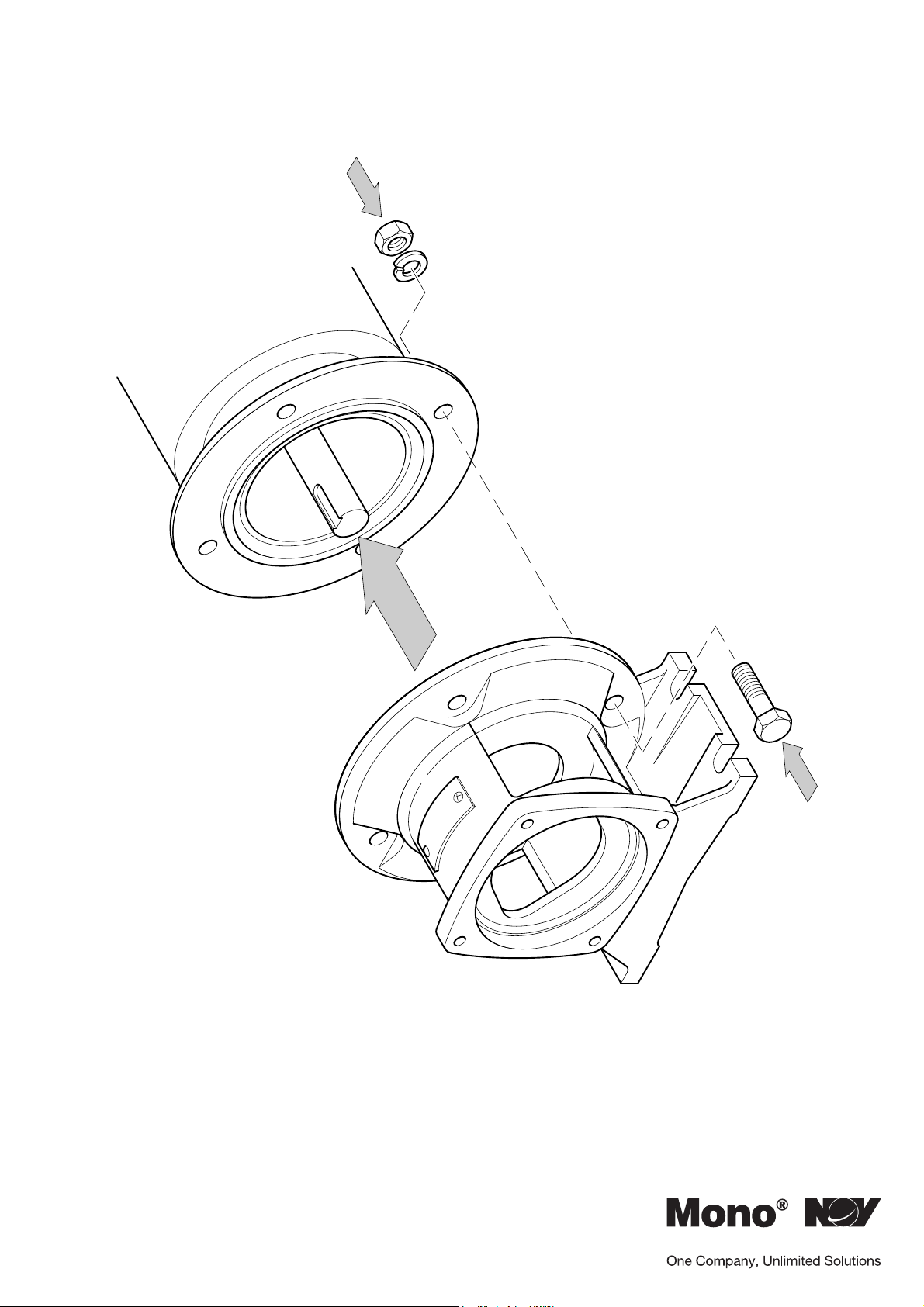
Dimantling & Assembly Diagrams
ASSEMBLY
Section 4, Page 7
Issued – December 2000
6
Page 23
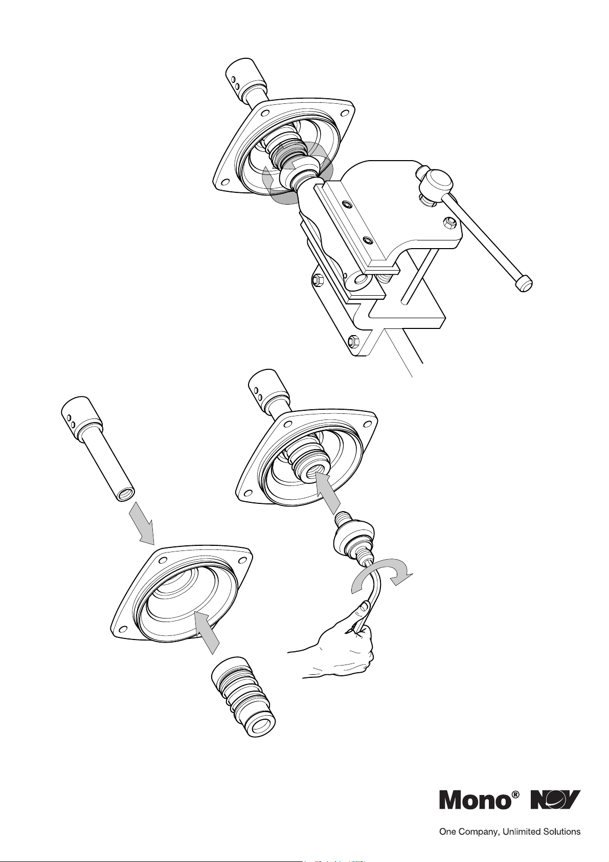
Dimantling & Assembly Diagrams
7
Section 4, Page 8
Issued – December 2000
(3Nm)
Page 24
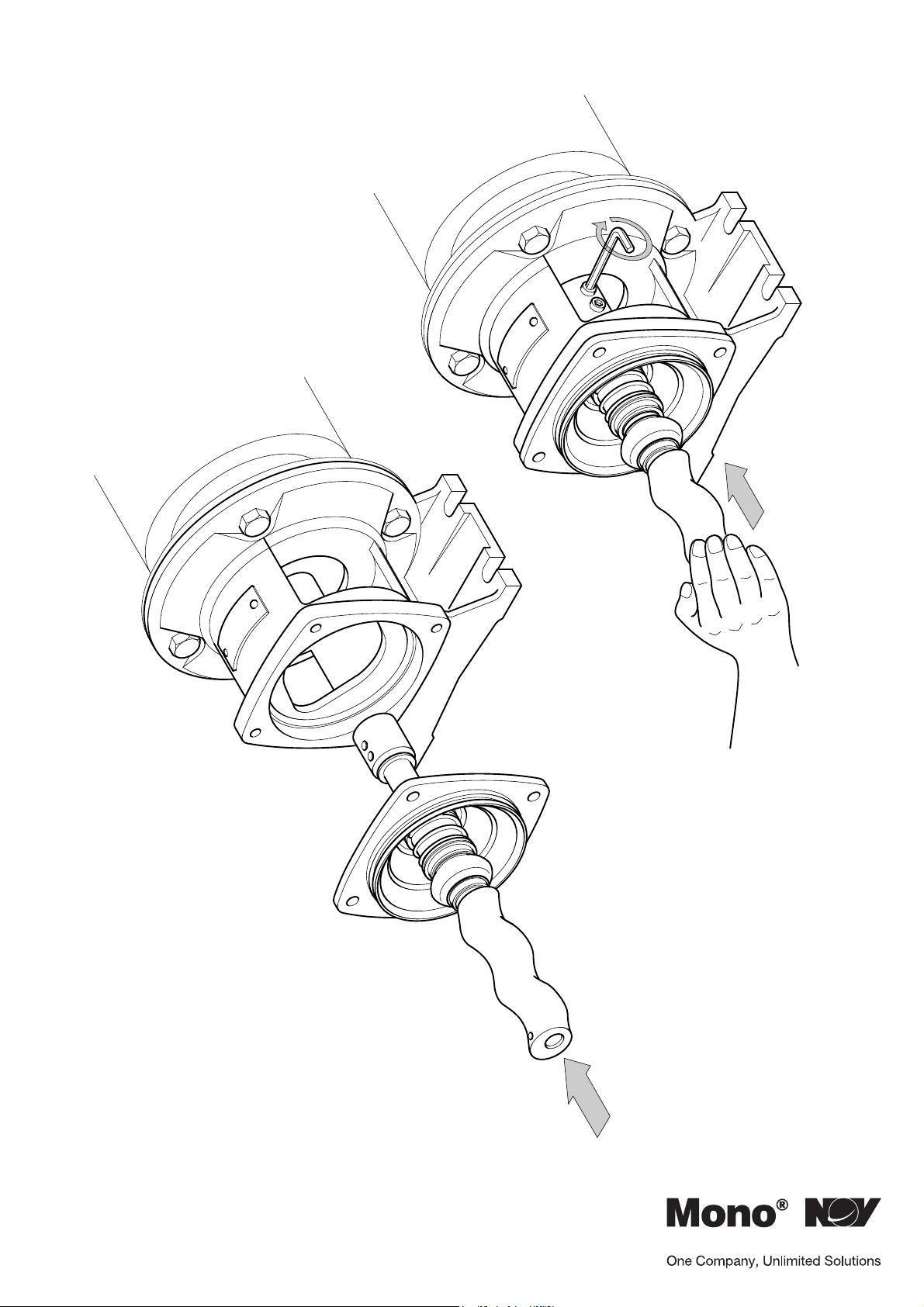
Dimantling & Assembly Diagrams
Section 4, Page 9
Issued – December 2000
8
Page 25
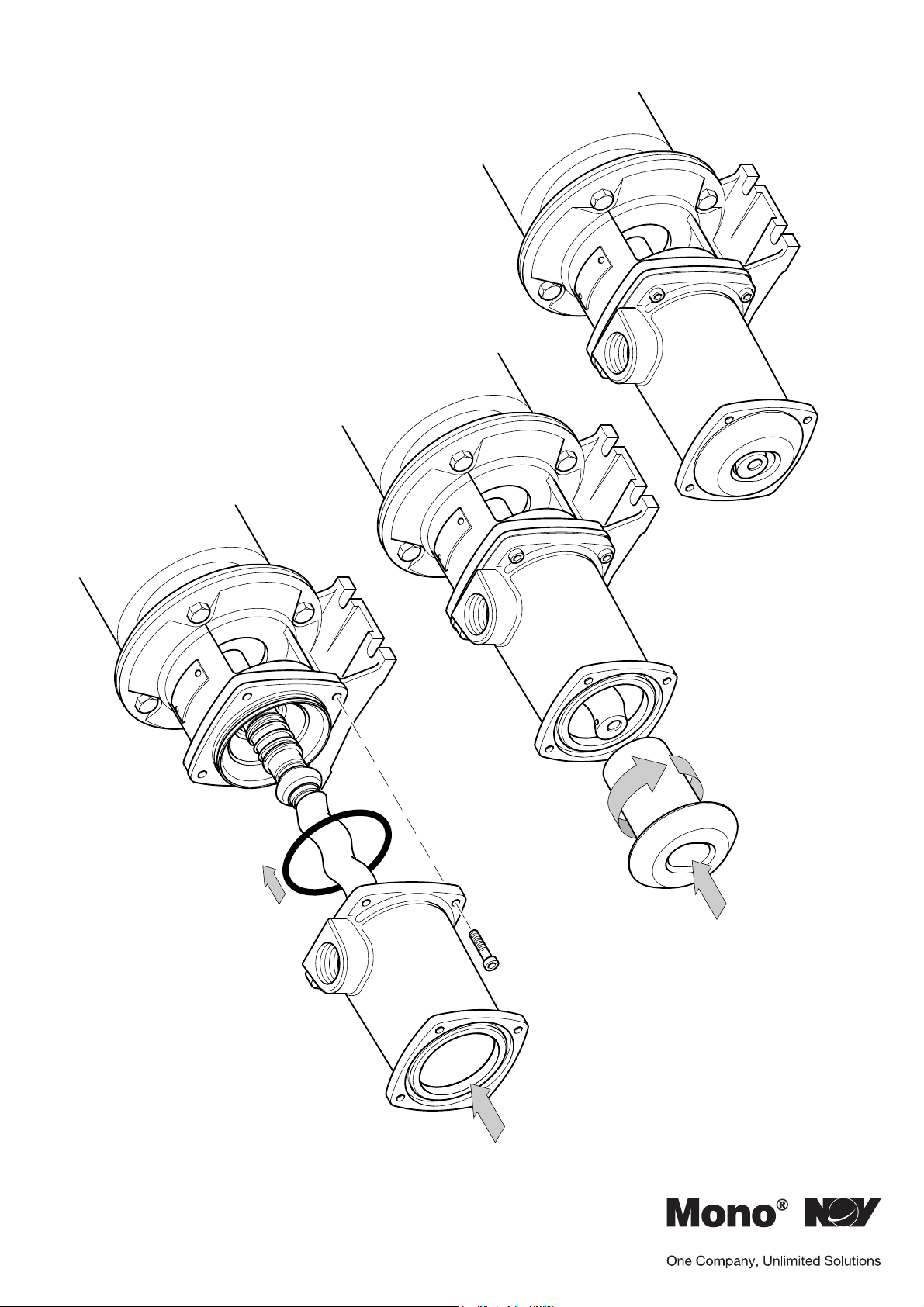
Dimantling & Assembly Diagrams
10
9
Section 4, Page 10
Issued – December 2000
Page 26
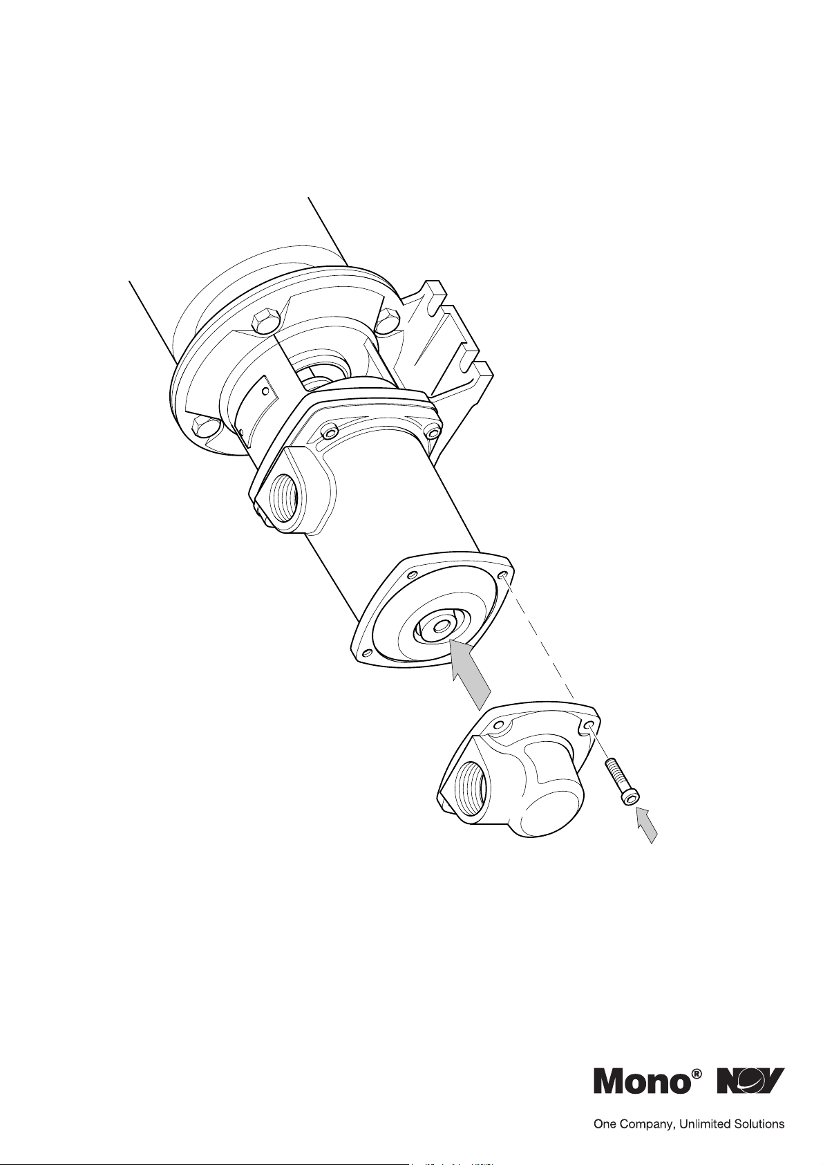
Dimantling & Assembly Diagrams
Section 4, Page 11
Issued – December 2000
11
Page 27
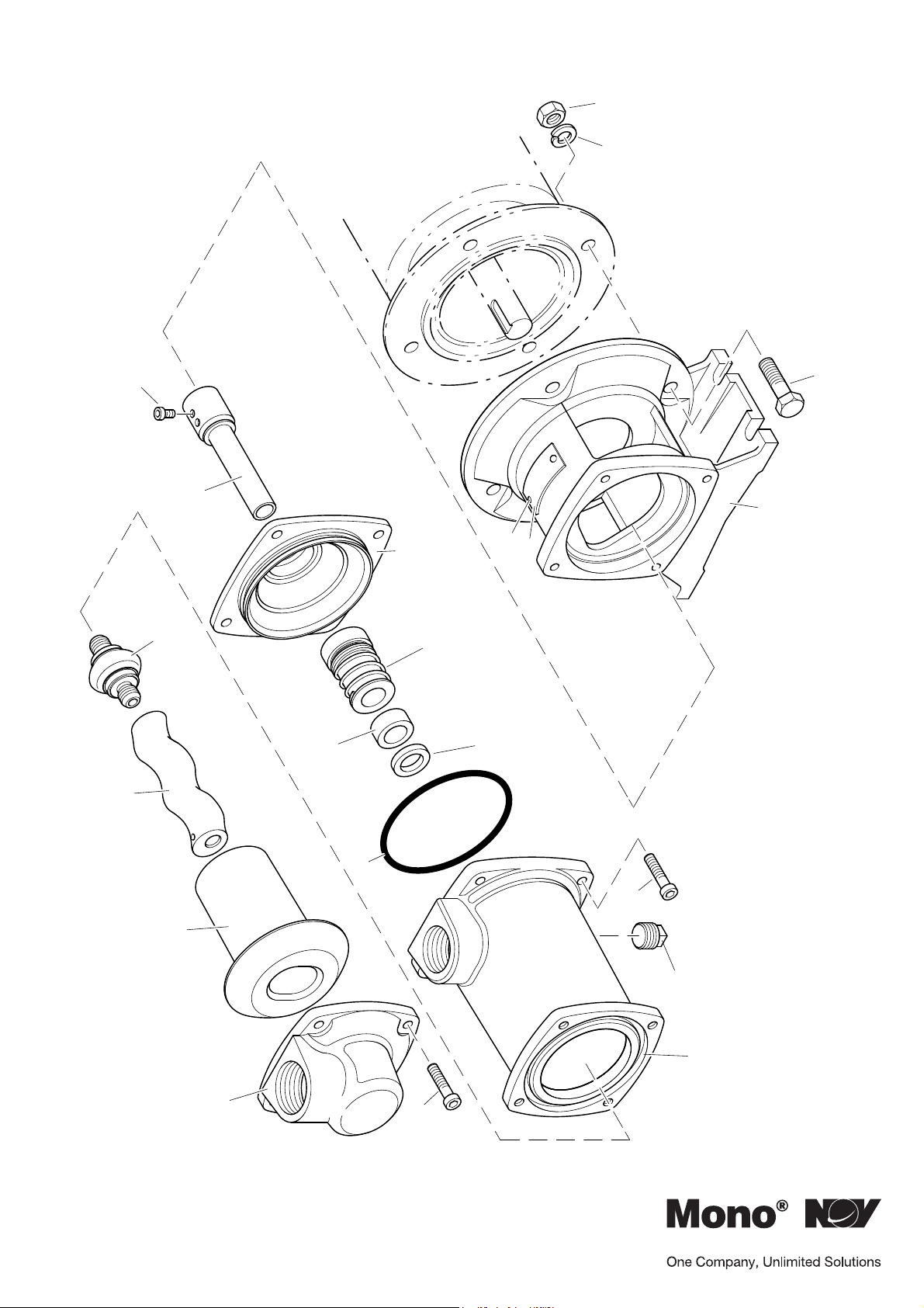
Exploded Views
N113102F
W113252F
A111101F
25A
26A
32A
6650
65A
K113242F
01A
06A
R101082F
1050
W115050F
22A
MM & ML PUMPS
24A
Section 4, Page 12
Issued – December 2000
S110870P
A112201F
P100232S
21A
A112161F
Page 28

UK and Europe
Mono Pumps Ltd, Martin Street, Audenshaw
Manchester, M34 5JA, England
T. +44 (0)161 339 9000
Americas
Monoflo SA
Ing. Huergo 2239 - B1842GGW
Monte Grande
Buenos Aires
Argentina
T. +54 4296 8997
F. +54 4284 0323
Australasia
Mono House, 338-348 Lower Dandenong Road
Mono Pumps (Australia) Pty Ltd
Mordialloc, Victoria 3195, Australia
T. +61 (0)3 9580 5211
Mono Pumps (New Zealand) Ltd
PO Box 71-021, Fremlin Place, Avondale
Auckland 7, New Zealand
T. +64 (0)9 829 0333
Asia
Mono Pumps Ltd, No. 500 YaGang Road
Lujia Village, Malu, Jiading District
Shanghai 201801, P.R. China
T. +86 (0)21 5915 7168
www.mono-pumps.com
NOV Monoflo, 9606 Kirkton
Houston, Texas 770495, USA
T. +1 281 200 1200
E. inquire@mono
o.com
 Loading...