

Page 1
MonnitLink™ Cellular Gateway
Quick Start Guide For Use With iMonnit Online Software
MonnitLink Cellular Gateway Quick Start
1. Create and setup your iMonnit™ account.
2. Connect and power on the gateway.
(International cellular gateways require additional
conguration. Please see International Cellular
Gateway quickstart guide.)
IMPORTANT!
DO NOT power up your cellular gateway until after you have created an
account on iMonnit.com and added your cellular gateway and wireless
sensors to the account. Also, when setting up your sensing network,
please make sure your sensors are at least 3-5 feet away from the gateway, and the sensors are at least 1 foot apart from each other.
Create and Setup Your iMonnit Account
• Visit http://www.imonnit.com to create an iMonnit online
sensor monitoring account.
• Follow the on-screen instructions to enter your account
and contact information.
• You will be prompted to create your rst sensor network.
Simply enter a name for your network.
• Next you will be prompted to add a wireless gateway
and wireless sensors to your network.
MonnitLink Cellular Gateway Setup
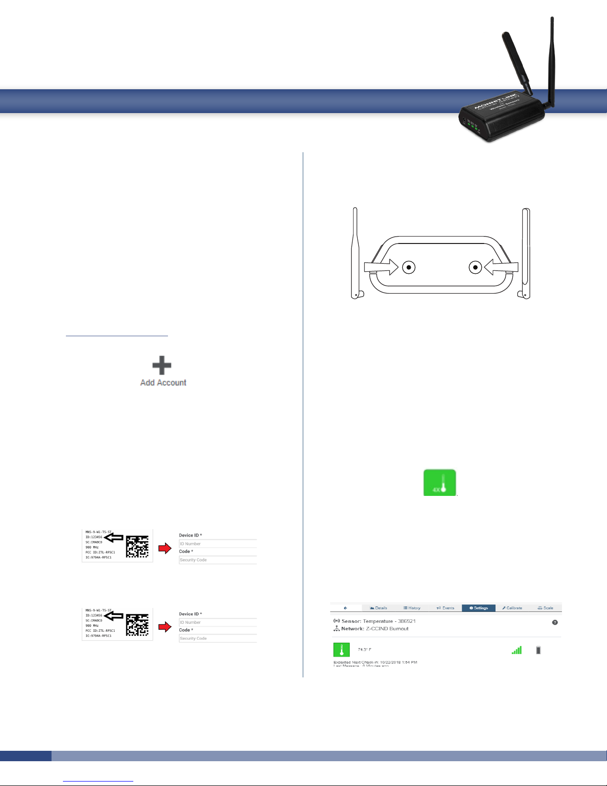
• Attach the Antenna’s to the gateway (Sensor RF
antenna on left, Cellular antenna on right).
• Plug the power supply into a power outlet then connect
to the gateway.
• Turn the power switch on (battery backup models only)
• Check that the three LED lights on the front of the gateway change to green. Once all three lights turn green,
your network is ready to use.
Using Your Wireless Sensors
• From the Overview Page of iMonnit, click “Gateways”
and check that your gateway status has changed to
active.
CellularSensor RF
• Enter the information from your MonnitLink™
gateway then click the “Assign Gateway” button.
• Enter the information from your rst wireless
sensor then click the “Assign Sensor” button.
• On the next screen, enter a name for the wireless sensor and use the drop down to tell us how you are going
to be using the wireless sensor. (This allows us to sug-
gest settings for your sensor.) When nished, click the
“Continue” button.
• Repeat these steps to add any additional wireless
sensors to your network.
• From the Overview Page of iMonnit, click “Sensors” to
return to the sensors overview page.
• Click on a sensor’s information to access detailed
information for that sensor.
• Click the “Settings” tab from a sensor’s detail view, to
change sensor settings.
• Insert batteries into the wireless sensors.
• Check that the sensors change to active as batteries
are inserted. (You may need to click the refresh button
at the top, right side of overview.)
Page 2
• The iMonnit online software is now collecting your
sensor data.
Note: Any change made to a sensor’s settings will be downloaded to
the sensor on the next sensor heartbeat (check-in). Once a change
has been made and “Saved,” you will not be able to edit that sensor’s
congurations again until the sensor has downloaded the new setting.
If you want to force a sensor to download new settings, you can power
cycle the sensor by removing the battery, waiting 30 seconds, then
reinsert the battery.
Setting Up Sensor Notications
• Notications can be created, deleted or edited for any
sensor or group of sensors by clicking on “Events” in the
main menu.
Toggle On/O Click to Open Detail View Send Test Edit Delete
• When creating a notication, you will need to select the
type of notication to create.
• Sensor Reading - Alert based on sensor reading or sensing
activity.
• Battery - Alert based on battery power remaining.
• Device Inactivity - Alert when a sensor has not checked in.
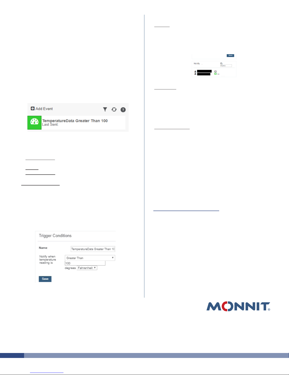
• Trigger Conditions - Set notication parameters such as
name, message and sensor conditions that will cause
the notication to be sent.
• Actions - Select the user(s) to receive the notication
and click the arrow button to add them to the recipient
list. By default, email notications are activated. Clicking
the notication delivery method icon toggles them on
and o (green is on, grey is o).
• Sent From - Assign devices (sensors and gateways) that
will cause the notication to be sent. When a notication
is sent from the system, it will automatically include the
device name and the data that caused the notication to
be sent. A single notication can be assigned to multiple
sensors or gateways.
• Devices to Notify - If you have a Monnit Control or
Notier A/V on your network, you will see a “Devices to
Notify” tab. This allows the notication to interact with
these devices. Add a device and click the control icons
to toggle their settings.
Note: Control devices have two relays per device that are controlled
separately. You can turn a relay on, o or toggle the state. You can
also set a duration by clicking on the timer icon. This will perform the
selected toggle (on/o/toggle) for a set duration, then change back.
For more detailed instructions, documentation,
“how-to” guides and video demonstrations on using
Monnit wireless sensors, wireless gateways and
iMonnit software, visit our support page at
http://www.monnit.com/support/.
Monnit, Monnit Logo, MonnitLink and iMonnit are trademarks of Monnit, Corp.
© 2009-2015 Monnit Corp. All Rights Reserved.
Monnit Corporation
4403 South 500 West
Murray, UT 84123
801-561-5555
www.monnit.com
MQS-023-2D (09/15)
 Loading...