

Page 1

Monnit Corporation | www.monnit.com | (801) 561-5555
3400 South West Temple, Salt Lake City, Utah, 84115
1
Monnit
G2XL-Generation 2 eXreame Long Range Wireless Module
Product Manual
Technical Overview
General Description
Monnit G2XL delivers transformative RF performance
in a compact, nano-power module capable of
delivering a 50+ mile range (LOS) performance while
consuming 1.0uA between transmissions. Monnit has
integrated this module with various sensor types to
provide a long range wireless sensing solution.
Additionally, the module supports flexible transmit
power options, data rate manipulation, over-the-air
upgradeability, data logging, robust link-level security
encryption, and over 20 embedded digital and analog
peripherals for end-application utilization.
Monnit integrates these modules into gateway and
sensor products for both OEM and direct customers.
Monnit’s solutions target enterprise customers,
enabling them to obtain the benefits of the IOT
revolution and reach all corners of the globe.
Principle of Operation
The module contains three different operation profiles
to facilitate data links: PEER, BSN, and EDN.
Additionally, the module can be loaded with standard
application firmware with a UART AT interface or a
more sophisticated API mode.
PEER devices are used to facilitate point to point
streaming of information from one device to another.
BSN or EDN modes create point to multi-point ultralow power networking topology for sensors and
gateways.
Module Specifications
• • Communication: RF 900 MHz FHSS
• Dimensions: 1.6” x 0.9” x 0.185”
• Antenna Ports: 2x U.FL orAPEX
• Operating Temperature: -40° to 85°C (-40° to 185°F) The Leader in Low Cost Wireless Sensors
Page 2
Monnit Corporation | www.monnit.com | (801) 561-5555
3400 South West Temple, Salt Lake City, Utah, 84115
2
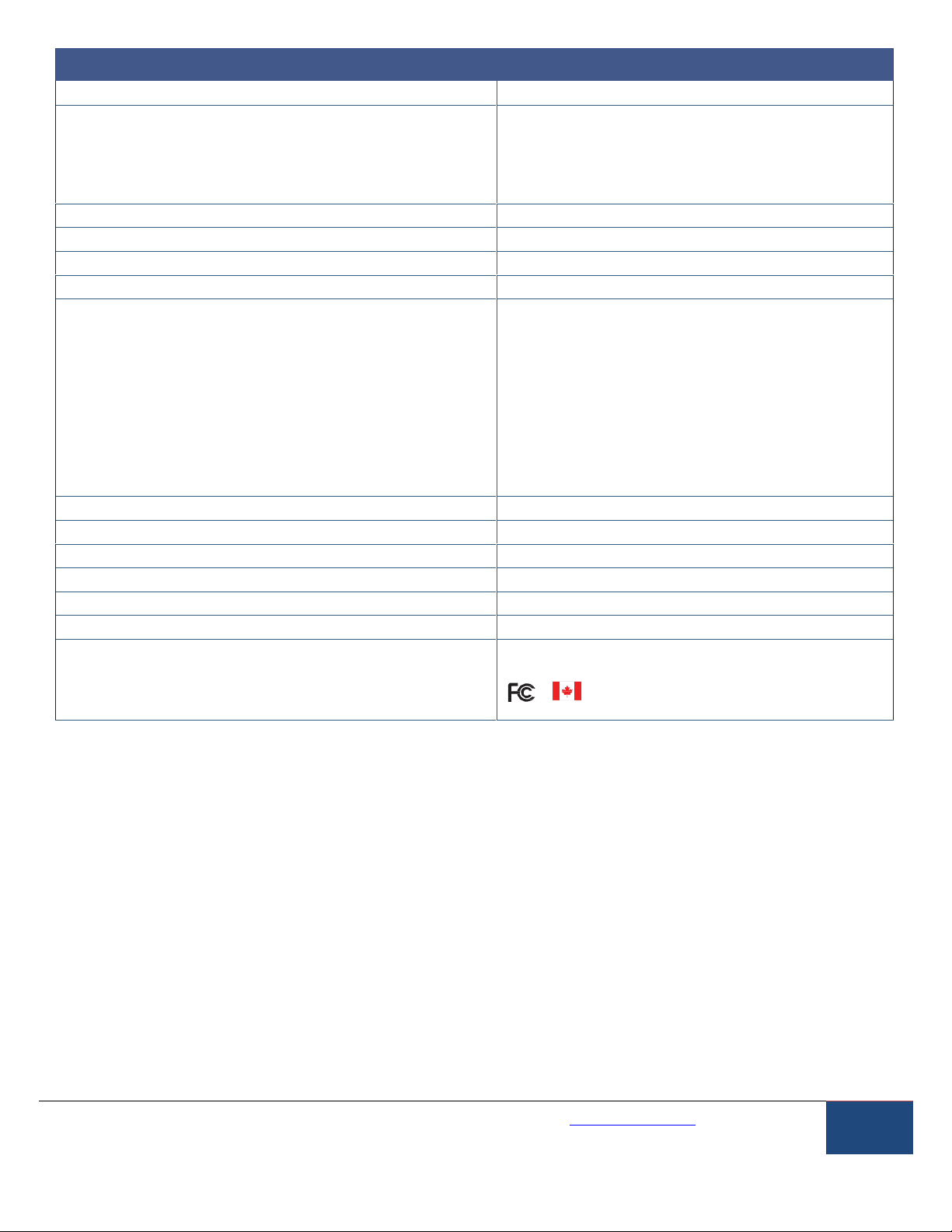
Technical Specifications
Supply Voltage
2.4 - 3.8 VDC
Current Consumption
0.7 µA (sleep mode)
1 mA (radio idle/off mode)
4 mA (measurement mode)
5 mA (radio RX mode)
650 mA @3.6V(radio TX mode max)
Operating Temperature Range (Board Circuitry and Coin Cell)
-40°C to +85°C ( -40°F to +185°F )
Optimal Battery Temperature Range (AA)
+10°C to +50°C ( +50°F to +122°F )
Antenna Ports
2x U.FL orAPEX
Wireless Range
Up to 50 miles line-of-sight
RF Symbol Rates, Sub-modulation, and Data Rates
400 KSPS GFSK 400 Kbps
400 KSPS GFSK+DSSS1 200 Kbps
400 KSPS GFSK+DSSS2 100 Kbps
400 KSPS GFSK+DSSS4 50 Kbps
400 KSPS GFSK+DSSS8 25 Kbps
10 KSPS GFSK 10 Kbps
10 KSPS GFSK+DSSS1 5 Kbps
10 KSPS GFSK+DSSS2 2.5 Kbps
10 KSPS GFSK+DSSS4 1.25 Kbps
10 KSPS GFSK+DSSS8 625 bps
Channel Spacing
10 KSPS : 50KHz, 400 KSPS : 500KHz
Channel Totals
10 KSPS : 514 channels, 400 KSPS : 51 channels
RF Output Range
-13dBm to +30dBm
Receiver Sensitivity
-100 dBm (400Kbps) to -127 dBm (625 bps)
Receiver Saturation
+10dBm
Security
Diffie-Hellman Key Exchange + AES-128 CTR
Certifications
Industry
Canada
Caution/Notice:
This module is designed for use in an ordinary environment (normal room temperature, humidity and atmospheric
pressure). Do not use this sensor under the following conditions as these factors can deteriorate the product
characteristics and cause failures and burn-out.
• Corrosive gas or deoxidizing gas - chlorine gas, hydrogen sulfide gas, ammonia gas, sulfuric acid gas, nitric oxides
gas,
etc.).
• Volatile or flammable gas.
• Dusty conditions.
• Under low or high pressure.
• Wet or excessively humid locations.
• Places with salt water, oils chemical liquids or organic solvents.
• Where there are excessively strong vibrations.
• Other places where similar hazardous conditions exist.
Use this module within the specified temperature range. Higher temperature may cause deterioration of the
characteristics or the material quality of this product.
Page 3
Monnit Corporation | www.monnit.com | (801) 561-5555
3400 South West Temple, Salt Lake City, Utah, 84115
3
RF,Power,and Data Interfaces
RF Connectors
The module supports up to two U.FL/APEX connectors. The end-customer must connect an antenna to
all antenna ports used in a customer’s application. Using an antenna port without a 50 ohm termination
constitutes misuse and may cause damage to module. Special care must be taken to ensure this situation does
not occur.
Power Warning
Hardware cannot withstand negative voltage. Please take care when connecting power to module.
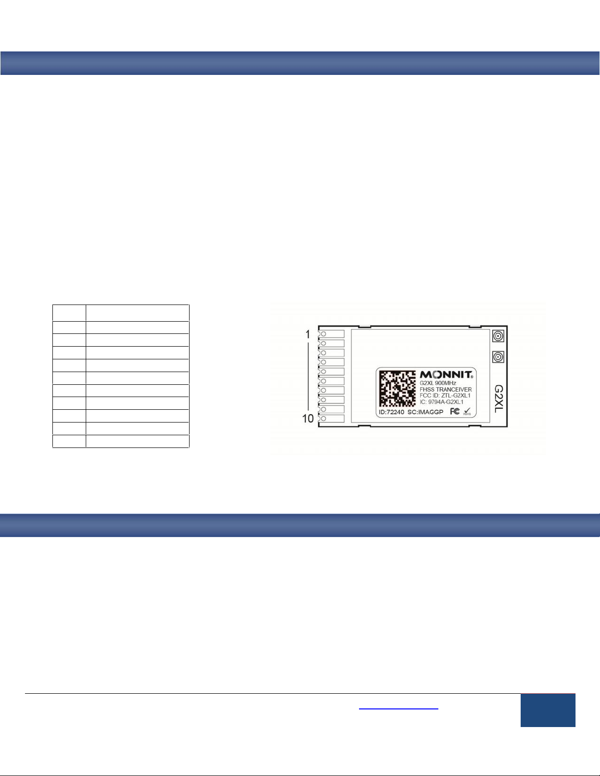
Data Connections
The following signals pins are available for connection to host hardware.
PIN
SIGNAL
1
ACT
2
nCTS
3
TX
4
GROUND
5
RX
6
nRTS
7
nRST
8
AN0
9
ACTL
10
2.4 - 3.8 VDC
Communication Protocol
Information relating to the communication protocol for this module are contained in the following documents and
can be obtained under NDA with Monnit corporation.
GWAPI V1.9
SensorAPI V1.3
Page 4

Monnit Corporation | www.monnit.com | (801) 561-5555
3400 South West Temple, Salt Lake City, Utah, 84115
4
Agency Certifications
United States FCC Module Approval
The G2XL Module complies with Part 15 of the FCC rules and regulations. These limits are designed to
provide reasonable protection against harmful interference in a residential installation. This equipment
generates, uses, and can radiate radio frequency energy and, if not installed and used in accordance with the
instruction manual, may cause harmful interference to radio communications. However, there is no guarantee
that interference will not occur in a particular installation. If this equipment does cause harmful interference to
radio or television reception, which can be determined by turning the equipment off and on, the user is
encouraged to try to correct the interference by one of more of the following measures:
• Reorient or relocate the receiving antenna
• Increase the separation between the equipment and receiver
• Connect the equipment into an outlet on a circuit different from that to which the receiver is connected.
• Consult the dealer or an experienced radio/TV technician for help.
Warning:Changes or modifications not expressly approved by Monnit could void the user’s authority to operate
the equipment.
This device complies with part 15 of the FCC Rules. Operation is subject to the following two conditions:
(1) This device may not cause harmful interference, and
(2) This device must accept any interference received, including interference that may cause undesired
operation.
Canada IC
English
Under Industry Canada regulations, this radio transmitter may only operate using an antenna of a type and maximum (or
lesser) gain approved for the transmitter by Industry Canada. To reduce potential radio interference to other users, the
antenna type and its gain should be so chosen that the equivalent isotopically radiated power (e.i.r.p.) is not more than
that necessary for successful communication.
The radio transmitter (IC: 9794A-G2XL1) has been approved by Industry Canada to operate with the antenna types listed
with the maximum permissible gain and required antenna impedance for each antenna type indicated. Antenna types not
included in this list, having a gain greater than the maximum gain indicated for that type, are strictly prohibited for use with
this device.
This device complies with Industry Canada license-exempt RSS standard(s). Operation is subject to the following two
conditions: (1) this device may not cause interference, and (2) this device must accept any interference, including
interference that may cause undesired operation of the device.
Page 5

Monnit Corporation | www.monnit.com | (801) 561-5555
3400 South West Temple, Salt Lake City, Utah, 84115
5
French
Conformément à la réglementation d’Industrie Canada, le présent émetteur radio peut fonctionner avec une antenne d’un
type et d’un gain maximal (ou inférieur) approuvé pour l’émetteur par Industrie Canada. Dans le but de réduire les risques
de brouillage radioélectrique à l’intention des autres utilisateurs, il faut choisir le type d’antenne et son gain de sorte que la
puissance isotrope rayonnée équivalente (p.i.r.e.) ne dépasse pas l’intensité nécessaire à l’établissement d’une communication satisfaisante.
Le présent émetteur radio (IC: 9794A-G2XL1) a été approuvé par Industrie Canada pour fonctionner avec les types
d’antenne énumérés et ayant un gain admissible maximal et l’impédance requise pour chaque type d’antenne. Les types
d’antenne non inclus dans cette liste, ou dont le gain est supérieur au gain maximal indiqué, sont strictement interdits
pour l’exploitation de l’émetteur.
Le présent appareil est conforme aux CNR d’Industrie Canada applicables aux appareils radio exempts de licence.
L’exploitation est autorisée aux deux conditions suivantes : (1) l’appareil ne doit pas produire de brouillage, et (2)
l’utilisateur de l’appareil doit accepter tout brouillage radioélectrique subi, méme si le brouillage est susceptible d’en compromettre le fonctionnement.
FCC/IC Approved Antennas
The G2XL Module can be installed utilizing antennas and cables constructed with standard connectors (Type-N,
SMA, TNC, and so forth.) if the installation is performed professionally and according to FCC guidelines. For
installations not performed by a professional, non-standard connectors (RPSMA, RPTNC, and so forth.) must
be used. The modules are FCC/IC approved for fixed base station and mobile applications. If the antenna is
mounted at least 21.7cm (9 in) in the USA, or 32.1cm (12.6 in) in Canada from nearby persons, the application
is considered a mobile application. Antennas not listed in the table must be tested to comply with FCC Section
15.203 (Unique Antenna Connectors) and Section 15.247 (Emissions).
G2XL modules have been tested and approved for use with all the antennas listed in the tables below. (Cable-
loss IS required when using gain antennas as shown below.)
Part Number
Manufacturer
Description
Required Cable Loss
XQZ-900E-2
Xianzi
3 dBi Dipole Omni
0 dB
HG905RD-RSP
Hyperlink
5 dBi Dipole Omni
0.44 dB
HG908U-PRO
Hyperlink
8dBi Fiberglass Omni
3.48 dB
HG8909P
Hyperlink
9dBi Flat Panel
3.54 dB
HG914YE-NF
Hyperlink
14dBi Yagi
10.74 dB
OEM Labeling Requirements
The Original Equipment Manufacturer (OEM) must ensure that FCC and IC labeling requirements are met.
This includes a clearly visible label on the outside of the final product enclosure that displays the contents
shown in the figure below.
Required FCC/IC Label for OEM products containing the RFXL Module:
Contains FCC ID: ZTL-G2XL1
Contains Wireless Module IC: 9794A-G2XL1
The enclosed device complies with Part 15 of the FCC Rules. Operation is subject to the following two conditions: (i.)
this device may not cause harmful interference and (ii.) this device must accept any interference received, including
interference that may cause undesired operation.
Page 6

Monnit Corporation | www.monnit.com | (801) 561-5555
3400 South West Temple, Salt Lake City, Utah, 84115
6
OEM Documentation Requirements
RF Exposure for FCC
WARNING: To satisfy FCC RF exposure requirements for mobile transmitting devices, a separation distance
of 21.7 cm or more should be maintained between the antenna of this device and persons during device
operation. To ensure compliance, operations at closer than this distance is not recommended. The antenna
used for this transmitter must not be co-located in conjunction with any other antenna or transmitter.
The preceding statement must be included as a CAUTION statement in OEM product manuals in order to alert users of FCC
RF Exposure compliance.
RF Exposure for IC
WARNING: To satisfy IC RF exposure requirements for mobile transmitting devices, a separation distance
of 32.1 cm or more should be maintained between the antenna of this device and persons during device
operation. To ensure compliance, operations at closer than this distance is not recommended. The antenna
used for this transmitter must not be co-located in conjunction with any other antenna or transmitter.
AVERTISSEMENT: Pour satisfaire IC RF exigences d’exposition pour les appareils mobiles de transmis-
sion, une distance de séparation de 32,1 cm ou plus doit être maintenue entre l’antenne de cet appareil et
des personnes pendant le fonctionnement de l’appareil. Pour assurer la conformité, les opérations au plus
près que cette distance ne sont pas recommandés. L’antenne utilisée pour cet émetteur ne doit pas être
situé en conjonction avec une autre antenne ou émetteur.
.
The preceding statement must be included as a CAUTION statement in OEM product manuals in order to alert users of IC
RF Exposure compliance.
OEM Notices
IMPORTANT: The G2XL Module has been certified by the FCC for use with other products without any
further certification (as per FCC section 2.1091). Modifications not expressly approved by Monnit
Corporation could void the user's authority to operate the equipment.
IMPORTANT: OEM Integrators must test final product to comply with unintentional radiators (FCC section
15.107 & 15.109) before declaring compliance of their final product to Part 15 of the FCC Rules. Other
compliance testing may also apply (for example, PC peripheral requirements, etc.).
IMPORTANT: The G2XL module has been certified for remote and base radio applications. If the module will
be used for portable applications, the device must undergo SAR testing.
IMPORTANT: In the event that the minimum distance requirement or if the module is co-located with other
transmitters, then current FCC and IC authorization is no longer valid and the FCC ID or IC number cannot
be used on the final product. In these circumstances, the OEM integrator will be responsible for reevaluating the end product (including the transmitter) and obtaining a separate FCC and IC authorization.
Page 7

Monnit Corporation | www.monnit.com | (801) 561-5555
3400 South West Temple, Salt Lake City, Utah, 84115
7
Warranty and Support
Warranty Information
(a) Monnit warrants that Monnit-branded products will be free from defects in materials and workmanship for a period of
one (1) year from the date of delivery with respect to hardware and will materially conform to their published specifications
for a period of one (1) year with respect to software. Monnit may resell sensors manufactured by other entities and are
subject to their individual warranties; Monnit will not enhance or extend those warranties. Monnit does not warrant that
the software or any portion thereof is error free. Monnit will have no warranty obligation with respect to Products subjected
to abuse, misuse, negligence or accident. If any software or firmware incorporated in any Product fails to conform to the
warranty set forth in this Section, Monnit shall provide a bug fix or software patch correcting such non-conformance within
a reasonable period after Monnit receives from Customer (i) notice of such non-conformance, and (ii) sufficient information regarding such non-conformance so as to permit Monnit to create such bug fix or software patch. If any hardware
component of any Product fails to conform to the warranty in this Section, Monnit shall, at its option, refund the purchase
price less any discounts, or repair or replace non-conforming Products with conforming Products or Products having substantially identical form, fit, and function and deliver the repaired or replacement Product to a carrier for land shipment to
customer within a reasonable period after Monnit receives from Customer (i) notice of such non-conformance, and (ii) the
non-conforming Product provided; however, if, in its opinion, Monnit cannot repair or replace on commercially reasonable
terms it may choose to refund the purchase price. Repair parts and replacement products may be reconditioned or new.
All replacement products and parts become the property of Monnit. Repaired or replacement products shall be subject to
the warranty, if any remains, originally applicable to the product repaired or replaced. Customer must obtain from Monnit a
Return Material Authorization Number (RMA) prior to returning any Products to Monnit. Products returned under this Warranty must be unmodified.
Customer may return all Products for repair or replacement due to defects in original materials and workmanship if Mon- nit
is notified within ninety (90) days of customer’s receipt of the product. Monnit reserves the right to repair or replace
products at its own and complete discretion. Customer must obtain from Monnit a Return Material Authorization Number
(RMA) prior to returning any products to Monnit. Products returned under this Warranty must be unmodified and in original
packaging. Monnit reserves the right to refuse warranty repairs or replacements for any products that are damaged or not
in original form. For products outside the ninety-day warranty period repair services are available at Monnit at standard
labor rates for a period of one year from the Customer’s original date of receipt.
(b) As a condition to Monnit’s obligations under the immediately preceding paragraphs, Customer shall return Products to
be examined and replaced to Monnit’s facilities, in shipping cartons which clearly display a valid RMA number provided
by Monnit. Customer acknowledges that replacement products may be repaired, refurbished or tested and found to be
complying. Customer shall bear the risk of loss for such return shipment and shall bear all shipping costs. Monnit shall
deliver replacements for Products determined by Monnit to be properly returned, shall bear the risk of loss and such costs
of shipment of repaired products or replacements, and shall credit Customer’s reasonable costs of shipping such returned
Products against future purchases.
(c) Monnit’s sole obligation under the warranty described or set forth here shall be to repair or replace non-conforming
products as set forth in the immediately preceding paragraph, or to refund the documented purchase price for nonconforming Products to Customer. Monnit’s warranty obligations shall run solely to Customer, and Monnit shall have no
obligation to customers of Customer or other users of the Products.
Page 8

Monnit Corporation | www.monnit.com | (801) 561-5555
3400 South West Temple, Salt Lake City, Utah, 84115
8
Limitation of Warranty and Remedies.
THE WARRANTY SETFORTH HEREIN IS THE ONLY WARRANTY APPLICABLE TO PRODUCTS PURCHASED BY
CUSTOMER. ALLOTHER WARRANTIES, EXPRESS OR IMPLIED, INCLUDING BUT NOT LIMITED TO THE IMPLIED
WARRANTIES OF
MERCHANTABILITY
AND FITNESS FOR A PARTICULAR PURPOSE ARE EXPRESSLY DISCLAIMED. MONNIT’S LIABIITY WHETHER IN CONTRACT, IN TORT, UNDER ANYWARRANTY, IN NEGLIGENCE OR
OTHERWISE SHALL NOT EXCEED THE PURCHASE PRICE PAID BY CUSTOMER FOR THE PRODUCT. UNDER NO
CIRCUMSTANCES SHALL MONNIT BE LIABLE FOR SPECIAL, INDIRECT OR CONSEQUENTIAL DAMAGES. THE
PRICE STATED FOR THE PRODUCTS IS ACONSIDERATION IN LIMITING MONNIT’S LIABILITY. NO ACTION, REGARDLESS OF FORM, ARISING OUT OF THIS AGREEMENT MAYBE BROUGHT BY CUSTOMER MORE THAN ONE
YEAR AFTER THE CAUSE OF ACTION HAS ACCRUED.
IN ADDITION TO THE WARRANTIES DISCLAIMED ABOVE, MONNIT SPECIFICALLYDISCLAIMS ANYAND ALL LIABILITY AND WARRANTIES, IMPLIED OR EXPRESSED, FOR USES REQUIRING FAIL-SAFE PERFORMANCE IN
WHICH FAILURE OF A PRODUCT COULD LEAD TO DEATH, SERIOUS PERSONAL INJURY, OR SEVERE PHYSI- CAL
OR ENVIRONMENTAL DAMAGE SUCH AS, BUT NOT LIMITED TO, LIFE SUPPORT OR MEDICAL DEVICES OR
NUCLEAR APPLICATIONS. PRODUCTS ARE NOT DESIGNED FOR AND SHOULD NOT BE USED IN ANY OF THESE
APPLICATIONS.
Error Reporting, Troubleshooting and Support
For technical support and troubleshooting tips please visit our support library online at http://www.monnit.com/support/. If
you are unable to solve your issue using our online support, email Monnit support at support@monnit.com with your contact information and a description of the problem, and a support representative will call you within one business day.
For error reporting, please email a full description of the error to support@monnit.com.
For more information about our products or to place an order, please contact our sales department at 801-561-5555.
Visit us on the web at www.monnit.com.
Monnit, iMonnit and all other trademarks are property of Monnit, Corp.
© 2009-2016 Monnit Corp. All Rights Reserved.
 Loading...