

Monitor Products, Inc M2400, M2200 Service Manual
MONITOR HEATING SYSTEMS
Table
of
Contents
Section
1:
Description
1-1
Specifications
(M-2400)
1-2
Special Features (M-2400)
1
-3
Safety Features (M-2400)
1-4
Specifications (M-2200)
1-5
Special
Features (M-2200)
1-6
Safety Features (M-2200)
1-7
Description
1-8
Spill
Tray
1-9
Heater Cabinet
1-10 Combustion System
1-11
Combustion Chamber
1-12 Burner
Pot
1-13
Combustion
Ring Assembly
1-14 Flame Sensor
1-15
Igniter
1-16 Combustion
Air
System
1-17
Flue
Pipe
1-18
Combustion
Blower
Motor (M-2400)
1-19 Heat Exchanger
1-20
Air
Circulation
Fan
Page
1~10
1-21
Air
Pressure Switch
1-22 Fuel Delivery System
1-23 External Fuel Tank
1-24
Fusible Link Valve
1-25 Fuel Constant Level Valve
1-26
Solenoid Pump
1-27
Electrical System
1-28
Microprocessor
1-29 Temperature Sensor
1-30 Safety Mechanism
1-31 Cloth Covered Exhaust Pipe
1-32
Air
Circulation
Fan
Guard
1-33 Fuse
1-34
Overheat Protector Switches (M-2400)
1-35
Revolution control
of
combustion blower motor
1-36
Combustion Blower Motor (M-2200)
1-37
Overheat Protector Switches (M-2200)
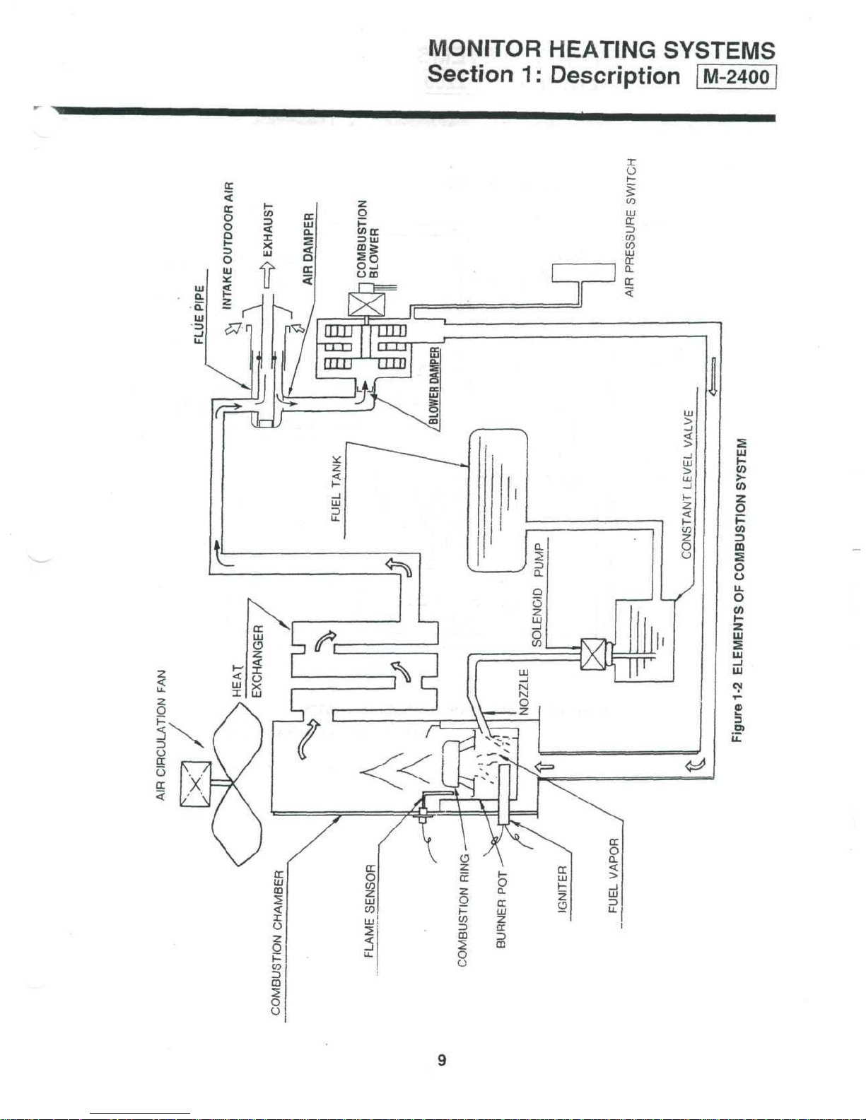
Elements
of
combustion system (M-2400)
Elements
of
combustion system (M-2200)
Section
2:
Installation
2-1
Introduction
2-2
Physical Placement
of
Heater
2-3
Drilling Requirements
2-4
Power Requirements
2-5
Fuel Tank Requirements
2-6
Temperature Sensor Wiring
Requirements
2-7
Building Codes
2-8
Un-packing
2-9
Heater Installation
Installation
Classification (M-2400)
Page
11~27
Installation Classification (M-2200)
Applicable Wall Thickness
of
Flue Pipe
Flue Pipe Clearances
2-10
Installing
an
Extension
Kit
2-11
Typical Monitor Lifter Pump Installations
2-12
Uses
for the
Elbow Adapter
Kit
2-13 Fuel Tank
Installation
2-14 Heater
Installation
Typical fuel line connections
Back
guard (M-2400)
Back guard (M-2200)
Section
3:
Operation
•
3-1
Introduction
(M-2400)
3-2
Operating Specifications (M-2400)
3-3
Introduction (M-2200)
3-4
Operating Specifications (M-2200)
3-5
Operating
Controls
and
Indicators
3-6
Pre-operation
Check List
3-7
Operation
3-8
Manual Heater Operation
3-9
Automatic
Heater
Operation
Page
28~38
3-10
Programming
the
weekly timer
for
automatic heater operation
3-11
Heat Sensor
3-12
Monitor Shutdown
3-13
Out
of
Fuel
3-14
Recovery from a Power
Failure
3-15
Recovery from Overheat Condition
3-16
Recovery from Blown Fuse
3-17 Operation
Control
system
M-2400/2200
Operation timing chart
MONITOR HEATING SYSTEMS
Table
of
Contents
Section
4:
Maintenance
Page
39—42
4-1
Introduction
4-6
Cleaning Fusible Link
Valve
Intake
4-2
Periodic Maintenance
4-7
Corrective Maintenance
4-3
Inspect Exhaust
/Air
Piping
4-8
Replacement
of
Fuses
4-4
Verify
Igniter
Operation
4-9
Fuel Contamination
4-5
Clean Fuel Constant Level
Valve
Filter
Section
5:
Servicing
Page
43—47
5-1
Introduction
5-2
Measurement
of
Fuel Flow rate
5-3
Removal
of
Water Deposits
and
Contaminants
from
Fuel Constant Level Valve
and
Fuel Lines
5-4
Cleaning
the
Burn Chamber & Burner
Pot
(M-2400)
5-5
Cleaning
the
Fuel Inlet (M-2400)
5-6
Cleaning
the
Burn Chamber & Burner
Pot
(M-2200)
5-7
Cleaning
the
Fuel Inlet (M-2200)
Section
6 :
Troubleshooting
Page
49~62
Resistance Values (M-2400)
Component Voltage Readings (M-2400)
Resistance
Values (M-2200)
Component Voltage Readings (M-2200)
Test
Point Voltage
Troubleshooting Diagrams (Mechanical)
Troubleshooting Diagrams (Electrical)
Indication
of
Failure
mode
Section
7 :
Electrical
System
Page
63—66
Schematics
Schematics (since February 2004)
Monitor 2400 Printed Circuit Board Wiring Diagram
Monitor 2200 Printed Circuit Board Wiring Diagram
SERVICE
PARTS
LIST
•
Page
67-70
Monitor 2400 Service parts list
Exploded views (M-2400)
Monitor 2200 Service parts
list
Exploded
views
(M-2200)
MONITOR
HEATING
SYSTEMS
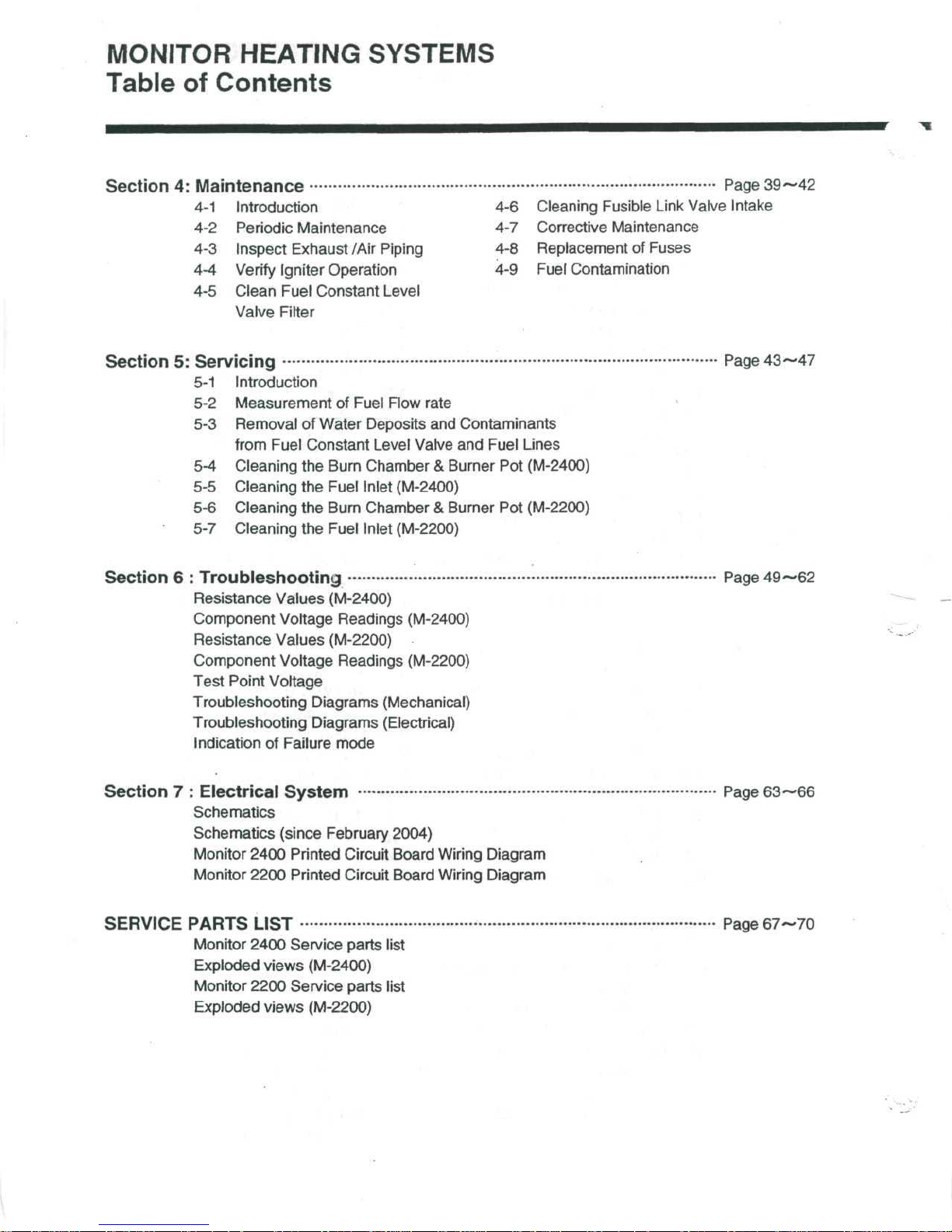
1-1
SPECIFICATIONS
Model
Fuel Type
Heater
Efficiency
Heat
Rating
Heater
Output
Fuel Tank
Fuel
Consumption
Power
Source
Power
Consumption
Heated
Vent
Dimensions
Weight
* Net
Air
Delivery
Pipe Hole
Efficiency
is
88%, A.F.U.E.
is 84%
Section
Monitor
Crystal
93%*
High : 43,000 BTU/hour
H.Medium : 32,000
L.Medium : 24,600 BTU/hour
Low:
High : 37,200 BTU/hour
H.Medium:
L.Medium:
Low:
Separate
High : 0.319
H.Medium:
L.Medium:
Low:
120
Volts
Ignition
High combustion Operation
High
to Low 4
Operations
High
: 388
H.Medium
L.Medium
Low
: 300
-inches Diameter
Height:
Width:
Depth : 14.0
82
Pounds, empty
1:
Description
2400
Clear
Kerosene
BTU/hour
16,200
13,600
0.12 Gallon/hour
BTU/hour
26,900 BTU/hour
20,700 BTU/hour
BTU/hour
(Not supplied with heater)
Gallon/hour
0.24 Gallon/hour
0.18
Gallon/hour
AC
;60Hz
: 310
Watts
steps
combustion : 56.5
Cubic feet/minute
: 388
Cubic feet/minute
: 330
Cubic feet/minute
Cubic feet/minute
26.6 inches
28.7 inches
inches
: 68
Watts(Average)
Watts(Average)
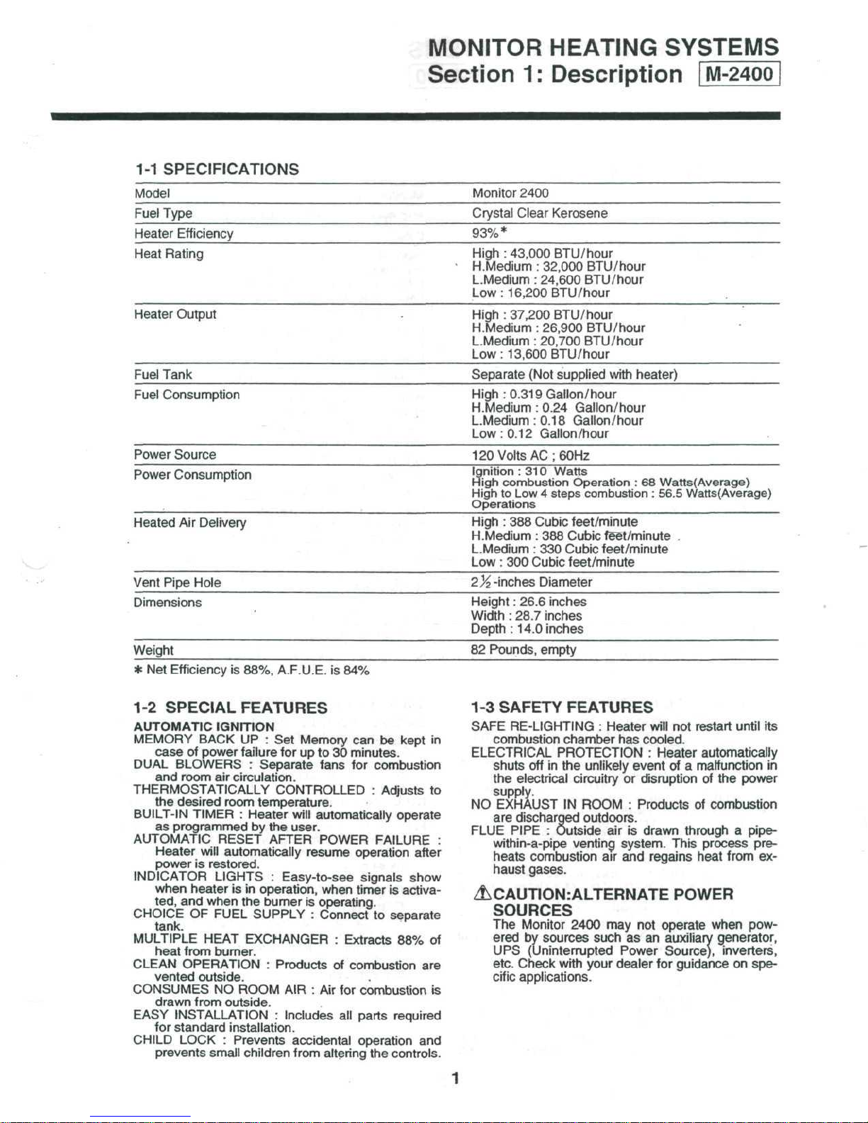
1-2
SPECIAL FEATURES
AUTOMATIC
MEMORY
case
DUAL
BLOWERS : Separate fans
and
THERMOSTATICALLY
the
BUILT-IN TIMER : Heater
as
programmed
AUTOMATIC
Heater
power
INDICATOR
when heater
ted,
CHOICE
tank.
MULTIPLE HEAT EXCHANGER : Extracts
heat
CLEAN
vented outside.
CONSUMES
drawn
EASY
INSTALLATION : Includes
for
standard
CHILD
prevents
IGNITION
BACK
of
room
desired room temperature.
is
and
OF
from burner.
OPERATION : Products
from
LOCK : Prevents accidental operation
UP : Set
power
failure
for up to 30
air
circulation.
CONTROLLED : Adjusts
will
by the
RESET AFTER POWER FAILURE
will
automatically resume operation after
restored.
LIGHTS : Easy-to-see
is in
when
the
FUEL SUPPLY : Connect
NO
RpOM
outside.
installation.
small
children
user.
operation, when timer
burner
AIR : Air for
from
Memory
is
can be
minutes.
for
automatically operate
operating.
of
combustion
all
altering
kept
combustion
signals show
is
to
separate
88% of
combustion
parts required
the
controls.
in
to
activa-
are
is
and
1-3
SAFETY FEATURES
SAFE
RE-LIGHTING : Heater
combustion chamber
ELECTRICAL
shuts
the
supply.
NO
EXHAUST
are
FLUE PIPE : Outside
:
within-a-pipe
heats
haust gases.
PROTECTION : Heater automatically
off in the
electrical
discharged outdoors.
combustion
circuitry
IN
venting system. This process
ZLCAUTIONiALTERNATE
SOURCES
The
Monitor 2400
ered
by
UPS
etc. Check with your dealer
cific
sources such
(Uninterrupted Power Source), inverters,
applications.
will
has
unlikely
or
ROOM : Products
air is
air
and
not
cooled.
event
of a
disruption
drawn through a pipe-
regains heat from
POWER
may not
operate when pow-
as an
auxiliary generator,
for
guidance
restart
until
malfunction
of the
power
of
combustion
on
its
in
pre-
ex-
spe-
MONITOR
HEATING
SYSTEMS
Section
1-4
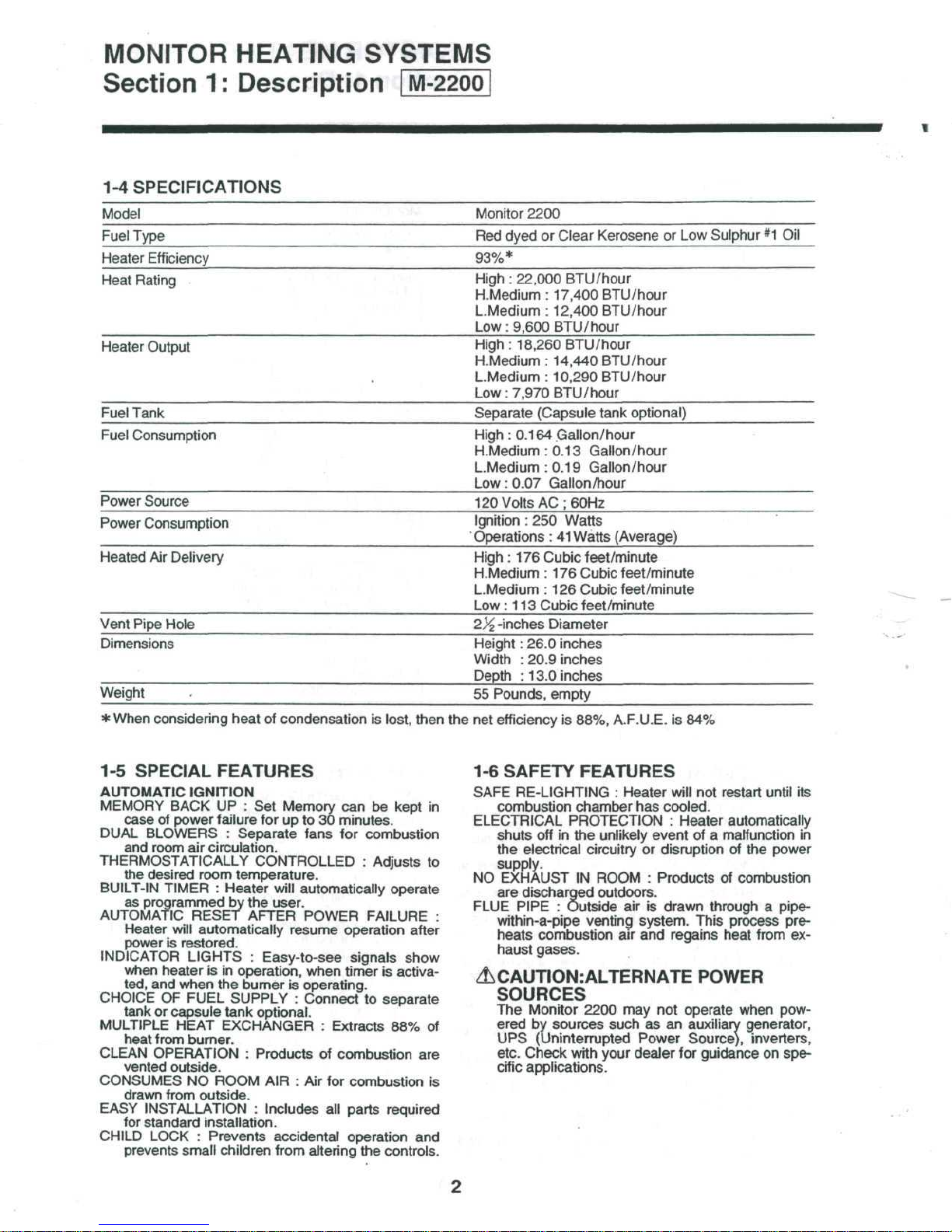
SPECIFICATIONS
Model
Fuel Type
Heater
Efficiency
Heat
Rating
Heater
Output
Fuel
Tank
Fuel Consumption
Power
Source
Power
Consumption
Heated
Air
Vent
Pipe Hole
Dimensions
Weight
*
When
1:
Delivery
considering heat
Description
of
condensation
is
lost, then
Monitor
Red
2200
dyed
or
Clear Kerosene
93%*
High : 22,000
H.Medium : 17,400
L.Medium : 12,400 BTU/hour
Low:
9,600 BTU/hour
High:
18,260 BTU/hour
H.Medium : 14,440 BTU/hour
L.Medium : 10,290 BTU/hour
Low:
7,970 BTU/hour
Separate
High:
0.164
H.Medium : 0.13 Gallon/hour
L.Medium : 0.19
Low:
0.07
120
Volts
Ignition
Operations
High : 176
H.Medium : 176
L.Medium
Low : 113
inches
Height:
Width : 20.9 inches
Depth : 13.0
55
Pounds, empty
the net
efficiency
BTU/hour
(Capsule
Gallon/hour
Gallon/hour
Gallon/hour
AC ;
60Hz
: 250
Watts
: 41
Watts (Average)
Cubic feet/minute
Cubic feet/minute
: 126
Cubic feet/minute
Cubic feet/minute
Diameter
26.0 inches
inches
is
88%, A.F.U.E.
or Low
BTU/hour
tank optional)
is 84%
Sulphur
*1 Oil
1-5
SPECIAL FEATURES
AUTOMATIC
MEMORY
case
DUAL
BLOWERS : Separate fans
and
THERMOSTATICALLY
the
BUILT-IN TIMER : Heater
as
AUTOMATIC
Heater
power
INDICATOR
when
ted,
CHOICE
tank
MULTIPLE HEAT EXCHANGER : Extracts
heat from
CLEAN
vented
CONSUMES
drawn
EASY
INSTALLATION : Includes
for
CHILD LOCK : Prevents accidental operation
prevents
IGNITION
BACK
of
room
desired room temperature.
programmed
is
heater
and
OF
or
OPERATION : Products
from outside.
standard
UP : Set
power failure
air
circulation.
by the
RESET AFTER
will
automatically resume operation after
restored.
LIGHTS : Easy-to-see
is in
when
the
FUEL SUPPLY : Connect
capsule tank
burner.
outside.
NO
RpOM
installation.
small children from
Memory
for up to 30
CONTROLLED : Adjusts
will
automatically operate
user.
POWER
operation, when timer
burner
is
optional.
AIR : Air for
operating.
of
all
altering
can be
minutes.
for
combustion
parts required
kept
combustion
FAILURE
signals
combustion
is
to
separate
88% of
the
controls.
show
activa-
and
in
to
are
is
1-6
SAFETY FEATURES
SAFE
RE-LIGHTING : Heater
combustion chamber
:
ELECTRICAL
shuts
the
supply.
NO
EXHAUST
are
FLUE
PIPE : Outside
within-a-pipe
heats
haust gases.
PROTECTION : Heater automatically
off in the
electrical circuitry
IN
discharged
venting system. This process
combustion
&CAUTION:ALTERNATE
SOURCES
The
Monitor 2200
ered
by
UPS
etc. Check with your dealer
cific applications.
sources such
(Uninterrupted
will
has
unlikely event
or
ROOM : Products
outdoors.
air is
air and
not
cooled.
of a
disruption
drawn through a pipe-
regains heat from
POWER
may not
operate when pow-
as an
Power
auxiliary generator,
Source),
for
guidance
restart
until
malfunction
of the
power
of
combustion
inverters,
on
its
in
pre-
ex-
spe-
MONITOR
HEATING SYSTEMS
Section
1:
Description
1-7
DESCRIPTION
The
Monitor heaters
are
composed
of the
following:
a
spill
tray, a cabinet, a combustion system,
an air
circulation system, a fuel delivery system, electrical
and
electronics systems
and a
variety
of
safety
mechanisms.
1-8
SPILL
TRAY
The
Spill
Tray:
—
Protects
the
floor from damage resulting from
fuel
spillage.
—
Provides a secure,
tip-resistant
heater base.
Metal retainers
(2)
secure
the
heater
to the
Spill
Tray.
The
legs
are
positioned with
in the
circular indenta-
tions.
1-9
HEATER CABINET
A
steel
cabinet
holds
and
protects
all
internal
com-
ponents.
A
number
of
primary parts
are
assembled
to
form
this
housing.
1-10 CMBUSTION SYSTEM
The
Combustion System
is
responsible
for the
pro-
duction
of
heat which
is
circulated into
the
room
.
In the
Combustion Systems a mixture
of
fuel
and air
is
burned
to
produce
heat.
Air is
drawn from outside
the
dwelling
into
the
Combustion
Chamber.
At the
same
time, fuel
is
metered
from a storage cavity into
this same Combustion Chamber.
Within
the
cham-
ber,
the
air/fuel mixture
is
ignited
to
produce heat.
The
Monitor combustion systems
are
safeguarded
by a pair
of
overheat protector switches; They
will
shut down
the
heater
(to
protect
it
from damage)
in
the
event
of
excessive heat
build-up.
The
overheat
protector
switches reset automatically after
cooling
down.
1-11 COMBUSTION CHAMBER
This
tall
cylinder
is
positioned
on the
Heater Base.
It
is
secured
to the
base
by
phillips
head screws.
Connected
to the
Combustion Chamber
are the ig-
niter, (located within
the
chamber) a fuel
line,
the
Heat
Exchanger,
and a
Flame Sensor.
Within
the
Combustion Chamber
are the
Burner Pot,
the
Combustion Ring Assembly. Access
to
those
in-
ternally-located parts
is
facilitated
by a
removable
Service
panel.
A
Window
on the
panel
lets
the
technician
visually
examine
the
combustion
process(i.e.
glowing igniter
or
proper flame color).
An
airway,
in the
Cabinet Base, extends from
the in-
take
fan of the
Combustion Blower
to the
hollow
base
of the
Combustion Chamber.
This
airway chan-
nels
air to the
Combustion Chamber.
The
Flame Sensor
is
mounted with
two (2)
phillips
head screws onto
the
wall
of the
Combustion
Cham-
ber.
1-12
BURNER
POT
Designed specifically
to
support combustion,
the
Burner
Pot
(refer
to
Figure
1-2/1-3)
contains a series
of
air
holes,
an
igniter tube
(to
accommodate
the Ig-
niter),
and a
fuel
inlet
fitting
(interconnects
the
fuel
line).
It
is
secured
to a
mounting plate near
the
bot-
tom
of the
Combustion Chamber.
The
Combustion Ring Assembly
is
seated
on
three
(3)
screws
or
pins
in the
Burner Pot.
1-13 COMBUSTION RING
ASSEMBLY
This assembly
is a
special structure, designed
to
promote efficient combustion.
1-14 FLAME
SENSOR
Mounted
on the
outside wall
of
Combustion Cham-
ber,
the
Flame Sensor always supervises
the
flame.
1-15 IGNITER
Located within
the
igniter tube
of the
Burner Pot,
the
Igniter
is
designed
to
pre-heat
the
Burner
Pot and to
vaporize
and
ignite
the
air/fuel mixture
to
start
the
combustion process.
The
Igniter
is
secured
by a
bracket
and
screw
to the
igniter tube.
The
cover plate
is
secured
to the
com-
bustion chamber
by
three
(3)
phillips
head screws.
1-16 COMBUSTION
AIR
SYSTEM
The
Combustion
Air
System channels
air to and
from
the
heater.
Outside
air is
drawn into
the
heater
by the
Combus-
tion
Blower through
an
airway
to the
Combustion
Chamber.
A
Combustion Blower draws
the
intake
air in
through a Flue Pipe. This
air
enters
the
Combustion
Chamber
at the
Burner
Pot and
mixes with
the
fuel
to
support
combustion,
Remaining
air is
heated
and
is
drawn
into
the
Heat Exchanger.
As
the
heated
air
passes through
the
Heat Exchan-
ger,
an Air
Circulation
Fan
blows room
air
past
the
Heat
Exchanger
and out
again into
the
room, heating
passing
air by
convection. Exhaust vapors
exiting
from
the
Heat Exchanger
are
vented through
the
Flue
Pipe.
A
deterioration
of air
pressure
at the Air
Pressure
Switch
is an
abnormal condition;
the
heater
is
shut
down
by the
malfunction.
MONITOR
HEATING
SYSTEMS
Section
1:
Description
1-17
FLUE
PIPE
The
Flue Pipes
is
adaptable
in
three
(3)
sizes. This
provides
the
flexibility
to
meet
the
installation
re-
quirements
for
walls
of
various thicknesses.
The
Flue Pipe
is two
Sections, Flue pipe
A and
Flue
pipeB.
The
Flue Pipe A contains a "T"-shaped
fitting con-
sisting
of
four
ports. This side
is
mounted
on the in-
terior
wall
of the
dwelling.
The
Flue Pipe
B is
vented
outside
the
dwelling.
The
Flue
Pipe
Assembly con-
sists
of two
concentric tubes. Outside
air is
drawn
through
the
cylindrical space between
the
tubes.
Combustion by-products
are
vented through
the in-
ner
tube.
As
the
cool
air
enters,
it is
heated
by the hot air
that
is
exiting
the
system.
A
large-bore,
flexible
hose connects
the air
inlet
port
on
the
Flue Pipe A with
the
Combustion Blower;
a
cloth-covered metal pipe connects
the
Combustion
Blower
with
the
exhaust outlet
on the
Flue Pipe
A.
IMPORTANT:
If
extension kits
are
utilized,
use the
correct
damper
in
accordance
with
the
instructions
in
table
2-1 of
page
14
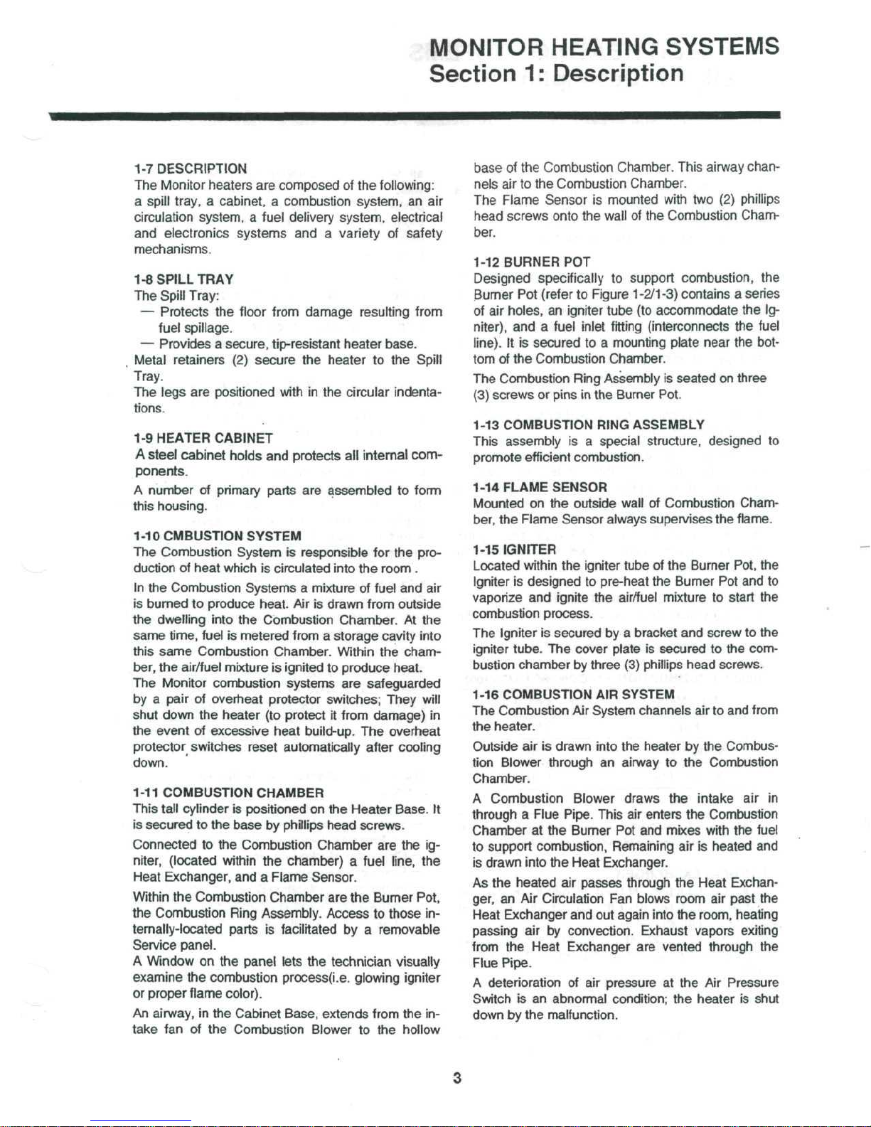
1-18 COMBUSTION
BLOWER
MOTOR
The
combustion
blower
has a
four stage intake
fan
Burner modes control
fan
speeds.
The
combustion
air
controls
are as
follows:
Table
1-1
COMBUSTION
AIR
CONTROL
(M-2400)
Burn
Mode
Fan
Speed
(r.p.m.)
High
2,800
Medium-High
2,300
Medium-Low
1,900
Low
1,500
Please refer
to
paragraph
1 -35 in
page?
for the
de-
tails
of the
combustion blower motor control.
1-19
HEAT
EXCHANGER
An
inlet
at the top of the
Heat Exchanger permits
the
heated
air to
travel from
the
Combustion Chamber
into
the
exchanger.
An
outlet,
at the
bottom
of the
exchanger, permits
combustion by-products
to be
vented
to the
Flue
Pipe.
air
within
the
exchanger heats
the
outside metal
walls.
The hot
metal walls,
in
turn, heat
air
that
is
pushed
past
the
exchanger
and is
circulated into
the
room.
An air
baffle, directly
in
front
of the
exchanger,
deflects
the
heated
air
upwards,
and
out, through
the
louver
assembly.
A
pair
of
Over-Heat Protector Switches protect
the
heater
from
damage
due to
excessive heat built-up.
1-20
AIR
CIRCULATION
FAN
Circulation fans
are
driven
by
three-speed motors
and are
designed
to
circulate
the
heated room air.
If
the
heater
is
running
in low
burn modes,
the fan
also
runs
at
low-speed;
in
medium-low burn mode,
the fan
runs
at
medium-speed;
in
medium-high
or
high burn modes,
the fan
advances
to
high speed.
Operation
of the fan is
controlled
by the
micropro-
cessor
and fan
thermostat switch.
Physically assembled with a protective wire cage
for
the
heater,
the
entire
fan
assembly
is
secured
to a
bracket
on the
rear
of the
Heater Cabinet.
A
metal conduit,
at the
rear
of the
heater, protects
the
fan
wiring from damage.
1-21
AIR
PRESSURE
SWITCH
This
switch consists
of a
rubber diaphragm which
senses
changes
in air
pressure(it
is
connected
to the
Combustion Blower)
and is a
normally open, micro
switch.
Should
an
abnormal pressure differential exist,
the
switch opens
to
disable
the
circuitry that controls
the
supply
of
fuel.
Since
the
flow
of
fuel
to the
Burner
Pot
is cut
off,
the
flame
extinguishes
(after
all
fuel
currently
in the
line
has
been consumed),
and the
code
fE14jis
indicated
in the
digital
display.
This
safety
mechanism
can be
triggered
by
several
conditions:
—
Leak
or
loose
connection
in air
line
—
Leak, loose,
or
broken
tubing
which connects
the
Air
Pressure Switch with
the
Combustion Blower
—
Clogged
or
blocked
Air
Line
—
Blocked
or
clogged Flue Pipe
—
Intake port Combustion Blower
is
blocked.
—
Combustion Blower
is
inoperable
—
Clogged
or
block
air/intake
hose.
While moving through
the
Heat Exchanger,
the hot
MONITOR HEATING SYSTEMS
Section
1:
Description
1-22
FUEL
DEUVERY
SYSTEM
Fuel
Delivery
is a
very
important
aspect
of the
Monitor's
operation.
The
fuel
flow must
be
maintained
at a
level corre-
sponding
to the
burn mode,
so
that
combustion
can
be
conducted efficiently.
Fuel moves
by
gravity-flow
from
the
external fuel
storage
tank
or the
capsule fuel tank
to the
Fuel
Constant Level Valve.
The
Solenoid Pump meters
the
flow
of
fuel from
the
Fuel Constant Level Valve
to the
Burner Pot.
The
metered flow
of
fuel
is
carried
to the
Burner
Pot
by a copper fuel
line.
1-23
EXTERNAL
FUEL TANK
Fuel
for the
Monitors
can be
stored
in,
and fed
from
an
external storage
tank.
The
tank,
which generally
is
dealer
installed,
should
contain a shutoff
valve,
a
fuel
filter
and a
vent.
Installation
of the
tank should
conform
to
local
regulations
and to the
specifica-
tions
and
guidelines
documented
in
this
Service
Manual.
1-24 FUSIBLE LINK
VALVE
Basically,
the
Fusible Link Valve
is a
safety mecha-
nism that
cuts-off
fuel
to the
heater
in the
event
of
an
overheat
condition
at the
valve.
In
M-2400/M-2200,
Fusible
Link
Valve
is not
instal-
led,
If
necessary,
it can be
installed
outside
of the
appliance.
The
Fusible Link Valve
is a
springloaded
device that
cuts
off the
supply
of
fuel
to the
heater when
the
temperature level
(at the
valve)
exceeds a predefined maximum
limit.
An
inlet
on the
bottom
of the
valve
allows
fuel
to
pass
into
the
heater.
The
handle-which
can
also
manually
be
opened
or
closed-sits
on a
springloaded stem which contains a low-melting point
alloy.
Fuel
enters
the
Fuel Constant
Level
Valve
through
an
inlet
at the
bottom
of the
reservoir.
As the
level
of
fuel rises,
it
passes through a filter (which
removes
most
particles
and
foreign matter
from
the
fuel),
flows
up
through
an
open inlet valve
and
enters
the
tank.
IMPORTANT:
The
Fuel
Constant
Level
Valve
filter
should
be
cleaned
or
replaced peri-
odically.
Time
intervals
will depend
on
purity
and
quality
of
fuel.
Within
the
Valve, a float mechanism controls
the
level
of
fuel that will
be
permitted
to the
reservoir.
As
the
fuel level drops,
the
float drops down
to
increase
the
inlet
valve opening
to
admit
more
fuel
into
the
valve.
When
the
fuel level reaches
its
maximum
volume,
the
float
rises
to
shut
the
inlet valve.
In the
event
that
fuel
within
the
reservoir
rises
to an
abnormally high level, a float within
the
reservoir
rises
to
trip a safety magnet. This safety magnet
locks
out the
float
to
prevent fuel from entering
in the
reservoir.
Should a foreign substance cause
the
inlet
valve
to
stick
(or
prevent
it
from opening),
the
Fuel
Set
Lever
is
utilized
to
free
the
valve
and to
admit fuel
to the
reservoir.
A
CAUTION:
Care
must
be
taken
to
prevent
dust,
dirt,
or
other debris from
clogging
or
blocking
the
inlet
valve.
If
debris collects
on the
seat
of the
inlet
valve
it may
cause
tripping
of the
safety
lever
and
will
require cleaning.
1-25
FUEL
CONSTANT
LEVEL
VALVE
This valve
has an
automatic shutoff safety mecha-
nism
and a
Fuel
Set
Lever.
The
safety mechanism
prevents
fuel from flooding
or
overflowing
from
the
fuel
reservoir.
The
Fuel
Set
Lever resets
the
float
so
the
Fuel Constant Level Valve
can
resume opera-
tion.
The
fuel reservoir
is a
tank which contains a float
assembly, a safety mechanism,
and a
priming lever.
MONITOR HEATING SYSTEMS
Section
1:
Description
1-26
SOLENOID
PUMP
The
Solenoid Pump, mounted
on the
Fuel
Constant
Level
Valve,
and
controlled
by a
microprocessor,
delivers
four
fuel flow modes (High, Medium-High,
Medium-Low,
Low)
to the
Burner Pot.
1-27
ELECTRICAL
SYSTEM
Electrical
power
is
supplied
to the
Monitor
to run the
Microprocessor
and the
other
electrically-energized
component.
Electrical operation
of the
Monitor
can be
thought
of
as
having
the
following
eight(8)
distinct
phases.plug
in;
turn-on;
pre-purge/pre-heat;
ignition; pre-
combustion;
heating;
Shutdown
and
post-purge.
All
electronic diagrams, Such
as
wiring diagram,
circuit
board layout,
and
electrical
schematic
can be
found
in
Section
7 of
this Service Manual.
1-28
MICROPROCESSOR
Principally consisting
of a
64-pin
Integrated
Circuit,
the
Microprocessor provides safety timings, controls
relays
and
provides
clock
and
thermostat functions
for
the
Monitor heater. A component layout
of the
Printed
Circuit Board
is
found
in
Section
7 of
this
Service
Manual.
1-29
TEMPERATURE
SENSOR
The
sensor
which
is
capable
of
sensing
room
tem-
perature
within a range
of
42"F
to
96°F,
can be
left
mounted
on the
back
of the
heater cabinet
or be
wall mounted.
Approximately
4/^'(about
140 cm) of No. 22 AWG
Wire
is
supplied with
the
sensor
to
facilitate wall
mounting
the
sensor
in a
favorable location.
1-30
SAFETY
MECHANISMS
Several
safety mechanisms have been built into
the
Monitor
Heating System. These devices protect
the
user
against personal
injury,
protect
the
heater
against
damage,
and
shutdown
the
heater
if a
malfunction occurs.
During
installation make
sure
that
all
Exhaust
Lines
are
tight.
Do not
operate
the
heater
without
the
insulating covers.
1-32
AIR
CIRCULATION
FAN
GUARD
This guard
is an
integral
part
of the fan
assembly.
The
guard protects
the
user
against physical injury
which could occur
from
accidental contact with
revolving
metal
fan
blade.
1-33
FUSE
2-amp.
and
10-amp.,
125VAC,
fuses protect
the
heater
from
damage resulting
from
power overloads.
In
the
event
of a
power surge
or
internal wiring
hazards,
the
fuse
opens
and
power
to the
heater
is
cut
off.
The
electrical outlet into which
the
heater
is
con-
nected should
be
protected
by at
least a 15-amp.
fuse
or
circuit breaker.
1-34
OVERHEAT PROTECTOR
SWITCHES
(M-2400)
Connected
in
series,
two (2)
normally-closed Over-
heat
Protector Switches safeguard
the
heaters
against damage
due to
overheating.
The
switches
are
rated
115'C
(239'F).
Should
a
Monitor overheat (internal temperatures
rise
beyond
115'C
(239'F)). either
or
both switches will open
to
shut down
the
heater.
After
extinguishing
the
flame,
the
code
FE14J
is
indicated
in the
digital display.
The
Overheat Protector Switches
will
automatically
reset
after
cooling down.
Once
the
heater
has
cooled
to
90'C
(194*F),
the
system
can be
restarted.
To
restart
the
Monitor,
proceed
as
follows:
A.
Press ON/OFF Switch
to
OFF.
B.
Allow heater
to
cool.
C.
Troubleshoot
the
cause
of the
overheat.
D.
Press
ON/OFF switch
to ON
E.
Proceed with normal operation.
1-31
CLOTH COVERED EXHAUST
PIPE
Insulating cloth covers
are to be
placed
over
all
metal surfaces
of the
Exhaust
Line
during
installa-
tion.
Since
combustion by-products
are
vented
at
ele-
vated
temperatures,
the
Exhaust Pipe will become
hot
during operation.
The
insulating
cloth
covers
protect
the
user from burn hazards associated with
accidental contact with these heated metal surfaces.
6
MONITOR
HEATING SYSTEMS
Section
1:
Description
1-35
Revolution
control
of
combustion
blower
motor
IC4
TRIAC L fSfj
1
Hole
1C
01
JT
Fig.
1-1
-o
5V
microprocessor
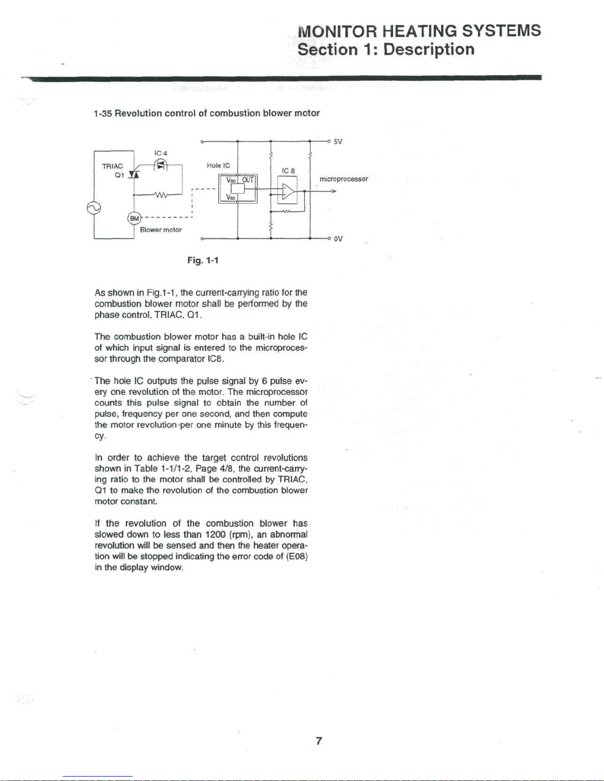
As
shown
in
Fig.1-1,
the
current-carrying
ratio
for the
combustion blower motor shall
be
performed
by the
phase
control,
TRIAC,
Q1.
The
combustion blower motor
has a
built-in
hole
1C
of
which input signal
is
entered
to the
microproces-
sor
through
the
comparator IC8.
The
hole
1C
outputs
the
pulse signal
by 6
pulse
ev-
ery
one
revolution
of the
motor.
The
microprocessor
counts this pulse
signal
to
obtain
the
number
of
pulse, frequency
per one
second,
and
then compute
the
motor
revolution
-per
one
minute
by
this
frequen-
cy.
In
order
to
achieve
the
target control revolutions
shown
in
Table 1-1/1-2, Page 4/8,
the
current-carry-
ing
ratio
to the
motor shall
be
controlled
by
TRIAC,
Q1
to
make
the
revolution
of the
combustion blower
motor
constant.
If
the
revolution
of the
combustion blower
has
slowed down
to
less than 1200
(rpm),
an
abnormal
revolution
will
be
sensed
and
then
the
heater opera-
tion
will
be
stopped
indicating
the
error code
of
(EOS)
in the
display window.
MONITOR
HEATING SYSTEMS
Section
1:
Description
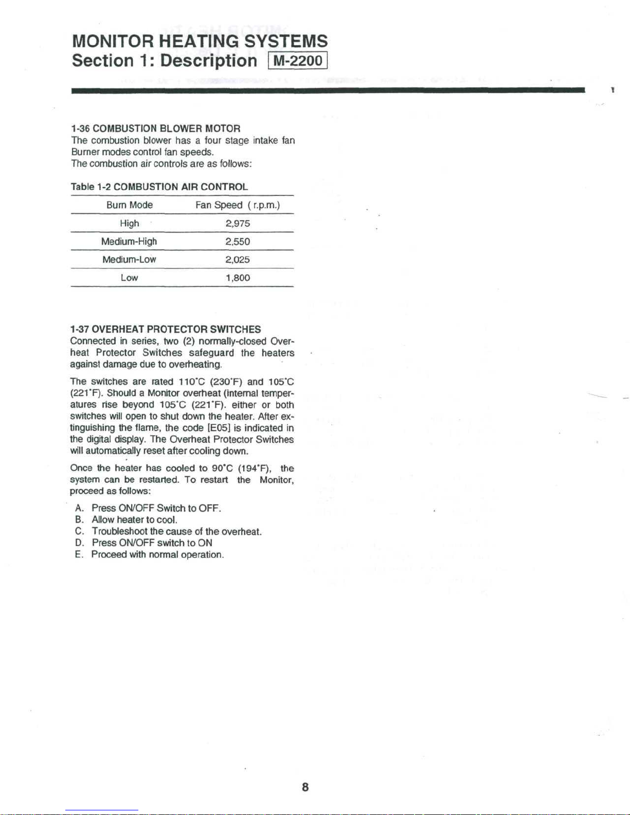
1-36
COMBUSTION
BLOWER
MOTOR
The
combustion blower
has a
four stage intake
fan
Burner
modes control
fan
speeds.
The
combustion
air
controls
are as
follows:
Table
1-2
COMBUSTION
AIR
CONTROL
Burn
Mode
Fan
Speed
(r.p.m.)
High 2,975
Medium-High
2,550
Medium-Low 2,025
Low
1,800
1-37
OVERHEAT
PROTECTOR
SWITCHES
Connected
in
series,
two (2)
normally-closed
Over-
heat
Protector Switches safeguard
the
heaters
against damage
due to
overheating.
The
switches
are
rated
110'C
(230T)
and
105'C
(221
'F).
Should a Monitor overheat
(internal
temper-
atures
rise
beyond 105'C
(221'F).
either
or
both
switches
will
open
to
shut down
the
heater.
After
ex-
tinguishing
the
flame,
the
code
[EOS]
is
indicated
in
the
digital
display.
The
Overheat Protector Switches
will
automatically reset after
cooling
down.
Once
the
heater
has
cooled
to
90'C
(194T),
the
system
can be
restarted.
To
restart
the
Monitor,
proceed
as
follows:
A.
Press ON/OFF Switch
to
OFF.
B.
Allow heater
to
cool.
C.
Troubleshoot
the
cause
of the
overheat.
D.
Press
ON/OFF
switch
to ON
E.
Proceed with normal
operation.
8
MONITOR HEATING SYSTEMS
Section
1:
Description
UJ
en
z
o
CO
m
S.
o
o
LL
O
CO
UJ
UJ
2
9
MONITOR HEATING SYSTEMS
Section
1:
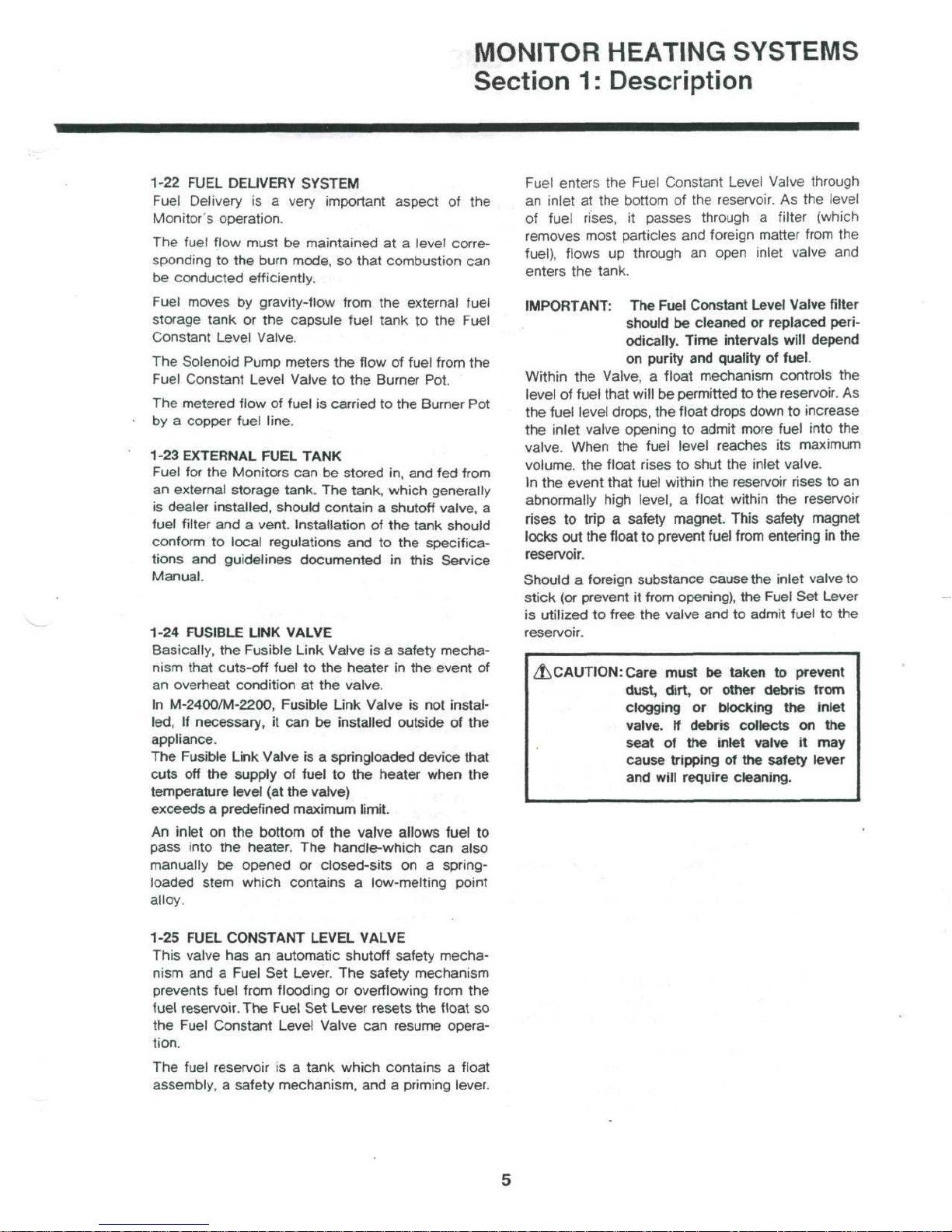
Description | M-2200
AIR
CIRCULATION
FAN
FLAME
SENSOR
FLUE PIPE
COMBUSTION RING
BURNER
POT
^•^U^-S
CAPSULE EXTERNAL
FUEL
TANK
FUEL
TANK
\CONSTANT
LEVEL
VALVE
AIR
PRESSURE
SWITCH
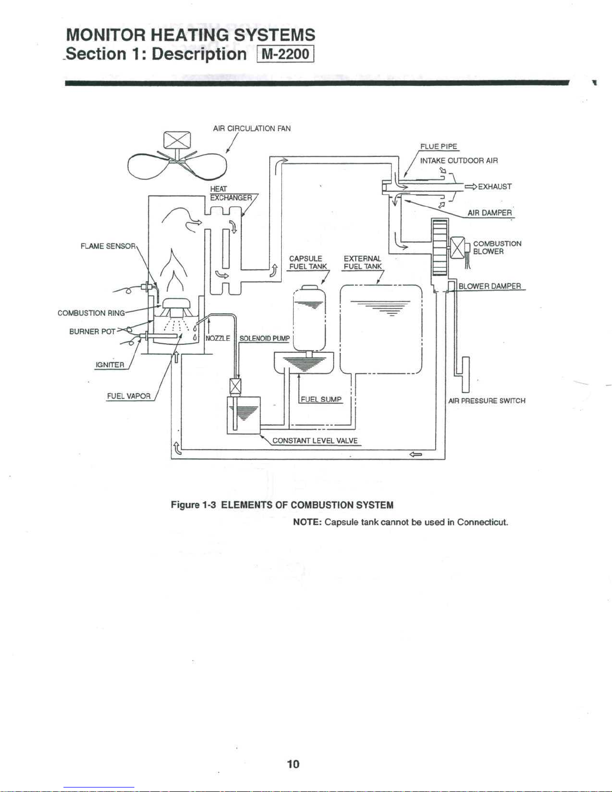
Figure
1-3
ELEMENTS
OF
COMBUSTION
SYSTEM
NOTE:
Capsule tank cannot
be
used
in
Connecticut.
10

MONITOR
HEATING
SYSTEMS
Section
2:
Installation
2-1
INTRODUCTION
Installing
the
Monitor
System
at the
user's
location
can
be
performed
quickly
and
economically.
The
Monitor
2400/2200 model
is
strictly a remotely
fueled
system
and is
externally vented.
As
such
it
needs
the
installation
of an
externally vented
intake/
exhaust
system
and if
remotely
fueled,
will
need
the
installation
of a
remote fuel storage tank.
By
completing each step
of the
easy-to-follow
installation
instructions
(each step should
be
com-
pleted
in the
exact order
specified),
the
Technician
is
directed through
the
installation
process.
This section
contains
all
relevant
installation
infor-
mation
including:
—
Installation
specifications
—
List
of
installation
tools
—
Alternative types
of
venting systems (and
in-
stallation
procedures
for
each)
—
Basic requirements
for
fuel
tank
installation
—
Instructions
to
install
the
Monitor
System
IMPORTANT:
Before
beginning installation
of the
Monitor
vented
heating
system
(in-
cluding
any
electrical
wiring
and
fuel
supply
equipment), check local
building,electrical,
mechanical
and
fire
codes.
The
requirements
of
these
codes
must
be
followed
to
insure
lawful installation
and
use.
The
heater
can be
located
almost anywhere within
the
dwelling provided
that
electrical,
fuel,
and ex-
haust
specifications
are
met.
2-2
PHYSICAL PLACEMENT
OF
HEATER
In
addition
to the
space
taken
up by the
heater,
interior space must also
be
reserved
for
free
air
circulation.
Remove
all
combustibles
from
the
heat-
ing
area.
Unless
building
or
fire codes
dictate
otherwise,
the
Monitor system
can be
placed
on any
floor surface
(including
carpeting
or
other combustible material)
and
provide safe
operation.
2-3
DRILLING REQUIREMENTS
Through-the-wall
Flue Pipe
installation
requires that
a 2
Vz"
(65mm)
hole
be
drilled
through
the
dwelling
wall (interior
to
exterior).
The
hole must
be
pitched
downward
toward
the
outside
at an
approximate
angle
of
2"(about l/2"
per
foot).
The
appropriate
wall
area
(in
which hole
will
be
drilled)
must
contain
no
internal
obstacles
such
as
piping,
wiring,
air
ducts,
or
studs.
RECOMMENDED
TOOL
KIT FOR
MONITOR
HEATER
SERVICE
TECHNICIANS
1)
#2
Phillips
Head
Screwdriver
2)
Steel Tape Measure
3)
Felt
Tip Pen or
Pencil
4)
Caulking
Material (exterior
grade)
5)
Electrical Drill
(reverse
capability
recommended)
6)
Hole Saw, Saber (Jig) Saw,
or
other appropriate
tool
for
cutting a 2.5" diameter hole
for
flue pipe
7)
Rubber Clipping Tool
8)
Long
Drill
Bit—'//'
9)
#2
Standard Screwdriver
10)
Adjustable Wrenches
(various
sizes)
11)
Copper Tubing Cutter
12)
Copper Tubing Flaring Tool
13)
V.O.M.(Volt.
OHM. Meter with shielded
probes)
14)
Level
15)
Plumber's
Pipe Thread Tape
16)
Small assortment
of
Self-Tappeng
Screws
17)
Assorted Pliers (Slip
Joint,
Needlenose, Cutting,
Lock
Joint)
18)
Phenolic
Probe
or
Insulated
Screwdriver
19)
Supply
of
125V,
2 and 10 Amp
fuses
20)
Floor
mat to
cover
carpeting
21)
Quart size
pan for
draining fuel
2-4
POWER
REQUIREMENTS
WARNING:
THE
MONITOR
POWER
CORD
MUST
BE
PLUGGED
INTO A DIRECTLY ACCESSIBLE
WALL
OUTLET.
DO
NOT USE AN
EXTENSION
CORD
TO
MAKE
THIS
ELECTRICAL CONNECTION.
Line
current
to the
system
should
be 120 VAC at 60
Hz.
The
electrical
system should
be
protected
against
current
overload
by
means
of at
least
a
15-ampere
fuse
or
circuit
breaker.
NOTE:
The
wall
outlet
should supply electricity
for
the
Monitor system only.
Do not
connect
any
other
electrical
appliance
to it.
^CAUTION:
In
some installations,
it may be
best
to
hard-wire
the
heater
to the
house
circuits. A competent,
licensed electrician
should
do
this.
11

MONITOR
HEATING SYSTEMS
Section
2-5
FUEL
2:
TANK
REQUIREMENTS
Installation
WARNING:
INSTALLATION
FUEL
TANKS
STANDARDS
Heater
fuel (crystal clear kerosene only)
stored
in
from
55
gallon drums
using
large tanks a pressure regulator with a max.
2.5
PSI
should
(if top of
unit.)
/JK.CAUTION:
2-6
TEMPERATURE
MENTS
A
wall-mounted temperature Sensor gauges
temperature
cycles
of the
The
standard sensor wire
left mounted
If
this
is not
a
wall.
OF ANY
MUST
AND/OR
remotely located storage tanks ranging
be
installed near heater
tank
is
going
In
some
ter to
plumbing. A licensed plumber
oil
dealer should
and
automatically regulates
Monitor System.
on the
practical
REMOTELY
COMPLY
BUILDING CODES.
to 275
to be
installations,
install permanent
SENSOR
back
the
WITH
gallon tanks. When
8'
higher
do
WIRING
is
4/£'
long
of the
cabinet
sensor
can be
LOCATED
ALL
inlet,
than
it may be
fuel
this.
REQUIRE-
the
and can be
as
mounted
LOCAL
can be
base
of
bet-
tank
or
room
heating
shipped.
on
of
NOTE:
The
tion
return
as
possible.
D.
Remove
remove
E.
Remove
F.
Remove
parts.and
G.
Remove
heater.
H.
Firmly
of
board
I.
Check
Guide.
IMPORTANT:
the
When
Pipe
from cardboard packing materials.
grasp cabinet
heater cabinet)
shipping base.
for
Dealer should complete
Card
at
time
of
customer
it to
Monitor
the
spill
plastic bag.
the
plastic
the
plastic
set it
aside.
the
Flue Pipe from
ready
parts
Only
is
shipped with
Monitor
longer
pipe, Window Kits, Extension
Kits,
may
be
installations.
Products, Inc.
tray
from
bag
covering
bag
containing
to
install, separate Flue
handles
and
lift
heater
as
listed
the
standard-size Flue Pipe
dealer
Flue pipe
and
other accessories that
required
the
purchase
shipping
the
(one
in
Monitor
the
will
also stock
B and a
for
non-standard
Registra-
as
carton,
the
heater.
the
rear
of
each side
off the
Owners
heater.
and
soon
and
heater
of the
card-
The
a
Relay
il\CAUTION:
2-7
BUILDING CODES
Fire regulations,
codes
may
vented heater
installation,
2-8
UNPACKING
Save
all
been completely
A.
Cut the
ping carton together.
B.
Remove
C.
Remove
(drilling) Template
If
,
motely
direct
exterior
as
temperature
electrical
govern
and
check
shipping
three plastic
the
from
sensor
installed
top.
is to be
be
careful
sunlight,
walls
in
this will create
reading.
and
the
installation
related
and
materials
the
fueling
comply
until
and is
ribbons
shipping carton
and the
on
drafty
other
with
Owner's
mounted
not to
uninsulated
areas etc.,
an
inaccurate
local
and use of a
systems. Prior
all
the
Monitor
working properly.
that hold
the
re-
place
it in
building
codes.
the
Cardboard
'Guide.
has
ship-
to
12
MONITOR
HEATING SYSTEMS
Section
2:
Installation
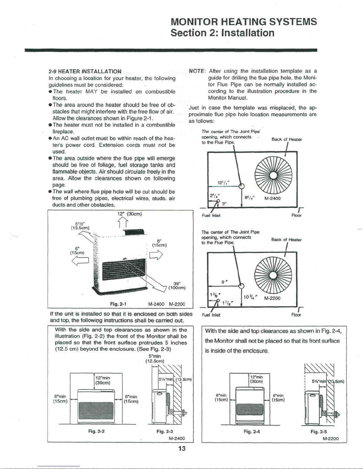
2-9
HEATER INSTALLATION
In
choosing a location
for
your
heater,
the
following
guidelines
must
be
considered:
•
The
heater
MAY be
installed
on
combustible
floors.
•
The
area
around
the
heater should
be
free
of ob-
stacles that might interfere
with
the
free flow
of
air.
Allow
the
clearances shown
in
Figure
2-1.
•
The
heater must
not be
installed
in a
combustible
fireplace.
• An AC
wall outlet must
be
within reach
of the
hea-
ter's
power cord. Extension cords must
not be
used.
•
The
area outside where
the
flue
pipe
will
emerge
should
be
free
of
foliage, fuel storage tanks
and
flammable
objects.
Air
should
circulate
freely
in the
area.
Allow
the
clearances shown
on
following
page.
•
The
wall where
flue
pipe
hole
will
be cut
should
be
free
of
plumbing pipes, electrical wires,
studs,
air
ducts
and
other obstacles.
NOTE: After
using
the
installation
template
as a
guide
for
drilling
the
flue pipe hole,
the
Moni-
tor
Flue Pipe
can be
normally installed
ac-
cording
to the
illustration
procedure
in the
Monitor
Manual.
Just
in
case
the
template
was
misplaced,
the
ap-
proximate
flue pipe hole location measurements
are
as
follows:
12"
(30cm)
5V2"
(13.5cm)
Fig.
2-1
39"
(100cm)
M-2400
M-2200
If
the
unit
is
installed
so
that
it is
enclosed
on
both
sides
and
top,
the
following
instructions
shall
be
carried
out.
With
the
side
and top
clearances
as
shown
in the
illustration
(Fig.
2-2)
the
front
of the
Monitor
shall
be
placed
so
that
the
front surface protrudes 5 inches
(12.5
cm)
beyond
the
enclosure.
(See
Rg.
2-3)
5"min
(12.5cm)
(13.5cm)
6"min
(15cm)
6"min
(15cm)
Rg. 2-2
Fig.
2-3
M-2400
13
The
center
of The
Joint
Pipe'
opening,
which
connects
to
the
Flue
Pipe.
Back
of
Heater
The
center
of The
Joint
Pipe
opening,
which
connects
to
the
Flue
Pipe.
Back
of
Heater
With
the
side
and top
clearances
as
shown
in
Fig.
2-4,
the
Monitor
shall
not be
placed
so
that
its
front surface
is
inside
of the
enclosure.
6"min
(15cm)
.115cm)
6'min
(15cm)
Fig.
2-4
Fig.
2-5
M-2200

MONITOR
HEATING
SYSTEMS
Section
2:
Installation
Table
2-1
Installation
Classification
for
using
Damper
Diameter
and
Processing
of
P.W.B.
Jumper
Wire
CJ
Installation
Classification
Up
to 1
bend(90°elbows) with
no
extension
Up
to 1
bend(90'elbows)
with
extension
kit
length : 0-73"
2
bends with extension
kit
length
:
exceed
20" or 3
bends
P.W.B.
Jumper Wire
CJ
Altitude (feet)
0~3,000
Air
Damper
STANDARD
Used
EXTENSION
Used
Blower
Damper
Used
Used
No
Cut
3,000—5,000
Air
Damper
STANDARD
Used
Not
Used
Not
Used
Blower
Damper
Used
Used
Not
Used
5,000-7,000
Air
Damper
EXTENSION
Used
Not
Used
Blower
Damper
Used
Not
Used
THIS
UNIT
CAN NOT BE
USED
FOR
THIS
APPLICATION.
Cut
The
blower
damper
is fixed
with
suction
case
B of
the
combustion
blower
ass'y,
as
shown
in
Fig.
2-6.
To
remove
the
blower
damper
from
suction
case
B,
remove
the air
hose
supply
ass'y,
first and
then
loosen
the
screw
holding
the
blower
damper.
After
the
blower
damper
has
been
removed,
insert
air
supply hose
ass'y
into
the
suction
case
B and
tighten
by the
hose
band.
Suction
case
B
Combustion blower assy
Blower damper
Hose band
Screw
Air
supply hose assy
[Position
of
P.W.B. jumper wire
CJ and
reset
push-
button switch]
Reset
push-button
-
switch
^
Jumper wire
CJ
D
P.W.B.
IMPORTANT:
After
cutting
the
jumper wire
CJ,
please
be
sure
to
press
the
reset push-button switch
on the
P.W.B.
two
to
three
times,
with
the
power
plug
inserted
in
the
socket.
If
the
reset button
has
been pressed, settings such
as
the
current
time,
current
day of the
week,
economy
plus
and
child lock
functions
will
be
cancelled,
and
these programs must
be set
again.
Fig.
2-6
14
MONITOR
HEATING SYSTEMS
Section
2:
Installation
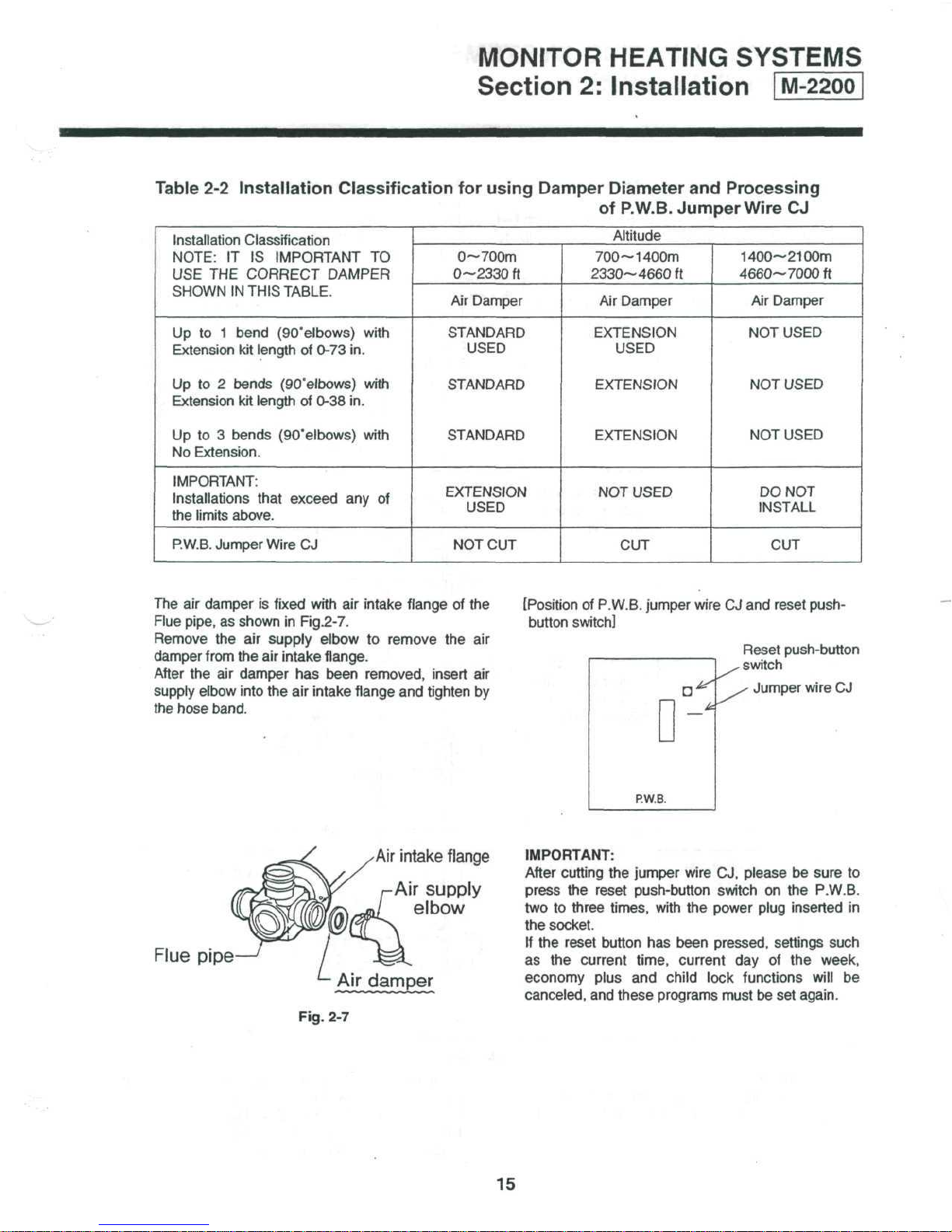
Table
2-2
Installation Classification
for
using Damper Diameter
and
Processing
of
P.W.B.
Jumper Wire
CJ
Installation Classification
NOTE:
IT IS
IMPORTANT
TO
USE THE
CORRECT DAMPER
SHOWN
IN
THIS TABLE.
Up
to 1
bend
(90'elbows)
with
Extension
kit
length
of
0-73
in.
Up
to 2
bends
(90°elbows)
with
Extension
kit
length
of
0-38
in.
Up
to 3
bends
(90'elbows)
with
No
Extension.
IMPORTANT:
Installations
that exceed
any of
the
limits
above.
P.W.B.
Jumper Wire
CJ
Altitude
0~700m
0—2330
ft
Air
Damper
STANDARD
USED
STANDARD
STANDARD
EXTENSION
USED
NOT
CUT
700—
1400m
2330—
4660ft
Air
Damper
EXTENSION
USED
EXTENSION
EXTENSION
NOT
USED
CUT
1400—
2100m
4660—
7000ft
Air
Damper
NOT
USED
NOT
USED
NOT
USED
DO
NOT
INSTALL
CUT
The
air
damper
is
fixed
with
air
intake
flange
of the
Flue pipe,
as
shown
in
Fig.2-7.
Remove
the air
supply
elbow
to
remove
the air
damper
from
the air
intake
flange.
After
the air
damper
has
been removed, insert
air
supply elbow into
the air
intake flange
and
tighten
by
the
hose band.
[Position
of
P.W.B. jumper wire
CJ and
reset push-
button switch]
Reset
push-button
.
switch
^
Jumper wire
CJ
D'
o-
P.W.B.
Flue
pipe
Air
intake
flange
Air
supply
elbow
A|r
damper
Fig.
2-7
IMPORTANT:
After
cutting
the
jumper wire
CJ,
please
be
sure
to
press
the
reset push-button switch
on the
P.W.B.
two
to
three times, with
the
power plug inserted
in
the
socket.
If
the
reset button
has
been pressed, settings such
as
the
current
time,
current
day of the
week,
economy plus
and
child
lock functions
will
be
canceled,
and
these programs must
be set
again.
15
MONITOR HEATING SYSTEMS
Section
2:
Installation
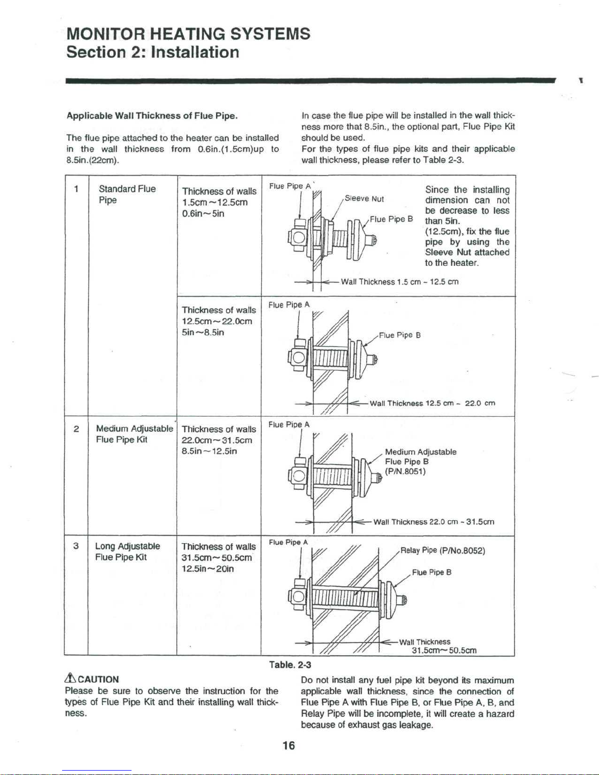
Applicable
Wall
Thickness
of
Flue Pipe.
The
flue
pipe
attached
to the
heater
can be
installed
in the
wall thickness from
0.6in.(1.5cm)up
to
8.5in.(22cm).
In
case
the
flue pipe will
be
installed
in the
wall thick-
ness
more
that
8.5in.,
the
optional part, Flue Pipe
Kit
should
be
used.
For
the
types
of
flue pipe kits
and
their applicable
wall
thickness, please
refer
to
Table 2-3.
Standard
Flue
Pipe
Thickness
of
walls
1.5cm ~ 12.5cm
0.6in~5in
Thickness
of
walls
12.5cm~22.0cm
Sin
~8.5in
Flue
Pipe
A
,Sleeve
Nut
nrK
/Flue
Pipe
B
Since
the
installing
dimension
can not
be
decrease
to
less
than
Sin.
(12.5cm),
fix
the
flue
pipe
by
using
the
Sleeve
Nut
attached
to
the
heater.
s—
Wall Thickness
1.5
cm -
12.5
cm
Flue Pipe
A
Flue Pipe
B
y/\<Z.
Wall Thickness
12.5
cm -
22.0
cm
Medium
Adjustable
Flue
Pipe
Kit
Thickness
of
walls
22.0cm~31.5cm
8.5in~12.5in
Flue
Pipe
A
A
Medium
Adjustable
Flue
Pipe
B
(P/N.8051)
s£r-
Wall Thickness 22.0
cm -
31.5cm
Long
Adjustable
Flue Pipe
Kit
Thickness
of
walls
31.5cm ~ 50.5cm
12.5in~20in
Flue
Pipe
A
Relay
Pipe
(P/No.8052)
Flue Pipe
B
Wall Thickness
31.5cm~
50.5cm
Table.
2-3
A
CAUTION
Please
be
sure
to
observe
the
instruction
for the
types
of
Flue
Pipe
Kit and
their
installing
wall
thick-
ness.
Do
not
install
any
fuel pipe
kit
beyond
its
maximum
applicable wall thickness, since
the
connection
of
Flue
Pipe A with
Flue
Pipe
B, or
Flue
Pipe
A, B, and
Relay
Pipe
will
be
incomplete,
it
will
create a hazard
because
of
exhaust
gas
leakage.
16
MONITOR
HEATING
SYSTEMS
Section
2:
Installation
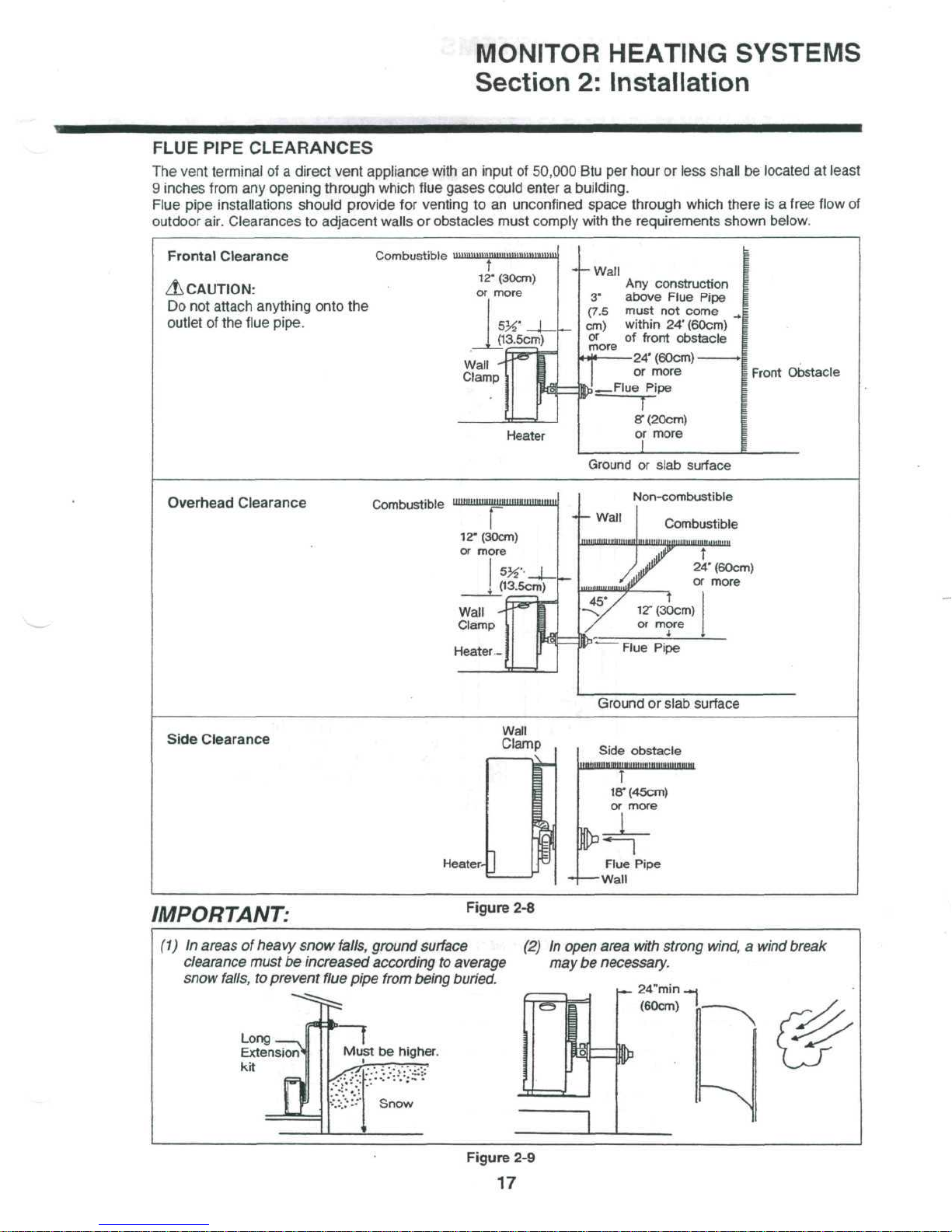
FLUE
PIPE
CLEARANCES
The
vent terminal
of a
direct
vent appliance with
an
input
of
50,000
Btu per
hour
or
less
shall
be
located
at
least
9
inches from
any
opening
through
which flue gases could enter a building.
Flue pipe installations
should
provide
for
venting
to an
unconfined space through which there
is a
free
flow
of
outdoor
air. Clearances
to
adjacent walls
or
obstacles must comply with
the
requirements shown below.
Frontal
Clearance
Combustible
iiiiniiiiminimiiinintiiniiniiii
12"
(30cm)
A
CAUTION:
or
more
Do
not
attach anything onto
the
outlet
of the
flue
pipe.
J13.5cm)
Wall
-
Clamp
-f-Wall
Any
construction
3"
above
Flue Pipe
(7.5
must
not
come
cm)
within
24'(60cm)
or
of
front obstacle
-24'(60cm)
or
more
i-—Flue
Pipe
~T~
8T(20cm)
or
more
more
I
Front
Obstacle
Ground
or
slab
surface
Overhead
Clearance
Combustible
Non-combustible
Ground
or
slab
surface
Side Clearance
Wall
Clamp
Heater-
Side
obstacle
T
18"
(45cm)
or
more
Flue
Pipe
-Wall
IMPORTANT:
Figure
2-8
(1) In
areas
of
heavy
snow
falls,
ground
surface
(2) In
open area
with
strong
wind, a wind
break
clearance
must
be
increased according
to
average
may be
necessary,
snow
falls,
to
prevent
flue
pipe
from
being buried.
Long
Extension
kit
u»-
=»
24"min
.
(60cm)
Figure
2-9
17
MONITOR
HEATING SYSTEMS
Section
2:
Installation
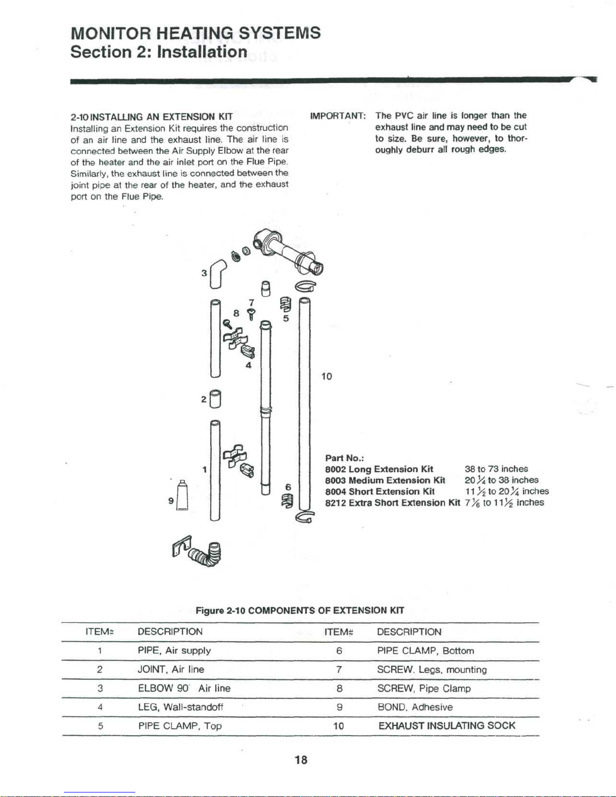
2-10 INSTALLING
AN
EXTENSION
KIT
Installing
an
Extension
Kit
requires
the
construction
of
an air
line
and the
exhaust
line.
The air
line
is
connected between
the Air
Supply Elbow
at the
rear
of
the
heater
and the air
inlet port
on the
Flue
Pipe.
Similarly,
the
exhaust
line
is
connected
between
the
joint pipe
at the
rear
of the
heater,
and the
exhaust
port
on the
Flue Pipe.
IMPORTANT:
The PVC air
line
is
longer
than
the
exhaust
line
and may
need
to be cut
to
size.
Be
sure,
however,
to
thor-
oughly
deburr
all
rough
edges.
10
Part
No.:
8002 Long Extension
Kit 38 to 73
inches
8003 Medium Extension
Kit
20
^A,
to 38
inches
8004 Short Extension
Kit
11
>£
to
20
>J
inches
8212
Extra Short Extension
Kit
7^
to
1l)i
inches
Figure
2-10 COMPONENTS
OF
EXTENSION
KIT
ITEM?
DESCRIPTION
1
PIPE,
Air
supply
2
JOINT,
Air
line
3
ELBOW
90
Air
line
4
LEG,
Wall-standoff
5
PIPE
CLAMP,
Top
ITEM;
6
7
8
9
10
DESCRIPTION
PIPE
CLAMP,
Bottom
SCREW.
Legs,
mounting
SCREW,
Pipe
Clamp
BOND. Adhesive
EXHAUST
INSULATING
SOCK
18
MONITOR HEATING SYSTEMS
Section
2:
Installation
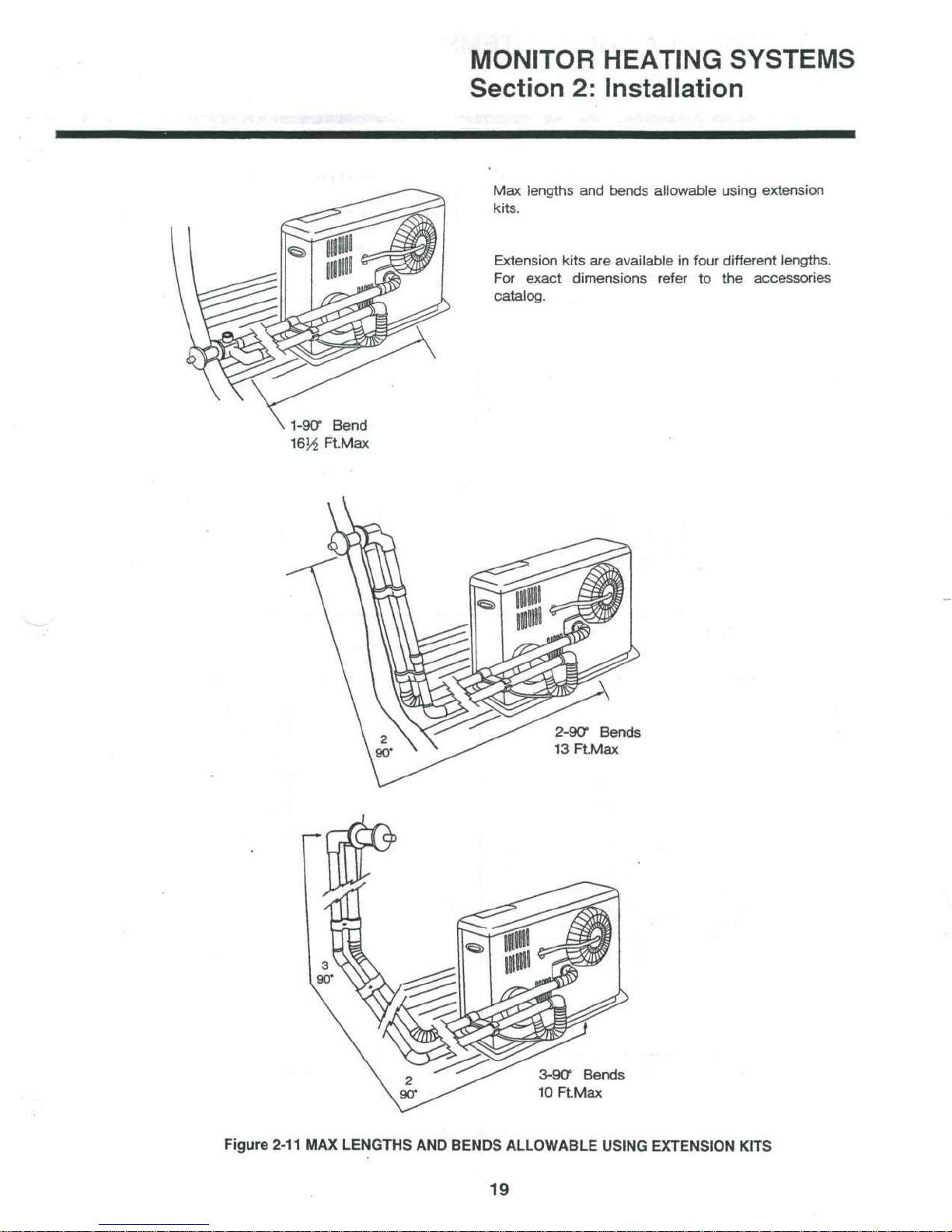
Max
lengths
and
bends
allowable
using extension
kits.
Extension
kits
are
available
in
four different
lengths.
For
exact
dimensions
refer
to the
accessories
catalog.
1-90° Bend
FtMax
3-90°
Bends
10
FtMax
Figure
2-11
MAX
LENGTHS
AND
BENDS
ALLOWABLE
USING EXTENSION KITS
19
MONITOR
HEATING SYSTEMS
Section
2:
Installation
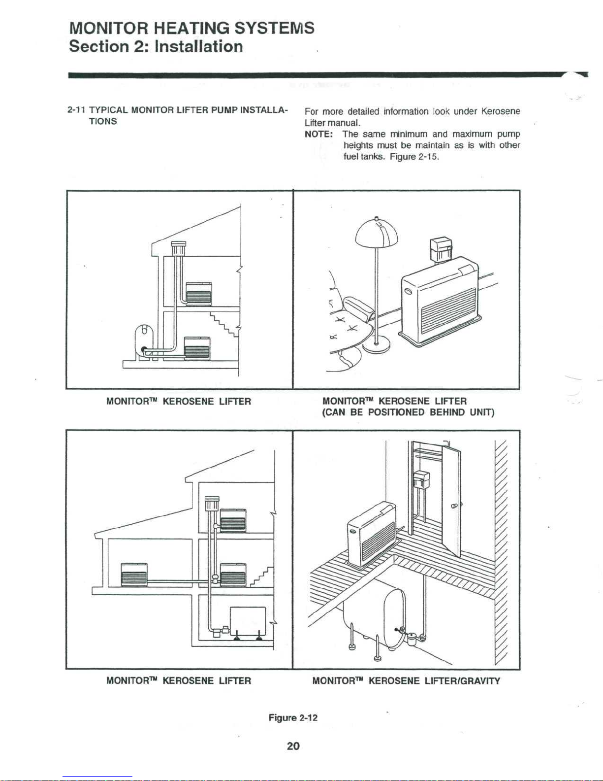
2-11 TYPICAL MONITOR LIFTER PUMP INSTALLA-
TIONS
For
more
detailed
information look under Kerosene
Lifter
manual.
NOTE:
The
same
minimum
and
maximum
pump
heights
must
be
maintain
as is
with other
fuel
tanks.
Figure
2-15.
MONITOR™
KEROSENE LIFTER
MONITOR™ KEROSENE LIFTER
(CAN
BE
POSITIONED BEHIND
UNIT)
MONITOR™ KEROSENE LIFTER
MONITOR™ KEROSENE LIFTER/GRAVITY
Figure
2-12
20
 Loading...