

Page 1

Installation Amplifiers 2G
Product Manual
Page 2
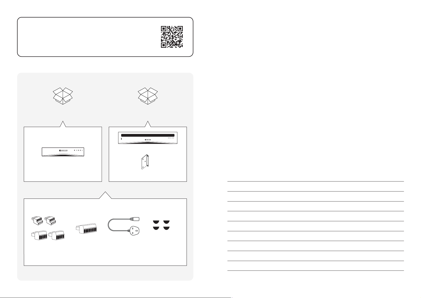
Register your Installation Amplier
Welcome to Installation Ampliers 2G
Register your amplier using the QR code
or visit monitoraudio.com/registration
IA60-4
IA125-4
Amplier Unit
IA750-2
IA750-4
Amplier Unit
x2
Rack Mount Brackets
Thank you for purchasing this Monitor Audio amplier.
This product has been designed to provide congurable, consistent and reliable high
performance audio power amplication for residential, commercial and entertainment
applications.
In this product manual, you’ll nd information about setting up and maintaining
this Installation Amplier.
If you need any further assistance, please contact our technical team
at monitoraudio.com/support
Contents
Connections overview 4
Connecting to network control 6
Configurations menus 8
Setup and signal routing 16
GPIO setup and connection 22
Input, output and GPIO cable connections 24
Installing 26
Input / Output
Connectors
Connector
Mains Cable Adhesive FeetGPIO Socket
Operation 28
Front LED colour matrix 29
Warranty 30
Specifications 31
2 3
Page 3
Connections overview
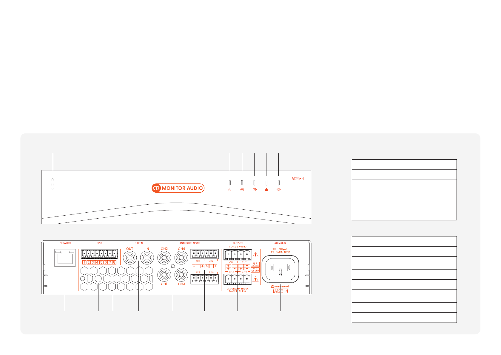
The Installation Amplier’s signal input and output connections are accomplished via
RCA Phono and Euroblock style connectors. A GPIO (General Purpose In/Out) Euroblock
connector enables some amplier functions to be controlled, and wireless or RJ45 socket
Ethernet network connection options are also provided.
Installation Ampliers have no mains power switch and are operational as soon as mains
power is connected via the IEC 60320 mains socket.
Prior to making any connections to the amplier we strongly recommend rst
connecting the amplier to the network and conguring the amplier for its intended
use, refer to page 6 for network connectivity and page 12 and 18 for output (Lo-Z or Hi-Z)
conguration.
21
3 4 5 6
Mains Power Connection
Installation Ampliers incorporate a power factor corrected power supply and can be
used with mains input voltage from 100V AC to 240V AC, 50/60Hz. Use the mains cable
supplied with the amplier and connect it to a switched mains supply.
Lo-Z and Hi-Z
Lo-Z refers to low impedance speaker connections (between 4-8Ohms). This is the
default Output mode for our Installation Ampliers. Hi-Z refers to high impedance
speakers (70/100 Volt line).
Front Panel
1 Power Button (IA750-4 only)
2 Status LED
3 Input LED
4 Output LED
5 Network LED
6 Wi-Fi LED
Back Panel
7 RJ45 Connection
8 Wi-Fi Attenna
9 GPIO Wall Contol Input (Selectable in Network
Contol)
10 Digital Audio Input/Output
11 Unbalanced RCA Inputs
12 Balanced Inputs, Mic Input on Channel 1 & 2
(sensitivity selectable in Network Control)
13 Speaker Outputs
7 98 10 11 12 13 14
4 5
14 IEC 60320 mains Input
Page 4

Connecting to network control
Before making input, output and GPIO connections, it is particularly important that the
output amplier format is congured appropriately for the speakers that are to be
connected. To do this, the amplier will need to be connected to the network. This can be
either wired or wireless.
Wireless Connection
A mobile, laptop or desktop device with WiFi functionality and a web browser is required.
Follow the steps below.
1. Connect the Installation Amplier to mains power using the supplied mains cable
and switch it on via the front panel Standby switch. Wait for the front panel WiFi
indicator to illuminate orange.
2. Use a mobile, laptop or desktop device to search for available WiFi networks.
Connect to, ‘MA [Amp Name] XXXX-XXXXX’ e.g. ‘MA IA750-4 2235-00018’ using the
password, ‘password’. The amplier serial number can be found on its rear panel.
3. Open a web browser and enter the following IP address: 192.168.4.1. The amplier
conguration web interface page will open in the browser app to enable amplier
conguration as required.
It is strongly recommended that the amplier WiFi password is changed following
initial wireless connection.
Continue to page 8 to learn about the conguration menus, setup and routing.
Wired Connection
A laptop or desktop device with Ethernet functionality, a web browser and a network
scanning app is required. Follow the steps below.
1. Connect the Installation Amplier Network Control socket directly to a laptop or
desktop device - or through a switch.
2. Connect the Installation Amplier to mains power using the supplied mains
cable and switch it on via the front panel Standby switch. Wait for the front panel
Network indicator to illuminate orange to indicate that the amplier has network
connectivity.
3. The default LAN IP address of the amplier is 192.168.64.100. Congure your laptop or
desktop device to a xed IP address in the same IP range, for example 192.168.64.10,
with Subnet mask 255.255.255.0 (or prex 24) and set Gateway to 192.168.64.1.
4. Open a web browser and enter the address http://192.168.64.100/ - The amplier
conguration web page interface will open to enable amplier conguration as
required.
Please refer to page 16 for speaker conguration before connecting your speakers.
The conguration menus are accessed via a web page interface and cover Input, Zone,
Output and General Settings functions. The conguration menus are fully described on
pages 8-23.
6 7
Page 5
Setup and signal routing
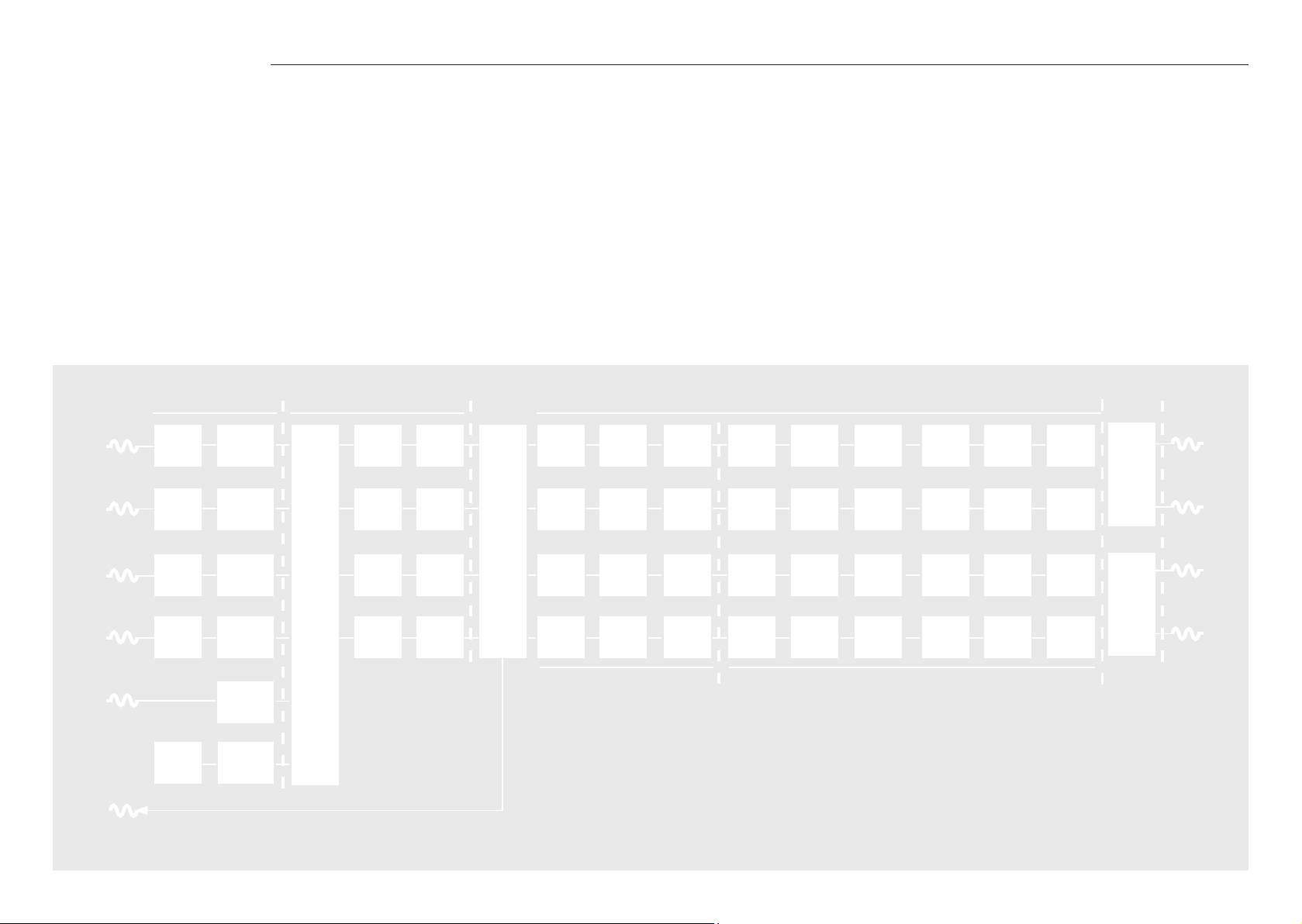
Thanks to their network based conguration features, our Installation Ampliers offer
considerable versatility in terms of sources, signal routing, installation zones and output
modes. Inputs can be freely assigned to installation zones, and those zones assigned
freely to the available amplier outputs in either Lo-Z or Hi-Z modes.
This versatility enables, for example, one amplier simultaneously to drive both Lo-Z and
Hi-Z speakers, or for different inputs to be routed to different output zones.
The following paragraphs describe and illustrate the recommended procedure for
conguring input, zone and output routing. A general signal ow schematic is also
illustrated in the diagram below.
Analog 1
Analog 2
Analog 3
Analog 4
SPDIF (stereo)
Input Setup
Input
Sensitivity
Input
Sensitivity
Input
Sensitivity
Input
Sensitivity
Pink
Noise
SPDIF Out (stereo)
Zones A (left) and B (right)
Input
Gain
Input
Gain
Input
Gain
Input
Gain
Input
Gain
Gain
Input
Selection
Zone Setup & Routing
Level
Adjustment
Level
Adjustment
Level
Adjustment
Level
Adjustment
Compressor
Compressor Gain Trim Delay EQ Crossover EQ FIR Driver
Output
Matrix
Zones A-D
Compressor Gain Trim Delay EQ Crossover EQ FIR Driver
Compressor Gain Trim Delay EQ Crossover EQ FIR Driver
Outputs 1-4
Gain Trim Delay EQ Crossover EQ FIR Driver
Alignment
Alignment
Alignment
Alignment
Zone Adjustment Parameters
Output Setup
Ploarity Limiter
Polarity Limiter
Polarity Limiter
Polarity Limiter
Speaker Preset Parameters
BTL
Amplier
2 x Lo-Z
1 x Hi-Z
BTL
Amplier
2 x Lo-z
1 x Hi-z
Output 1
Output 2
Output 3
Output 4
8 9
Page 6
Setup and signal routing
Dashboard
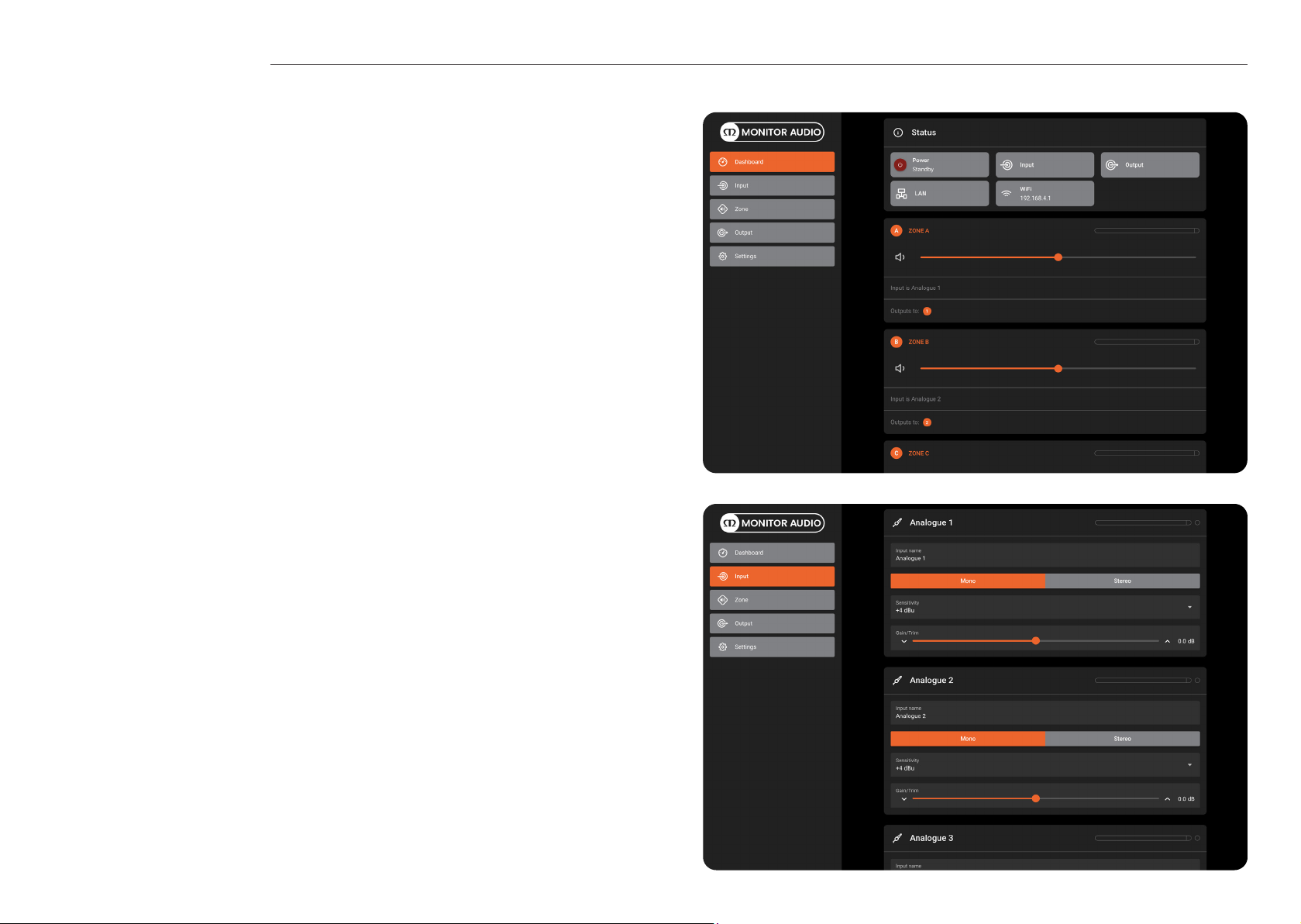
With the Installation Amplier succesfully connected to a network, searching the IP
address from a web browser displays the Installation Ampliers conguration Dashboard
screen, as shown in the image opposite.
From the Dashboard the power can be switched On/ Off and the volume for each zone
can be adjusted. If the name for the zone has been altered within the Zone tab the same
name will also be displayed here.
Input Setup
Open the conguration Dashboard and select the Input Tab. The Input Tab is shown
opposite.
• To edit default input names simply select and type in the Input Name eld.
• Dene a mono or stereo input by selecting the appropriate option. Dening a
stereo input will reduce the total number of discrete inputs available.
• Select an input sensitivity option from the drop-down menu: +14dB, +4dB, -10dB
and ‘microphone’ options are available. Generally, the +14dB or +4dB options are
appropriate for ‘professional audio’ source hardware with balanced outputs, while
the -10dB option is more appropriate for ‘consumer audio’ source hardware with
unbalanced outputs. The ‘microphone’ option provides the signicantly greater
sensitivity required for microphones.
Note: Only dynamic microphones are suitable for connection. Phantom power for
condenser microphones is not provided. If necessary, adjust the input gain using the
slider, up/down icons or enter the value manually. Gain adjustment is intended for ne
output level adjustment following initial use.
10 11
Page 7
Setup and signal routing
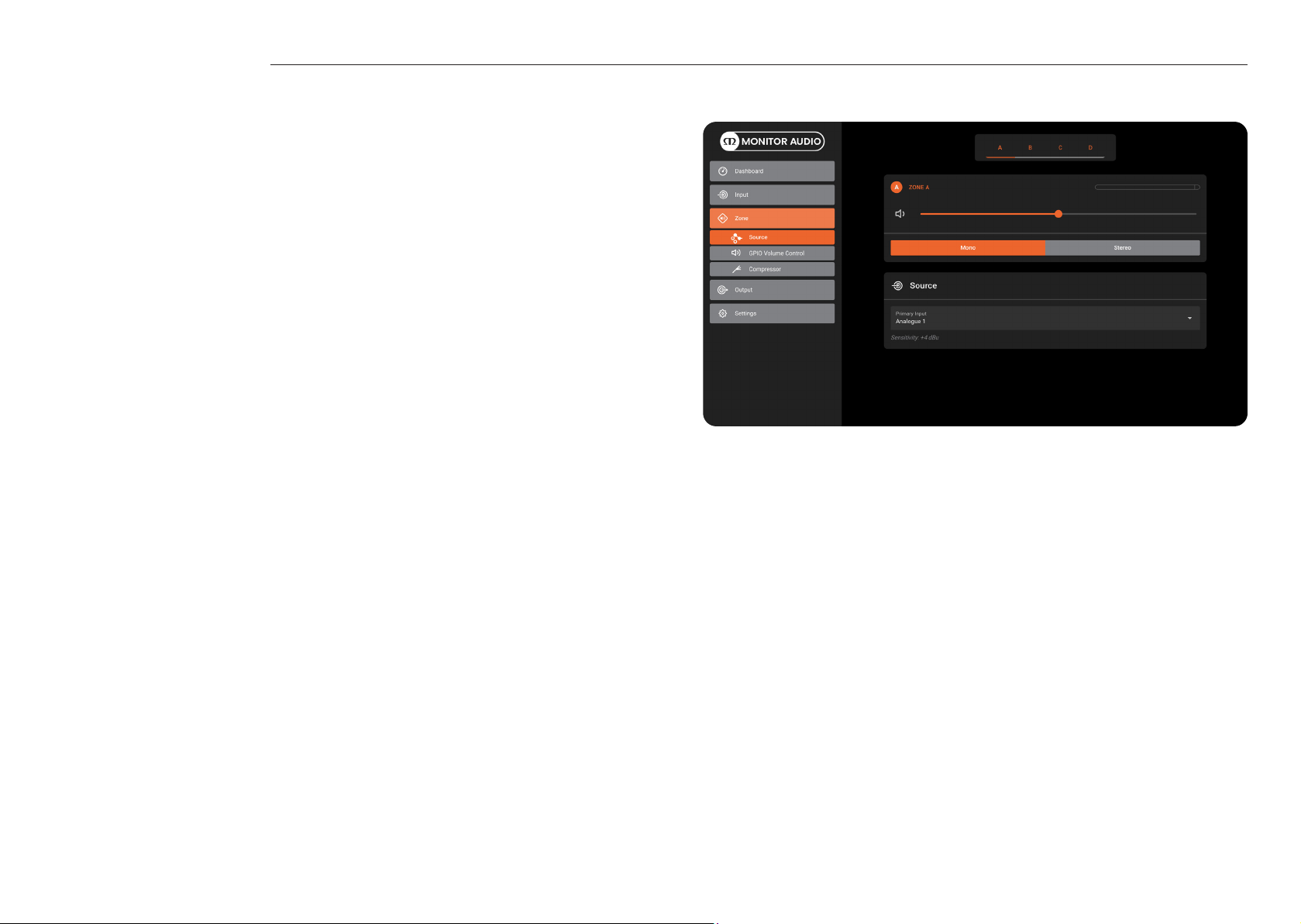
Zone Tab
The Zone Tab enables installation zones to be dened and named, and provides access to
further submenus. Zones might be bar or restaurant areas for example, or different rooms
in a home. For all Zone Tab menus, the installation zone under conguration is selected by
highlighting one of the zone identiers (A, B, C or D) at the top of the page.
Zone Setup & Routing
Open the conguration Dashboard and select the Zone Tab. The Zone Tab is shown
opposite.
• Select the zone to be congured from the top of the page. The number of zones
available will depend on the amplier model, input setup and output mode (Lo-Z or
Hi-Z). For example, a two output amplier will have two zones available if only mono
inputs congured, but have only one zone available if any stereo input is congured.
Similarly, a four output amplier with only mono inputs congured but one output
congured for Hi-Z mode will have only three zones available.
Note: When congured in Hi-Z mode Installation Ampliers operate in ‘bridged’ mode.
This is where the output of two channels is combined for an increase in power. This
means that the number of output channels available in Hi-Z mode is half that available
in Lo-Z mode. Outputs can also be bridged in Lo-Z mode if using the IA750-2 or IA750-4.
• Name the zone by typing in the Zone Name eld.
• Adjust the zone volume if required by using the slider.
• Dene a mono or stereo zone by selecting the appropriate option. Dening a stereo
zone will reduce the total number of further zones available.
• Specify an input for the zone by selecting from the drop-down menu. Selecting a
stereo input for a mono zone will automatically sum the stereo channels to mono.
(left -6dB + right -6dB)
• The GPIO Volume Control option enables external volume control to be applied to
individual installation zones. The GPIO conguration menu can be found under the
Settings Tab.
• The Compressor option enables default or custom signal compression to be applied
to individual installation zones.
Note: Compression can be useful to reduce the volume difference between loud and
quiet audio material. The lower the compression threshold is set, the more the difference
between loud and soft will be reduced. The overall zone volume may need to be increased
when compression is used. The default compression parameters are appropriate for most
installations.
12 13
Page 8
Setup and signal routing
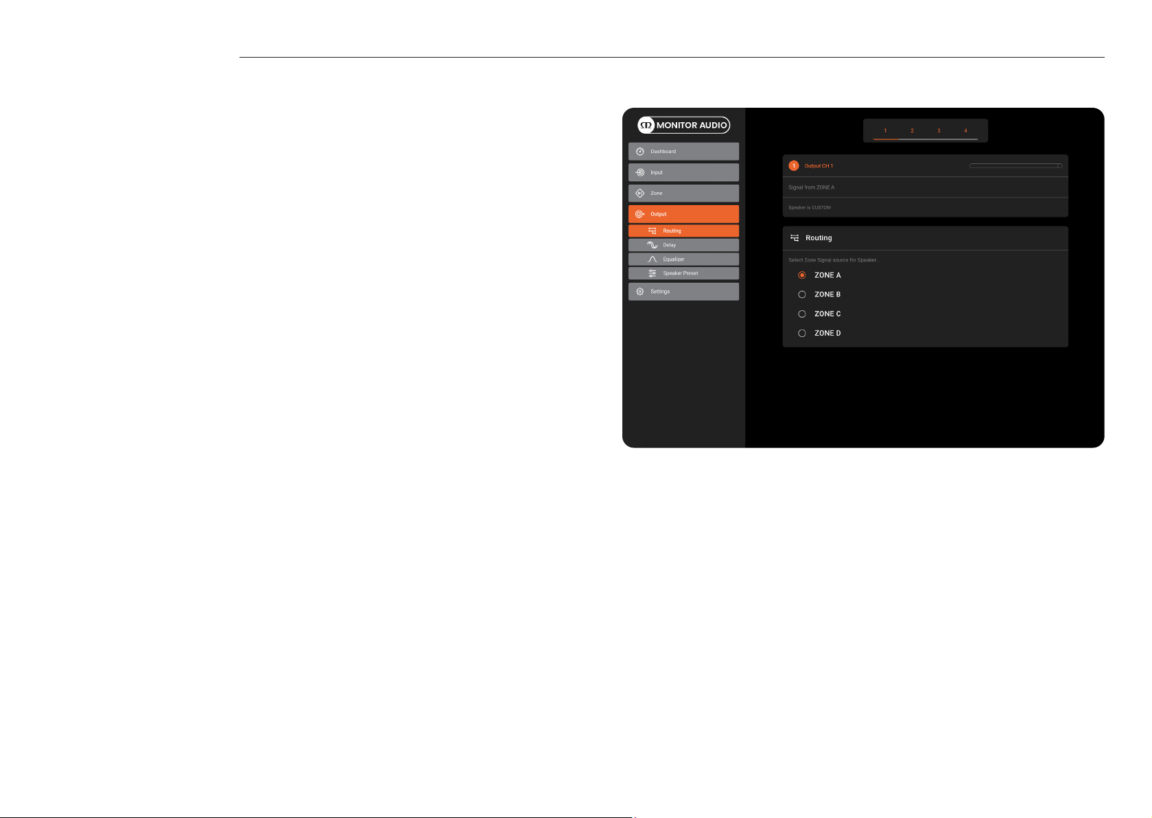
Output Tab
The Output tab enables amplier outputs to be named and provides access to further
sub-menus. For all Output Tab menus, the amplier output under conguration is
selected by highlighting one of the output identiers (1, 2, 3 or 4) at the top of the page.
Note: The number of individual outputs available for conguration will depend on the
Installation Amplier model and the input, zone and output mode conguration. For
example, the IA60-4 will have four outputs available if Lo-Z mode is selected and two
outputs if Hi-Z mode is selected. You can also mix by having two outputs in Lo-Z mode
and one output in Hi-Z mode.
14 15
Page 9
Setup and signal routing
Output Setup
Open the conguration Dashboard and select the Output Tab.
• Select the output to be congured.
• Specifying a Zone as stereo will automatically generate three output channel
options: left channel, right channel or summed mono. The summed mono signal
can potentially be used to drive a subwoofer (left -0dB + right -0dB).
• The Routing menu enables zones to be assigned to amplier outputs.
• The Delay menu enables audio delay to be applied to individual amplier outputs.
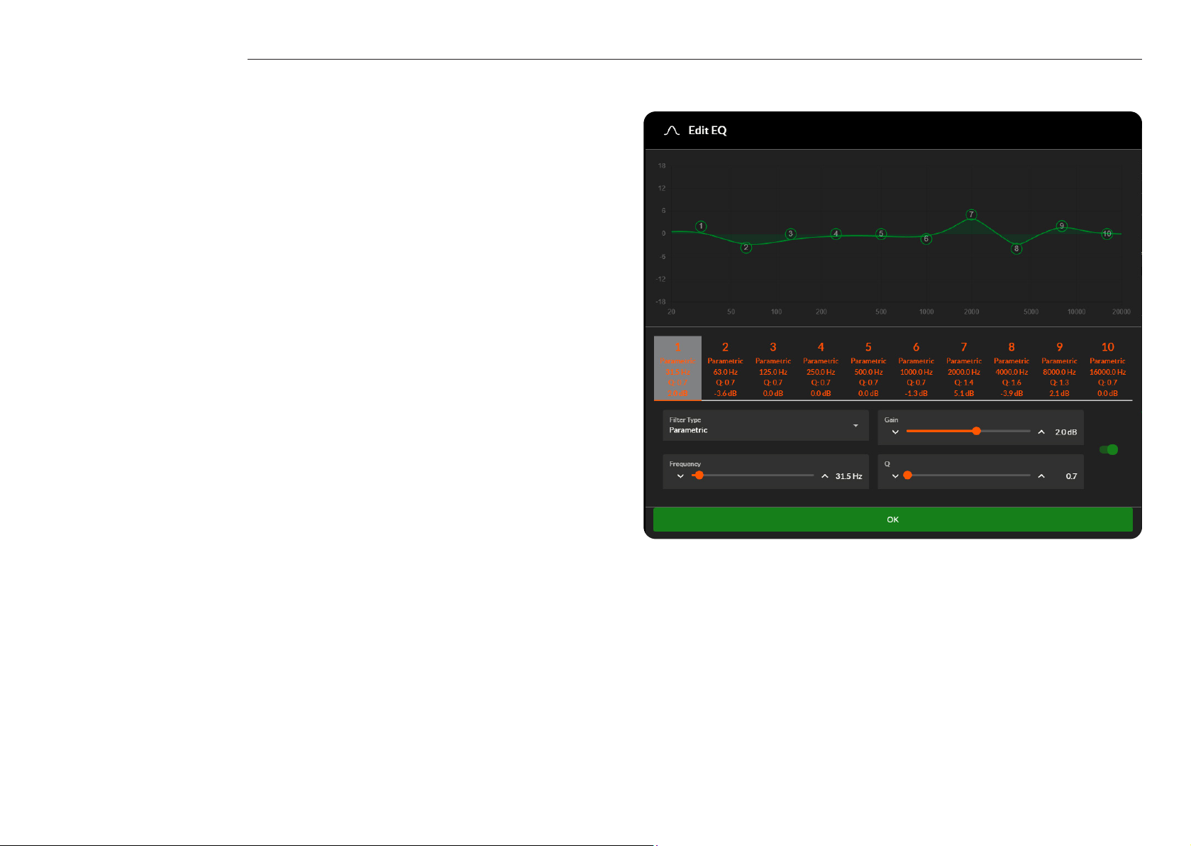
• The Equalizer menu enables parametric equalization to be applied to individual
amplier outputs. Equalizer settings congured for one amplier output can be
copied and applied to other outputs. The setting can be altered by pressing the Edit
function and using the sliders or by clicking on and dragging the different frequency
band numbers on the graph itself, as shown in the example opposite. To save any
changes press the OK button.
• Select the mode required for the output.
• The Speaker Preset menu allows you to Import or Export presets. For information on
creating speaker presets and adding them to your Speaker Library please refer to
page 21.
Selecting the Speaker Preset tab will also expand the listed options to show the
following sub-menus:
• The Crossover & Gain menu enables high or low-pass crossover lters and gain
adjustment to be applied to individual amplier outputs. Crossover lter settings
congured for one amplier output can be copied and applied to other outputs.
• The Speaker EQ menu enables parametric equalization to be applied to
individual amplier outputs following the application of crossover ltering.
Equalizer settings congured for one amplier output can be copied and
applied to other outputs.
• The Driver Alignment menu enables delay to be applied to individual amplier
outputs following the application of crossover ltering.
• The Polarity menu enables the polarity of individual amplier outputs to be
reversed.
• The Limiter menu enables signal limiting to be to be applied to individual
amplier output. There is are options for Clip, Peak and RMS Limiting.
Note: An output limiter can be used to restrict the peak volume level from speakers
connected to each output.
• The Output Mode menu enables individual amplier outputs to be switched off
or congured for Lo-Z or Hi-Z modes. In Hi-Z modes, a high-pass lter can also
be congured and applied to the output.
Note: Use of a high-pass lter with Hi-Z loudspeakers is useful to avoid the possibility
of distortion caused by low frequency line transformer saturation. Begin with the
default lter setting of 70Hz. If low frequency distortion is still audible, increase the
frequency setting one step at a time until the distortion is no longer audible.
16 17
Page 10
Setup and signal routing
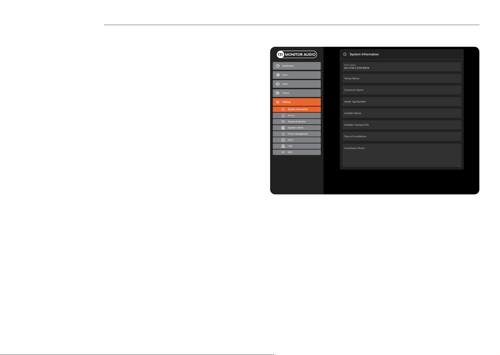
Settings Tab
The Settings Tab enables miscellaneous amplier settings to be congured and
installation data to be recorded. The Settings Tab provides access to further sub-menus.
• The System Information menu provides text elds for the recording of installation
data.
• The Device menu records amplier specic information such as the model number
and rmware version. A rmware update routine and identier ‘Find Me’ button can
also be found under the Device menu.
• The Backup & Restore menu enables amplier conguration data to be
downloaded to an external archive, and enables previously saved conguration
les to be uploaded and adopted by the currently connected amplier. The
connected amplier can also be reset to factory settings from here.
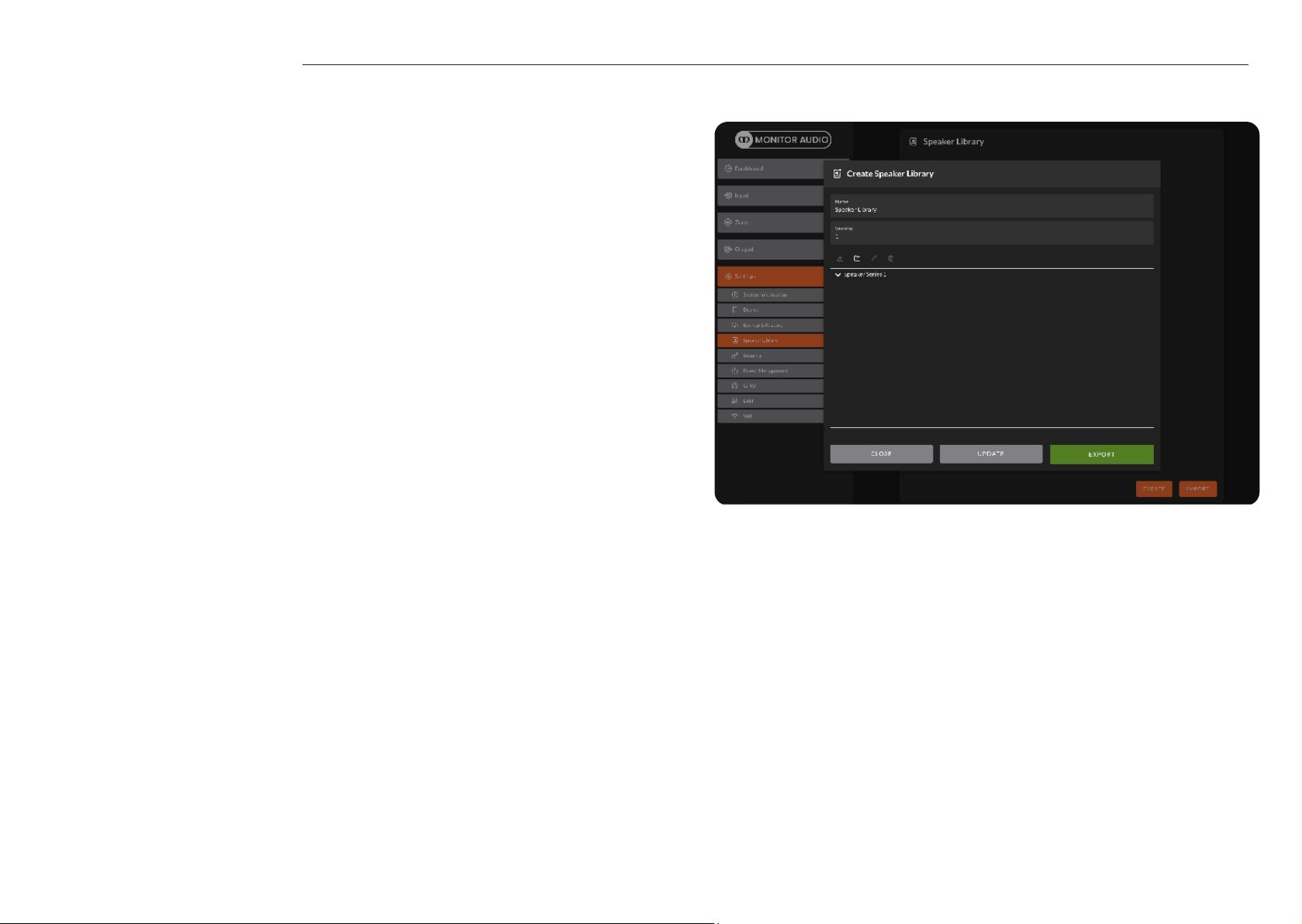
• The Speaker Library menu allows you to create a Library of presets and order them
into folders. Refer to page 20 for instructions on creating presets and adding them
to your library.
• The Power Management menu enables various automatic switch-on options to
be engaged. The Power Management menu also offers timed Standby and Mute
functions.
• The GPIO menu enables conguration of the multi-purpose GPIO interface pins,
refer to page 22.
• The LAN menu enables conguration and reset of the wired network options and
parameters.
• The WiFi menu enables conguration and reset of the wireless network options and
parameters.
18 19
Page 11
Presets and Speaker Library
Speaker Presets
Speaker Presets can be made from the parametres and settings within the Speaker
Preset sub-menus in the Output tab.
Once you have made your adjustments e.g. Crossover & Gain, Speaker EQ, etc you can
export it to a preset to use later.
When exporting presets you can select which settings you wish to export from a checklist
and also if you want them to be protected. This will prevent others from making further
changes to your preset.
A selection of Presets for Monitor Audio loudspeaker combinations and individual
loudspeakers is available from our website: monitoraudio.com
To import presets select Import and then locate the preset le (*.zcp). You can also
import presets that have been added to your Speaker Library, which can be generated in
the Settings tab. Press ‘Customize Preset’ to modify and enable access to settings.
Speaker Library
You can add your speaker presets to a Speaker Library, which can then be exported and
imported between Installation Ampliers. To make a new Speaker Library go to the tab in
Settings and select Create, you will then be asked to name the library and set a version
number.
Select Speaker Series 1. Using the icons to the right of the window you can Import Speaker
Preset(s), Add Series, Edit Series or Delete.
Using the Import Speaker Preset function you can build your library to include all of your
speaker presets that you use. Once you have nished press Update to save the changes.
20 21
Page 12
GPIO setup and connection
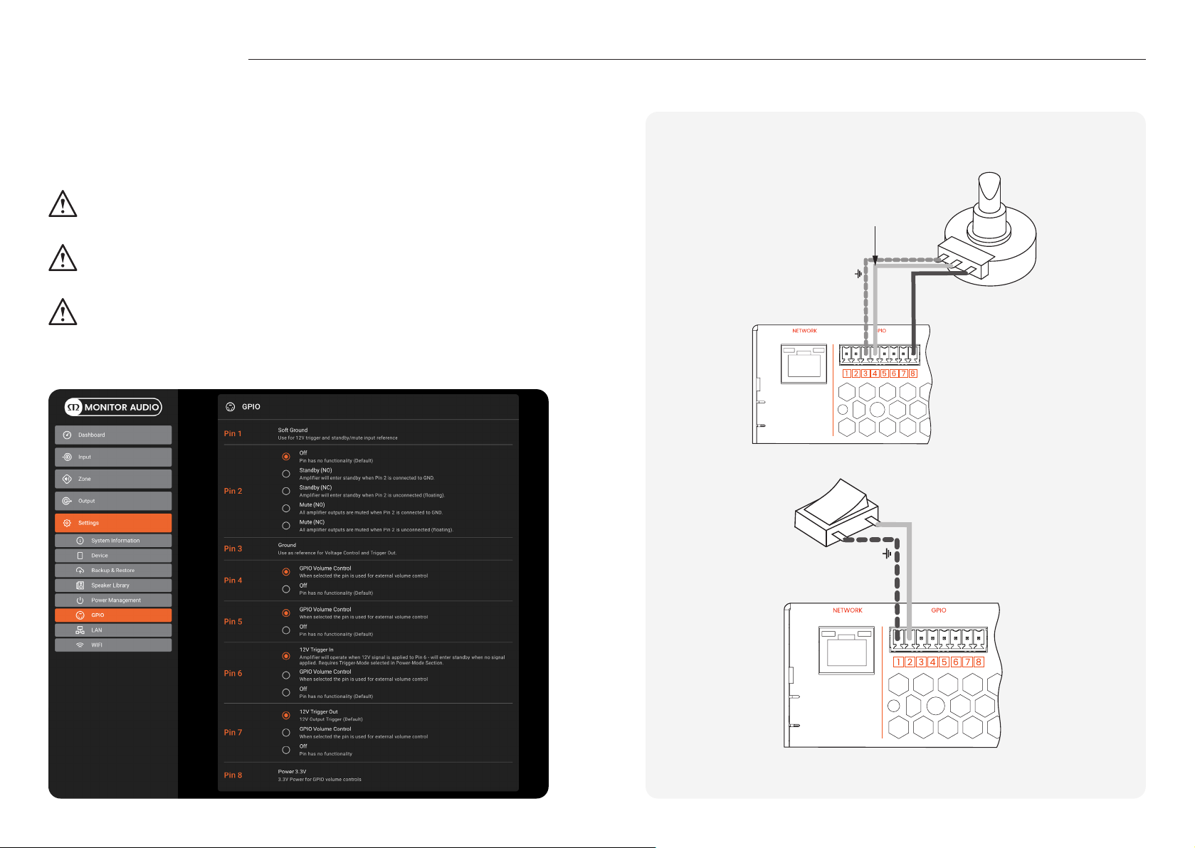
Our Installation Ampliers provide a GPIO socket that enables remote control of volume,
standby, mute and trigger functions. The GPIO connector pin functions are described
in the GPIO Settings menu shown below. The connection of GPIO based remote volume
control and standby/mute are illustrated on the right.
Potentiometer
(>10kΩ)
Note: The GPIO connector must NOT be used for any unintended purpose.
Amplier damage may result from incorrect use of GPIO.
Note: Shielded cable must be used when connecting standby switches and
potentiometers via GPIO.
Note: GPIO Pin 8 has an output impedance of 1kΩ. Connected devices must be
able to sink 3.3mA.
Connect Wiper to
Pin 4, 5, 6 or 7
Ground
+3V3
Ground
Standby/Mute
22 23
Page 13
Input, output and GPIO cable connections
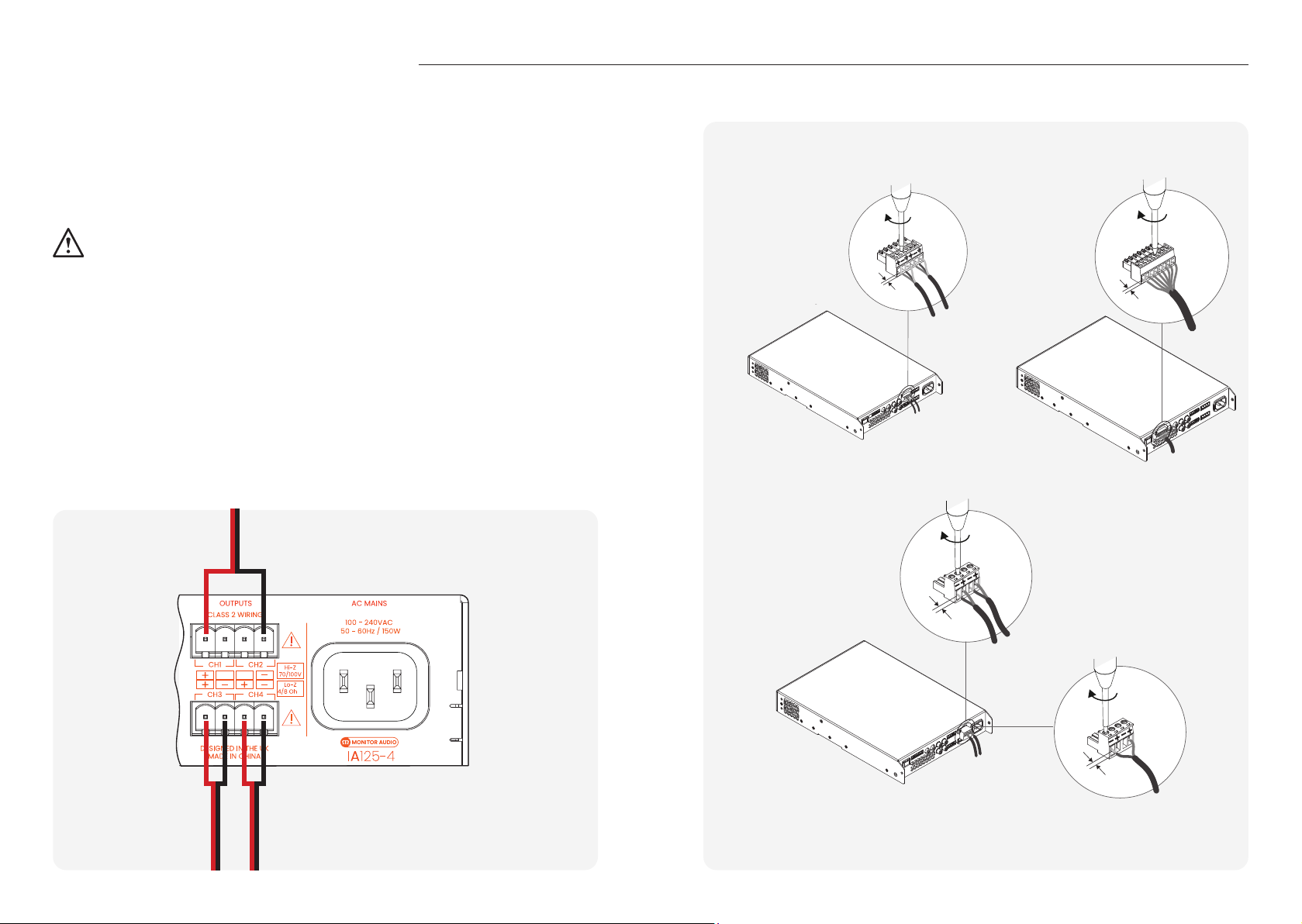
Cable connections to the Input and Output block connectors should be made with bare
wire with a maximum thickness of 14 AWG for the GPIO connector and 12 AWG for the
speaker connector. Insert the cable into the relevant opening on the Phoenix connector
and secure it in place using a at headed screwdriver. Please refer to the diagrams
below for wiring your Output, Input and GIO cable connections.
Do not touch the output terminals while the amplier is switched on. All
connections should be made with the amplier switched off and the mains
cable removed.
Balanced Analogue Input GPIO Cable Connection(s)
If using the Lo-Z channel Output Mode connections will be made to the positive and
negative connections as shown below. If using the channel Hi-Z or Bridged Output
Modes both channels are joined to offer increased power and connections are made
to outermost positive and negative connections, as shown below.
Hi-Z Mode / Bridged Mode
Output Cable Connection(s)
5 mm
5 mm
Ch 2/4
Lo-Z Mode
Ch 1/3
5 mm
Hi-Z Mode /
Bridged Mode
5 mm
Lo-Z Mode
24 25
Page 14
Installing
Mounting
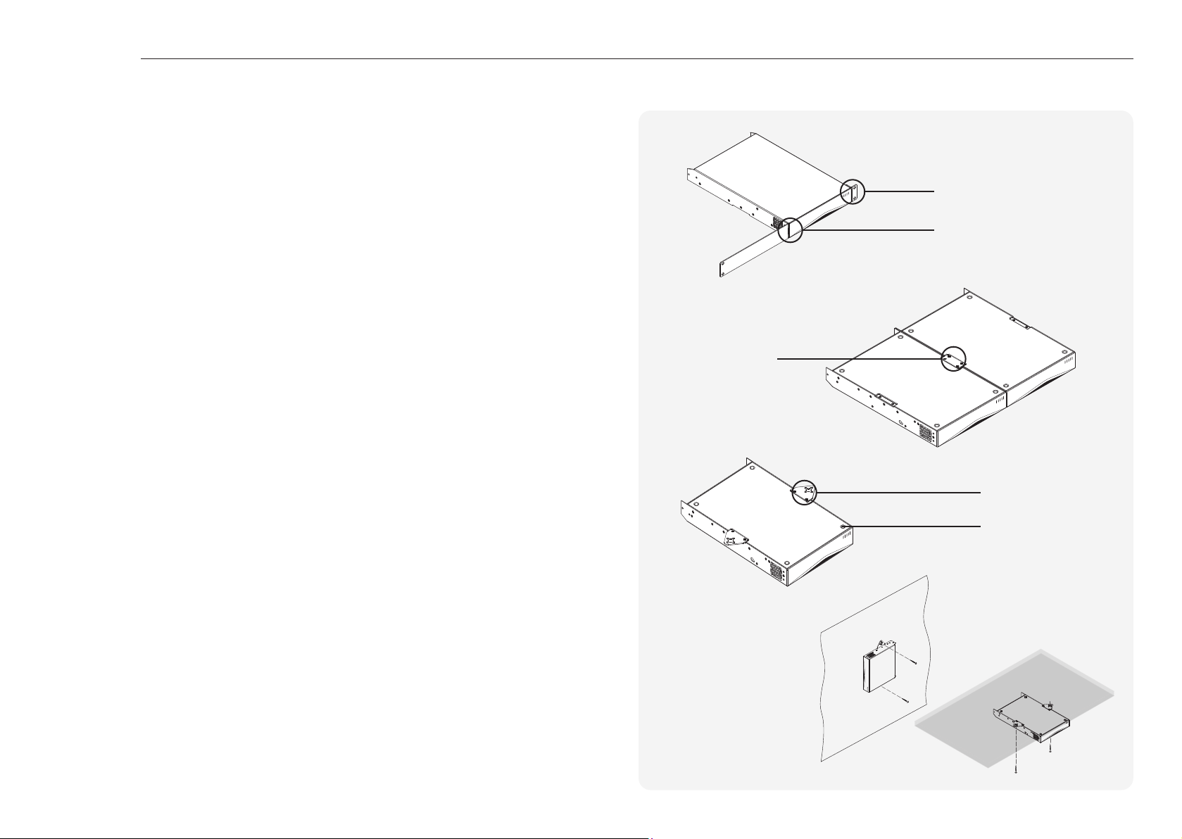
Note: The rack mounting and desk/wall mounting components described and illustrated
on the right are not supplied with half rack models, but are available to purchase as
accessories. Contact your local MA dealer for more information.
Half rack Installation Amplier models can be congured for rack installation using one
standard rack ‘ear’ and one half-rack extension piece as illustrated in the right image.
Full rack models will use two standard rack ‘ear’ brackets on both sides. Multiple half
rack Installation Ampliers can also be secured side by side using accessory connecting
plates, as shown in the image below.
If not installed in an equipment rack, Installation Ampliers can be placed freestanding on a at surface. Adhesive rubber feet are supplied for this purpose.
Installation Ampliers can also be attached to the underside of desks or wall mounted
using connecting plate hardware. The adhesive rubber feet should also be used in
these circumstances to minimise the possibility of vibration between the amplier and
mounting surface. Wall and desk mounting is illustrated opposite.
Providing sufcient airow
The installation and equipment rack should be congured to provide appropriate
ventilation airow space around the sides and rear of the amplier, please refer to the
next section below. Ventilation airow space of at least 25 mm (1”) should be maintained
along at least one side of the amplier at all times. Ventilation apertures are also located
on the rear panel of the amplier and must not be obstructed. It is important to retain at
least 80 mm (3”) free space for airow behind the amplier rear panel.
Connection Plate
with four M3 x 6mm
countersunk bolts
Rack Ears connected
with two M4 x 8mm countersunk bolts
Half-rack Extension +
2 x M4 x 8mm countersunk bolts
Mounting Plate tted with two
M3 x 6mm countersunk bolts
Four adhesive
foot positions
26 27
Page 15

Operation Front LED colour matrix
Once all connections have been made and conguration options selected, the
Installation Amplier(s) are ready for use. If an input signal above -60dB is present on
any input, the front panel Input and Standby indicators will illuminate orange to indicate
normal amplier operation. Audio will be heard from any connected speakers.
Note: Installation Ampliers will not switch on from Standby Mode unless an analogue
input signal is present or a network or external standby switch is operated.
Amplier outputs will mute if no input signal is present for 5 minutes, and the amplier
will switch automatically to Standby Mode if no signal is present on any input for more
than 15 minutes. Alternative standby and mute delay times can selected via the Settings
Menu. Amplier cooling fan speed is temperature controlled. The fan will switch off when
the amplier enters standby mode.
The front panel LED indicators will illuminate to indicate the following operational states:
Off Mains Power Disconnected
Orange Amplier Operational
Status LED
Input LED
Output LED
Network LED
Wi-Fi LED
Pulse Orange Standby Mode
Pulse Orange GPIO Triggered Standby Mode
Off No Input Signal Detected
Orange Signal Detected
White Input Overloaded / Clipping
Off No Output Signal Detected
Orange Signal Detected
White Signal Limiting / Clipping
White Channel is in Overload / Protection Mode
Off No Network Detected
Orange Network Detected
Off Wi-Fi Disabled
Orange Wi-Fi Enabled
28 29
Page 16
Warranty
Specications
In the unlikely event that there is a defect with this product, it is covered by
the Monitor Audio manufacturer’s warranty, provided that the product was
supplied by an authorised Monitor Audio retailer.
For the period of cover please refer to the product page on our website
at monitoraudio.com
Register your Installation Amplier
Register your amplier using the QR code
or visit monitoraudio.com/registration
Model IA60-4 IA125-4
Channels 4 4
Output Power @ 4 Ohms/8 Ohms 4 x 60W SE* 4 x 125W SE
Output Power @ 70/100V 2 x 125W BTL** 2 x 250 BTL
Poweshare (up to) 1 x 250W 2 x 250W
Power Consumption 75W 150W
Thermal Output 256 BTU 512 BTU
Polarity (Default) Non-inverting
3/4
11/16
Dimensions 44 x 220 x 325mm (1
Output Voltage 70Vp / 140Vpp (SE unloaded), 140Vp / 280 Vpp (BTL unloaded)
Signal to noise-ratio >106dB (A-weighted, 20Hz - 20kHz, 8 Ohm load)
THD+N (typical) <0.05% (20Hz - 20kHz, 8Ohm load, 3dB below rated power)
Frequency Response +0/-0.25dB 20Hz - 20kHz (8 Ohm load, 3dB below rated power)
Protection Circuits Short circuit, DC, Undervoltage, Temperature and Overload protection
Power Supply Switch mode power supply with Power Factor Correction (PFC) and stand-
Operating Voltage/Frequency Universal Mains, 100V-240V, 50Hz-60Hz
Standby Consumption <0.5W
Accessories Rack Mount Kit, Wall/desktop mount kit (sold seperatley)
Power Ratings 1% THD @ 120Vac and 230Vac
Cabinet Finish Black Anodised
by converter
x 8
x 11
5/8
”)
* SE - Single Ended
** BTL - Bridge Tied Load
*** BTU - British Thermal Unit
30 31
Page 17

Specications
Model IA750-2 IA750-4
Channels 2 4
Output power @2 Ohms 2 x 750W SE 4 x 750W SE
Output Power @ 4 Ohms 2 x 750W SE, 1 x 1500W BTL 4 x 750W SE, 2 x 1500W BTL
Output Power @ 8 Ohms 2 x 400W SE, 1 x 1500W BTL 2 x 400W SE, 2 x 1500W BTL
Output Power @ 70V 1 x 1200W BTL 2 x 1200W BTL
Output Power @ 100V 1 x 1500W BTL 2 x 1500W BTL
Maximum totally output power,
all channels driven
Power Consumption 350W 700W
Thermal Output 1200 BTU 2400 BTU
Polarity (Default) Non-inverting
Dimensions 88 x 440 x 329mm (3
Output Voltage 80Vp / 160Vpp (SE unloaded), 160Vp / 320Vpp (BTL unloaded)
Signal to noise-ratio >108dB (A-weighted, 20Hz – 20kHz, 8 Ohm load)
THD+N (typical) <0.05% (20Hz – 20kHz, 8 Ohm load, 3dB below rated power)
Frequency Response +0/-0.5dB 20Hz – 20kHz (8 Ohm load, 3dB below rated power)
Protection Circuits Short circuit, DC, Undervoltage, Temperature and Overload protection
Power Supply Switch mode power supply with Power Factor Correction (PFC) and stand-
Operating
Voltage/Frequency
Standby Consumption <0.5W
Accessories Rack mount kit (pre-installed)
Power Ratings 1% THD @ 120Vac and 230Vac
Cabinet Finish Black Anodised
1500W 3000W
6/16
5/16
15/16
x 17
x 12
”)
by converter
Universal Mains, 100V-240V, 50Hz-60Hz
32 33
Page 18

Monitor Audio Ltd.
24 Brook Road
Rayleigh, Essex
SS6 7XJ
England
Tel: +44 (0)1268 740580
Email: [email protected]
monitoraudio.com
©Monitor Audio Ltd. | V1-2022 - Installation Amplier 2G Manual
 Loading...