

Page 1

Owners Manual
Installation Amplifiers
Page 2

Page 3

monitoraudio.com 1
English 2
Français 12
Italiano 24
Deutsch 36
Español 48
Português 60
Nederlands 72
中文 84
РУССКИЙ 96
БЕЛАРУСКАЯ 108
ҚАЗАҚША 130
日本語 142
154
ةيبرعلا
Polski 166
Page 4

Installation Amplifiers2
Contents
Introduction 2
Connections Overview 3
IA150-2 3
IA60-12 3
IA200-2C 4
IA150-8C 4
IA800-2C 5
Connection Descriptions 5
LED Indicators 6
Bridging Channels 6
Feet 7
Rack Mounting your Amplifier 7
Connecting to a Network 7
Configuring your 'Connect' Amplifier Using
the Web Portal 8
Basic Settings 8
Input/ Output Settings 9
DSP Configuration 10
Infrared Remote Codes 12
Troub les ho oti ng 12
Guarantee 12
Owner Information 12
Specifications 13
Introduction
Introducing the Monitor Audio Installation Amplifiers, built to do more and use less space, featuring cuttingedge technology for the best sound performance in any installation project. The multi-channel amplifiers
can be used in a wide range of applications in residential and commercial properties with power up to 2000
watts. Audio channels can be grouped or bridged for flexible installations, configurable up to 12 channels.
We have selected the world renowned Hypex amplifiers to guarantee reliability and the great sound quality
you’d expect from Monitor Audio, reduced into slim 1U and 2U high cases that universally fit into most
racks whilst delivering 93% energy efficiency.
All amplifiers feature full connectivity with simple wired voltage trigger or signal sense.
'Connect' amplifiers include more complex DSP and IP control, offering wider flexibility and integration.
Page 5
monitoraudio.com 3
Connections Overview
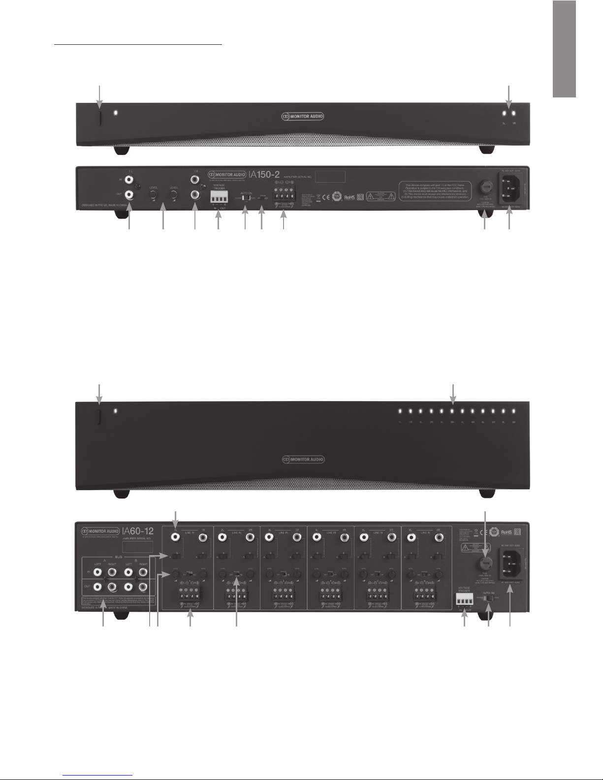
IA150-2
IA60-12
FRONT PANEL
1. Power Button
2. Channel Indicator LED
REAR PANEL
3. Left Channel RCA Input/
Output
4. Volume Level Control
5. Right Channel RCA Input/
Output
6. Trig ger In pu t/O ut put
7. Auto On Switch
8. Bridge On/Off Switch
9. Speaker Block Connector
10. AC Fuse Holder
11. Power Cord Connection
FRONT PANEL
1. Power Button
2. Channel Indicator LED
REAR PANEL
3. Channel RCA Inputs
4. AC Fuse Holder
5. Bus RCA Inputs/Outputs
6. Channel Input Switch
7. Volume Level Control
8. Speaker Block Connector
9. Bridge On/Off Switch
10. Trig ger In pu t/O ut put
11. Auto On Switch
12. Power Cord Connection
ENGLISH
1 2
3
5 6 7 8 109 11 12
4
1 2
3 4 5 6 7 8 9 10 11
Page 6

IA200-2C
IA150-8C
FRONT PANEL
1. Power Button
2. Channel Indicator LED
3. Output Volume Control
REAR PANEL
4. IR Control Input and Output
5. IR Status LED
6. Channel RCA Inputs/
Outputs
7. Voltage Trigger Input/Output
8. Ethernet (RJ-45)
Connection
9. Speaker Block Connector
10. AC Fuse Holder
11. Power Cord Connection
FRONT PANEL
1. Power Button
2. Channel Indicator LED
3. Output Volume Control
REAR PANEL
4. IR Control Input/Output
5. IR Status LED
6. Ethernet (RJ-45) Connection
7. Voltage Trigger Input/Output
8. Speaker Block Connector
9. Channel RCA Inputs/
Outputs
10. AC Fuse Holder
11. Power Cord Connection
6
54
1 2
3
7 8 9 10 11
6
54
1
3
2
7 8 9 10 11
Installation Amplifiers4
Page 7

IA800-2C
Connection Descriptions
FRONT PANEL
1. Power Button
2. Channel Indicator LED
3. Output Volume Control
REAR PANEL
4. Speaker Block Connector
5. Channel RCA Inputs/
Outputs
6. Voltage Trigger Input/Output
7. IR Control Input/Output
8. IR Status LED
9. Ethernet (RJ-45) Connection
10. AC Fuse Holder
11. Power Cord Connection
ENGLISH
1 2
4 6 7
8 9
5 11
10
3
AC Fuse Holder
This compartment houses the amplifier's internal
fuse, should the fuse ever require changing the
compartment can be opened by inserting a flat
headed object such as a screwdriver and turning
anti-clockwise. Refer to the information printed on
the product below the fuse holder for the correct
fuse specification.
Power Button
This is the main power switch for the amplifier.
Please ensure the amplifier is turned off if not used
for long periods of time.
Output Volume Control
'Connect' models only.
Use a small flat headed screwdriver to increase or
decrease the volume of the output. This is linked
to the "Output Volume" on the web portal. Refer to
page 10. Turn anticlockwise if clipping/ distorting
(as indicated by the channel LED on the front), or
clockwise for more volume.
Channel RCA Inputs
Stereo left and right RCA connectors for connecting
audio sources. Models with an increased number
of channels such as the IA60-12 will feature more
inputs for the number of output channels available.
Channel RCA Outputs
Stereo left and right RCA connectors for connecting
to external playback devices such as active
subwoofers or to additional amplifiers.
Volume Level Control
IA150-2 and IA60-12 only.
Used to increase or decrease the output volume.
Reduce if the speakers are clipping, increase if the
output volume is too quiet.
Ethernet (RJ-45) Connection
'Connect' models only.
Used to make connection to a wired network. Once
connected amplifier will become visible on the
network to other devices. Refer to page 8 on how
to setup your 'Connect' amplifier.
Voltage Trigger Input and Output
Trigger connection can be made to the input/
output of another device. When using the input the
amplifier will switch on and off with the connected
device. A device connected to the output of the
amplifier will switch on and off with the amplifier.
monitoraudio.com 5
Page 8

Auto On Switch
IA150-2 and IA60-12 only.
There are three settings; Voltage, Audio and Off. In
the Voltage setting the Trigger method will be used
to wake up the amplifier from standby. In the Audio
setting the amplifier will wake from standby when
an audio signal is present. It will return to standby
when no signal is present for 15 minutes. In the Off
setting the amplifier can only be switched On and
Off manually.
Bridge Switch
IA150-2 and IA60-12 only.
Switch On or Off Bridge mode, with this activated
two outputs are combined to produce more output
power.
Bus RCA Inputs
IA60-12 only.
Stereo left and right RCA inputs for connecting
audio sources. Unlike the Channel RCA connectors
the Bus RCA inputs can be routed to multiple
output channels.
Bus RCA Outputs
IA60-12 only.
Stereo left and right RCA outputs. This can be used
if you wish to daisy chain the Bus Input signal to
external devices/ additional amplifiers.
Bus Switch
IA60-12 only.
Select the audio source input for the channel on the
amplifier.
Speaker Block Connector
Accepts up to 12 gauge cable for connecting
speakers, please refer to the next column of this
page.
IR Input
Connect an infrared receiver to this input to control
the amplifier using programmable remotes. Please
refer to page 12 for discreet commands/ Hex
codes.
IR Output
For use with an infrared repeater or linking to the
IR input on other amplifiers, this will allow multiple
devices to receive the same command from a single
remote command. For example a single power On/
Off command could be used for an entire rack of
installation amplifiers rather than individually.
LED Indicators
Power LED (Orange LED):
LED Dim Orange - standby mode
LED Bright Orange - power on
Flashing Bright Orange LED - identification mode or
updating
Channel LED (Orange/ White Dual LED):
LED Off - no signal present
Orange LED - signal present
White LED - channel is clipping or the amp has
gone into protection mode
Flashing White LED - thermal protection
If experiencing clipping or thermal protective LED
patterns decrease the volume, if the issue remains
please refer to the troubleshooting section on page 12.
Connecting your Speakers
All amplifiers feature speaker block connectors for a
secure and safe connection to your speakers, these
blocks are removable for easy access. Using a flat
headed screwdriver loosen the screw heads at the
top of speaker block and insert speaker cable up to
12 gauge into the front openings. Tighten the screw
heads to clamp the speaker cable in place.
Bridging Channels
WARNING: The minimum speaker
impedance for bridged operation is 8
Ohms. Do not connect any speakers in
bridged mode that are less than 8 Ohms
nominal impedance.
1. Set the zone’s BRIDGE switch to the ON position,
refer to the Connections Overview section.
2. Connect the speaker's “+” lead to the left
channel connector marked “+” and the speaker’s
“–” lead to the right channel connector marked
“+”. The "-" outputs are not used.
Installation Amplifiers6
Page 9

Feet
Every amplifier model is supplied with four rubber
feet for when used out of a rack. To attach the feet
simply screw them into the four threaded inserts on
the base of the amplifier.
Rack Mounting your Amplifier
Every amplifier model is supplied with rack bracket
fixings for mounting the amplifier in standard 19"
racks. To fit the brackets, simply remove the 4
screws on each side of the amplifier towards the
front. Place the brackets over the holes that have
been revealed and use the same screws to attach
the brackets.
Powering the Amplifier
All models are supplied with an IEC mains cable.
Each time the amplifier’s mains cable is initially
plugged in and the power switch is turned ON, all
channel outputs are disconnected for approximately
12 seconds and all Channel Indicator LEDs will
illuminate briefly while the amp boots up.
NOTE: Do not switch on the power at
the wall outlet until all system
connections have been made.
Connecting to a Network
NOTE: This section applies to
'Connect' models only.
1. Connect the amplifier to a network switch
using an ethernet cable. Make sure the
computer and amplifier are on the same
network.
2. Turn o n t he am pl ifie r.
3. The amplifier will be issued an IP address by
the DHCP Server.
4. Run an IP address finding application such as
'Advanced IP Scanner' (Windows only), which
is available for free download from here:
https:/ / www.advanced-ip-scanner.com
5. Launch 'Advanced IP Scanner' (or a preferred
application) and enter your networks IP range
(managed by your router) into the search bar
at the top. Click on Scan to search.
6. The IP address of the amplifier in the list will
have a drop down option that when double
clicked will take you to the amplifier's web
setup .
Alternatively, all network IP addresses will be
accessible from your Router configuration
page.
Once the amplifier's IP address is known it can
be entered into a web browser of your choice
to open access the web portal.
monitoraudio.com 7
ENGLISH
Page 10

Configuring your 'Connect'
Amplifier Using the Web Portal
Basic Settings
Here the most basic general amplifier settings can
be edited and saved. The following section will take
you through each of the functions on this tab.
NOTE: Some changes made in the
web portal will not be visible until the
page is manually refreshed or you
navigate to one of the other pages.
Information
Here you can add a name for the amplifier and
enter the installation details for future reference. The
amplifier model, firmware version and serial number
are displayed here, these are non-editable.
Network
IP Address – Shows the current IP address used
when DHCP is ON. When DHCP is set to OFF this
allows you to enter a desired static IP address.
IP Subnet Mask – Shows current IP Subnet Mask
used when DHCP is on. When DHCP is set to OFF
this allows you to enter a desired IP Subnet Mask.
NOTE: If changing the IP address or
the Subnet Mask, the new IP address
will need to be entered into the web
browser to see the amplifier's web portal again.
Identification Mode
When this option is switched ON the front power
LED will start flashing. This is useful for identifying
which amplifier is being configured when using
multiple amplifiers.
Print
Press this to open a printable page with all current
amplifier settings.
Power ON
Here you can select from a selection of Power On
Methods (described below) for what best suits your
installation. Also a powering On delay can be set
from 0-20 seconds, this is useful when you want
a series of amplifiers to switch On in a specific
sequence.
Power Button – Turn off signal sense and voltage
trigger detection. The power state is controlled by
the power button on the unit only.
Audio – This mode uses signal sense to turn the
amplifier on. Additionally, communication over the
network is still possible. In this mode the amplifier
will consume up to 2W in standby.
Voltage Trigger – Turn amplifier on with 12v
Voltage Trigger.
Audio Green – This mode uses signal sense to
turn the amplifier on. If no signal is received for
approximately 15 minutes the amplifier will enter
standby. Network communication is turned off
when in standby, to communicate with the amplifier
it needs to be woken from standby. In this mode
the amplifier will consume up to 0.5W in standby.
Voltage Green – This mode uses the voltage
trigger to turn the amplifier on and off. Network
communication is turned off when in standby, to
communicate with the amplifier it needs to be
woken from standby. NOTE: In this mode the
amplifier will consume up to 0.5W in standby.
Installation Amplifiers8
Page 11

ENGLISH
Save & Restore
Here all settings can be saved to a file, which can
then be used to restore the settings from if required.
Load Global Preset
Active Global Preset – Show current active Global
Preset (this displays the name of the currently active
global preset, this is not a text input box) – with
reset button to reset current active preset to default
settings.
Select Global Preset – Selects which preset you
wish to edit and implement from drop down menu.
The load button next to the drop down menu will
activate the selected preset and restart the amplifier
after confirmation from the pop-up prompt. The
active global preset will change when the web page
has been refreshed.
Edit Preset name – Text field to edit name of the
preset currently selected from drop down menu.
Import/ Export Global Preset
All Presets – Import/ Export all Global Presets to/
from a file.
Single Preset – Import/ Export a single global
preset from menu to/ from a file.
Duplicate Global Preset
Copy Global Preset 'X' to Global Preset 'Y'. Both of
which are selectable from the drop down menus.
Reset
Factory Reset – Reset button will reset all settings and
all presets (global & DSP) to original factory settings.
When pressed the power LED on the amplifier will
flash, followed by restarting.
Update
Firmware Update - This button will install firmware
(.bin file) chosen by the user. If the update is
successful a notification will appear in the web
portal. Follow the prompts to then restart the
amplifier and return to the 'Basic Setting' page. The
latest firmware will be available for download on our
website: monitoraudio.com
NOTE: We recommend checking your firmware
each installation. The latest firmware can be
found on our website: monitoraudio.com
Input/ Output Settings
Here you can configure the routing for each input to
a selected output. Individual trim level, mode, gain
offset and volume parameters can also be set. This
is also where you can activate amplifier modes such
as 70V line (IA800-2C only) or bridge.
NOTE: Some changes made in the web
portal will not be visible until the page
is manually refreshed or you navigate
to one of the other pages.
Input Setup
Here it shows all available input channels. Each
input name can be customised and the trim level
can be adjusted for each channel by +/ - 6dB. Trim
Level is the input level before being amplified.
Output Setup
Channel – Select an output channel to edit. When
a channel is selected from a drop down menu its
equivalent channels will also show on the other
drop down. (i.e. if 1 LEFT is selected on the left
hand drop down, 1 RIGHT will appear in the right
hand drop down).
Output Name – Text Input for channel output
name.
Stereo/ Mono – Stereo/ Mono selection for each
channel. With Mono selected L & R input channels
are summed to mono on selected outputs.
DSP Preset – Selects saved DSP Preset to apply
to output channel. This will always be individually
selectable on each channel, never linked between
stereo pairs.
monitoraudio.com 9
Power Mode
Power in
Standby
Network Communication
in Standby
Power Button
N/A N/A
Audio
2W Ye s
Voltage Trigger
2W Ye s
Audio Green
0.5W No
Voltage Green
0.5W No
Page 12

Control Zone – Select A, B, C, D, … (Number of
groups = number of output channels). This groups
the settings Output Volume, Turn On Volume and
Mute across channels which have the same Control
Zone selected. For controlling several channels as
a single zone.
Amp Mode – Select between Stereo and Bridged
Mode. Also used to select 70V mode on IA800-2C.
Output Volume
Channel – Select output channel to edit. When
a channel is selected from a drop down menu its
equivalent channels will also show on the other
drop down as above. The following options control
the selected channel output:
- Output Volume - this is linked to the control dial
on the front. Adjusting the dial on the front changes
the value on the web page (once refreshed). the
dial will not change when adjusted on the web
page.
- Turn On Volume
- Mute
Control Zone – Select Control Zone. The following
options control the selected zone output:
- Maximum Volume
- Gain Offset
Output Source
Channel – Select output channel to edit routing.
When a channel is selected from a drop down
menu its equivalent channels will also show on the
other drop down as above.
Source 1 – Select Primary input source to be
routed to selected channel.
Primary source is always stereo linked so for
example if 1L is selected for the left channel, 1R will
automatically be selected for the right channel
Source 2 – Select secondary input source to be
routed to selected channel.
Secondary source can be individually selected and
doesn't have to be stereo linked.
Source Select – Select between Priority Source 2,
Source 1 Only, or MIX.
By doing this either Source 1, Source 2 or a MIX
(of source 1 and 2) will be routed to the selected
output channel. Default: Source 1.
DSP Configuration
On the DSP configuration tab final adjustments can
be made to the sound using a 10 band parametric
EQ, these can then be saved as presets, which can
be exported and imported.
NOTE: Some changes made in the web
portal will not be visible until the page
is manually refreshed or you navigate
to one of the other pages.
Installation Amplifiers10
Page 13

Allocate Preset
Output Channel – Select channel to edit and select
output DSP Preset. When a channel is selected from
a drop down menu its partnering channel will also
show on the other drop down as opposite.
Output Name – Text Input for channel name. If
it is changed here, then it will also change on the
Input/ Output settings page.
DSP Preset – Selects saved DSP Preset to apply
to output channel. This will always be individually
selectable on each channel, never linked between
stereo pairs.
Test Signal
Output Channel – Select output channel to route
test signal to. When a channel is selected from a
drop down menu its equivalent channels will also
show on the other drop down as above.
Stimulus – Select Pink Noise or any input channel
to route to selected output temporarily.
Volume Level – Volume level of stimulus of
selected channel in dB.
On/ Off – Turn selected stimulus on or off. Defaults
to off when exiting DSP Configuration page.
Import/ Export Preset
All Presets – Import/ Export all DSP Presets to/
from a file.
Single Preset – Import/ Export currently selected
DSP Preset to/ from a file.
Duplicate Preset
Copy DSP Preset 'X' to DSP Preset 'Y'. Both of
which are selectable from the drop down menus.
Select/ Rename DSP Preset
Select DSP Preset – The selected preset will
automatically store any changes to EQ settings
made in the settings below.
Edit Preset Name – Text entry field to change
preset to a custom name.
Reset – Reset all names and settings of currently
selected preset to default.
EQ Graph
Shows curve of EQ settings.
EQ Parameter
10 bands of parametric EQ each with the following
configurable settings:
EQ – On/ Off – Used to switch on the frequency
band to activate the parameter changes applied.
EQ Frequency – This is the centre point in the
frequency bandwidth at which the changes are
applied.
EQ – Q –The Q factor controls the bandwidth that
will be boosted by the equaliser (number range
between 0.3-24). The lower the Q factor, the wider
the bandwidth (and the more frequencies either
side of the centre point will be affected). The higher
the Q factor, the narrower the bandwidth (and the
fewer frequencies will be affected).
EQ – Gain +/ - dB – The increase or decrease in
gain/ volume at selected frequency.
Tilt Control
This is were a gain change can be set to remain
constant from below or above a set frequency.
Apply a Tilt EQ Filter to low or high frequencies
using the following configurable settings:
Tilt On/ Off – Used to switch on the High or Low
Tilt EQ Filter to activate the parameter changes
applied.
Frequency – Frequency start point of Tilt Filter
adjustment.
Gain – The increase or decrease in gain/ volume.
Crossover
This is were High Pass (HP) or Low Pass (LP)
crossover filters can be applied. This is useful
when using passive subwoofers (a LP filter will be
used) or small satellites that cannot handle low
frequencies (HP filter). Set Low Pass and High Pass
Filters using the following configurable settings:
Crossover On/ Off – Used to switch on the
High or Low Pass Filter to activate the parameter
changes applied.
Cut off Frequency – Set the -6dB point of each
HP & LP Crossover Filter.
Filter Type – Selectable between 6, 12, 18, 24 dB
per octave for each HP & LP Crossover Filter. The
greater the figure the steeper the cut off angle of
the slope.
Delay
Text entry fields to select delay in either
milliseconds, feet or metres.
When a number is entered for one unit, the other
two units are automatically calculated.
Limiter
Level – Level of limiter selectable between Off,
-3dB, -6dB, -9dB. This is designed to limit the
level of a signal above the threshold set, preventing
any additional gain above this point and potential
damage to the speakers.
monitoraudio.com 11
ENGLISH
Page 14

Infrared Remote Codes
'Connect' models only.
'Connect' amplifiers have an IR input and output for
use with universal remote controls. The commands
for the amplifiers follow the standard NEC protocol
and can be downloaded from: monitoraudio.com
Troubleshooting
Fault LED Indicators:
White LED - channel is clipping/ in protection
mode
When the input signal is too high the channel LED's
will illuminate solid white. If this happens decrease
either the trim level on the amp or decrease the
volume of the audio source.
Flashing White LED - thermal protection
If this happens we would recommend switching off
the amplifier and leaving it to cool down to room
temperature before powering back On.
Other faults:
No Power
If there is no power to the amplifier check the fuse
inside the plug (if applicable) and the amps internal
fuse, refer to the Connections Overview on page 3.
No Sound
Ensure to check all connections and cables, if the
amp is a 'Connect' model ensure channels are
routed correctly and not muted.
If the amplifier is configured in bridge mode ensure
the switch/ settings and wiring are correctly
configured.
If it still does not output a signal or the fault mode
is still present, please contact your local dealer/
distributor or Monitor Audio immediately.
Guarantee
Both the craftsmanship and the performance of
this product is guaranteed against manufacturing
defects for the period of five years from the date
of purchase (see conditions in the Important Safety
Instructions booklet), provided that the product was
supplied by an authorised Monitor Audio retailer
under the consumer sale agreement.
To help us find your warranty details within our
customer database, should the need arise, please
take a few minutes to register your product(s) online
at: monitoraudio.com
Owner Information
Product Details
Model:
Product Serial No:
Date of Purchase:
Dealer Details
Dealer Name:
Address:
Post code:
E-mail address:
Installation Amplifiers12
Page 15

Model:
IA150-2
IA60-12
IA200-2C
IA150-8C IA800-2C
Connect' IP control
N/A N/A Ye s Yes Yes
Channel Number
2 (One Stereo Pair) 12 (6 Stereo Pairs) 2 (One Stereo Pair) 8 (4 Stereo Pairs) 2 (One Stereo Pair)
Power
(Watt/
Channel)
4 Ohms 150W 60W 200W 150W 800W
8 Ohms 100W 45W 150W 140W 500W
Bridge
(8 Ohms)
320W (1CH) 100W (6CH) 470W (1CH) 300W (4CH) 2000W (1CH)
70V
N/A
N/A N/A N/A 800W (2CH)
Input Impedance
20K Ohms
Output Impedance
(Loop RCA)
600 Ohms
Input Sensitivity
100mV/1W -
1000mV Full power
100mV/1W -
700mV Full power
100mV/1Watt -
1230mV Full power
100mV/1Watt -
1140mV Full power
100mV/1Watt -
2200mV Full power
Maximum Input
Voltage (RMS)
2.9V
Signal to Noise
(SN:R)
-100dB (20Hz - 20kHz)
Frequency
Response (-3dB)
5Hz - 50kHz
Total Harmonic
Distortion
(
THD + N@1 kHz)
0.03% @ 1W
Rack Height
1U 2U 1U 2U
Dimensions No Feet
(H x W x D)
42.4 x 438 x 427mm
1
11/16
x 17
1/4
x 16
13/16
"
86.8 x 438 x 427mm
3
7/16
x 17
1/4
x 16
13/16
"
42.4 x 438 x 427mm
1
11/16
x 17
1/4
x 16
13/16
"
86.8 x 438 x 438mm
3
7/16
x 17
1/4
x 16
13/16
"
Dimensions With Feet
(H x W x D)
52.8 x 438 x 427mm
2
1/16
x 17
1/4
x 16
13/16
"
97.2 x 438 x 427mm
3
13/16
x 17
1/4
x 16
13/16
"
52.8 x 438 x 427mm
2
1/16
x 17
1/4
x 16
13/16
"
97.2 x 438 x 438mm
3
13/16
x 17
1/4
x 16
13/16
"
Width Including
Rack Brackets
482mm
19"
Weight
5.29 Kg (11lb 10oz) 7.34 Kg (16lb 2oz) 5.3 Kg (11lb 10oz)
7.45 Kg (16lb 6oz) 9.2 Kg (20lb 4oz)
IP Communication
N/A
N/A TCP/IP (RJ-45 10/100 Base T)
Mains Operating
Voltage
100-120V@ 60Hz, 220-240V@50Hz
Fuse Rating
5A
(T5AL ~ 250VAC)
10A
(T10AL ~ 250VAC)
5A
(T5AL ~ 250VAC)
10A
(T10AL ~ 250VAC)
15A
(T15AL ~ 250VAC)
Standby Power
Consumption
<0.5W (green mode)
Networked
Standby Power
Consumption
N/A <2W
Specifications
Monitor Audio reserves the right to alter specifications without notice.
ENGLISH
monitoraudio.com 13
Page 16

Monitor Audio Ltd.
24 Brook Road
Rayleigh, Essex
SS6 7XJ
England
Tel : +4 4 (0 )1 26 8 74 05 80
Fax: +44 (0)1268 740589
Email: info@monitoraudio.com
Web: monitoraudio.com
Designed & Engineered in the United Kingdom
Made In China
Version 1. 2017
 Loading...