

Monitor Audio Gold 100 6G, Gold 50 6G, Gold 300 6G, Gold 500 6G, Gold C250 6G User guide
...Page 1

Gold Series 6G
Product Manual
Page 2
Register your Monitor Audio speakers
to ensure the best possible product and customer support
Register your speakers using the QR code
or visit monitoraudio.com/registration
Welcome to Gold Series 6G
Thank you for purchasing our Gold Series 6G speakers,
you’re now ready to start your journey to breathtaking sound.
Building on over three decades of heritage, Gold Series 6G
represents the start of an epic new chapter; a new way to
experience the joy of sensational sound.
In this product manual, you’ll ind information about setting
up your system and how to maintain your speakers for
a lifetime of enjoyment.
If you need any further assistance,
please contact our technical team at monitoraudio.com/support
Contents
Unboxing 2
Attaching feet 4
Spikes and feet 6
Setting up your system 8
Wiring your speakers 14
Using your speakers 16
Care & maintenance 18
Warranty 19
Speciications 20
1
Page 3
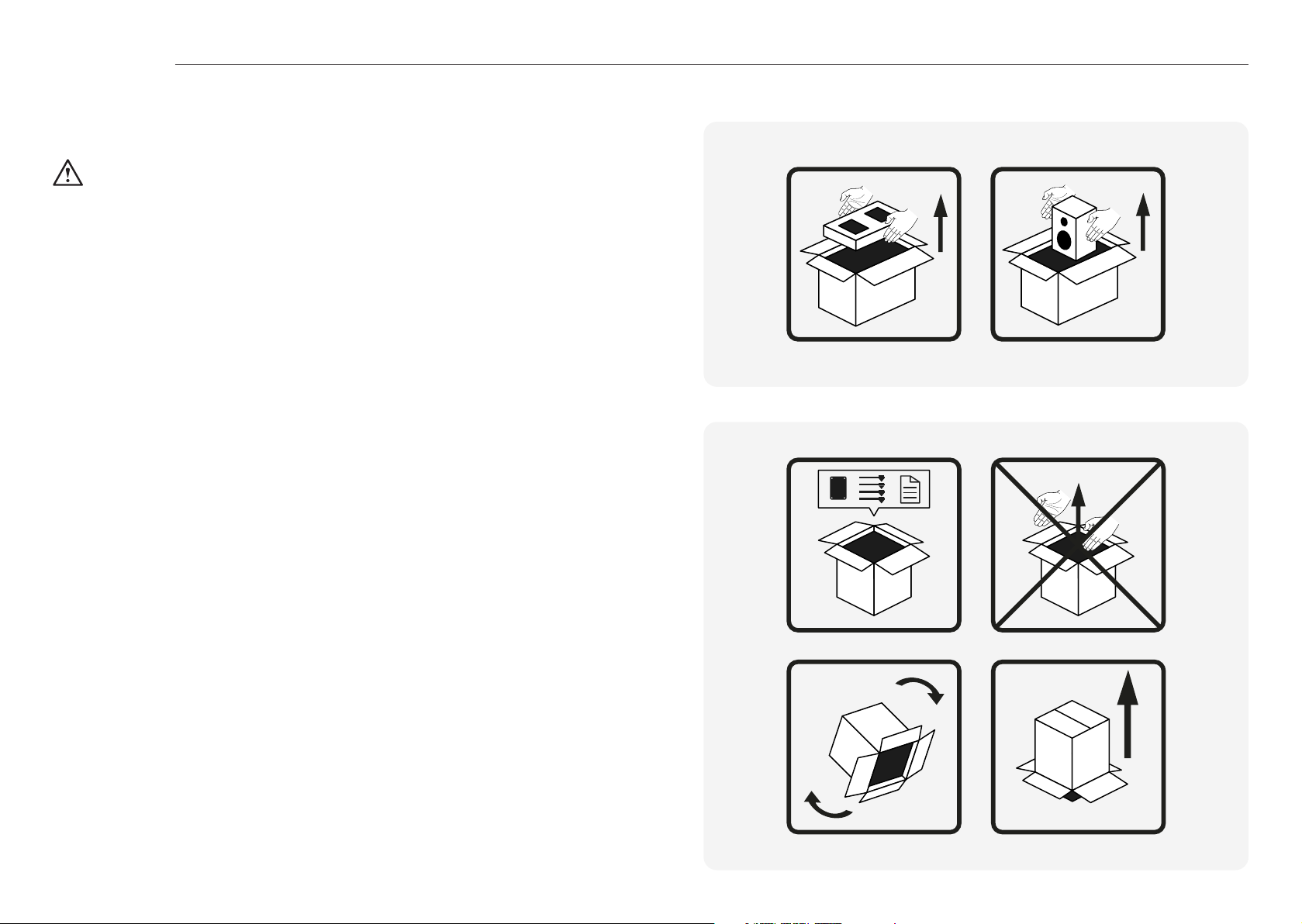
Unboxing
Before you unpack your loudspeakers, please make sure that there is plenty of clean loor area
available.
WARNING: DO NOT attempt to lift any of the loudspeakers alone.
The recommended number of people is printed on the outer carton.
Gold 50, 100 & C250 6G
1. Open the top of the box and remove the cap with the accessories.
2. Lift the speaker(s) out of the box and remaining end cap.
3. Remove the protective bag.
Gold 300 & 500 6G
1. Open the top of the box and remove the end cap with the accessories. The end cap is
used as a jig for assembly of the base plate, outriggers and feet. Ensure to remove all
accessories before construction.
2. Position the outriggers in the end cap, they will form an ‘X’ formation from the corners of
the base, which is then placed onto the outriggers and bolted together using the supplied
bolts (M5). Once assembled remove the base and put the end cap back in the box.
3. Flip the box over and lift up the outer carton.
4. Remove the base end cap (which will currently be facing upwards) and it the assembled
base plate to the speaker using the supplied bolts (M10).
5. Flip over the speaker once more to return it to normal orientation.
6. Remove the remaining end cap and the protective bag.
2 3
Page 4
Attaching feet
Gold 300 & 500 6G feet
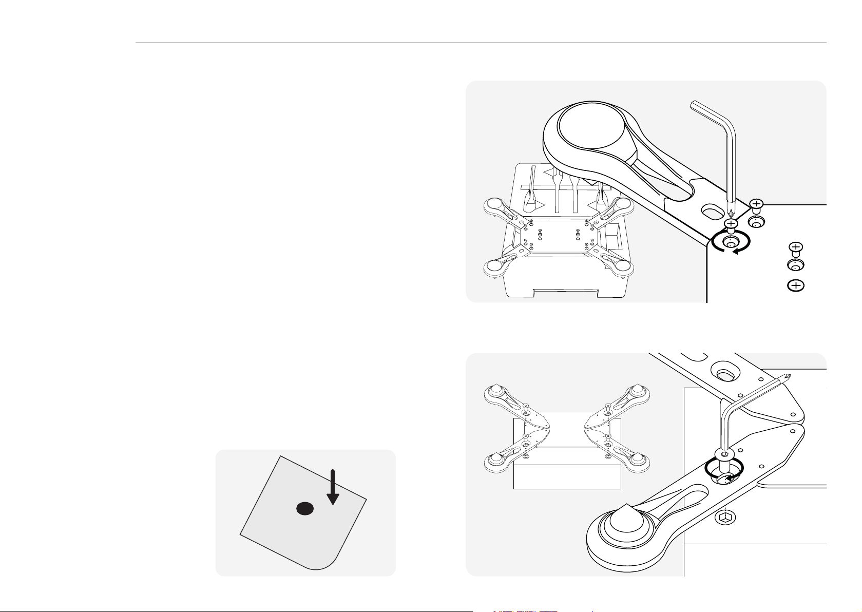
Attaching the foot assembly
The Gold 300 and 500 6G are supplied with a foot assembly that attaches to the bottom of
the cabinet. The top polystyrene end cap from the packaging can be used as a jig for easier
assembly.
Place all 4 feet into the spaces on the jig with the spike facing down. Place the plate on top of
the feet with the soft side facing up.
Secure the feet to the plate with the 12 screws provided, tightening with the included cross
head tool.
Attach the plate to the cabinet with the 4 bolts provided, tightening with the included hex tool.
Gold 50, 100 & C250 6G feet
The Gold 50, 100 and C250 6G come with self
adhesive rubber feet in the packaging.
These should be placed on the underside of
the cabinet in the corners when placing the
speakers on a shelf or when using third party
stands for the speakers. This helps to isolate
the loudspeaker and reduce the chances of it
from moving.
4 5
Page 5
Spikes & feet
Gold 300 & 500 6G feet
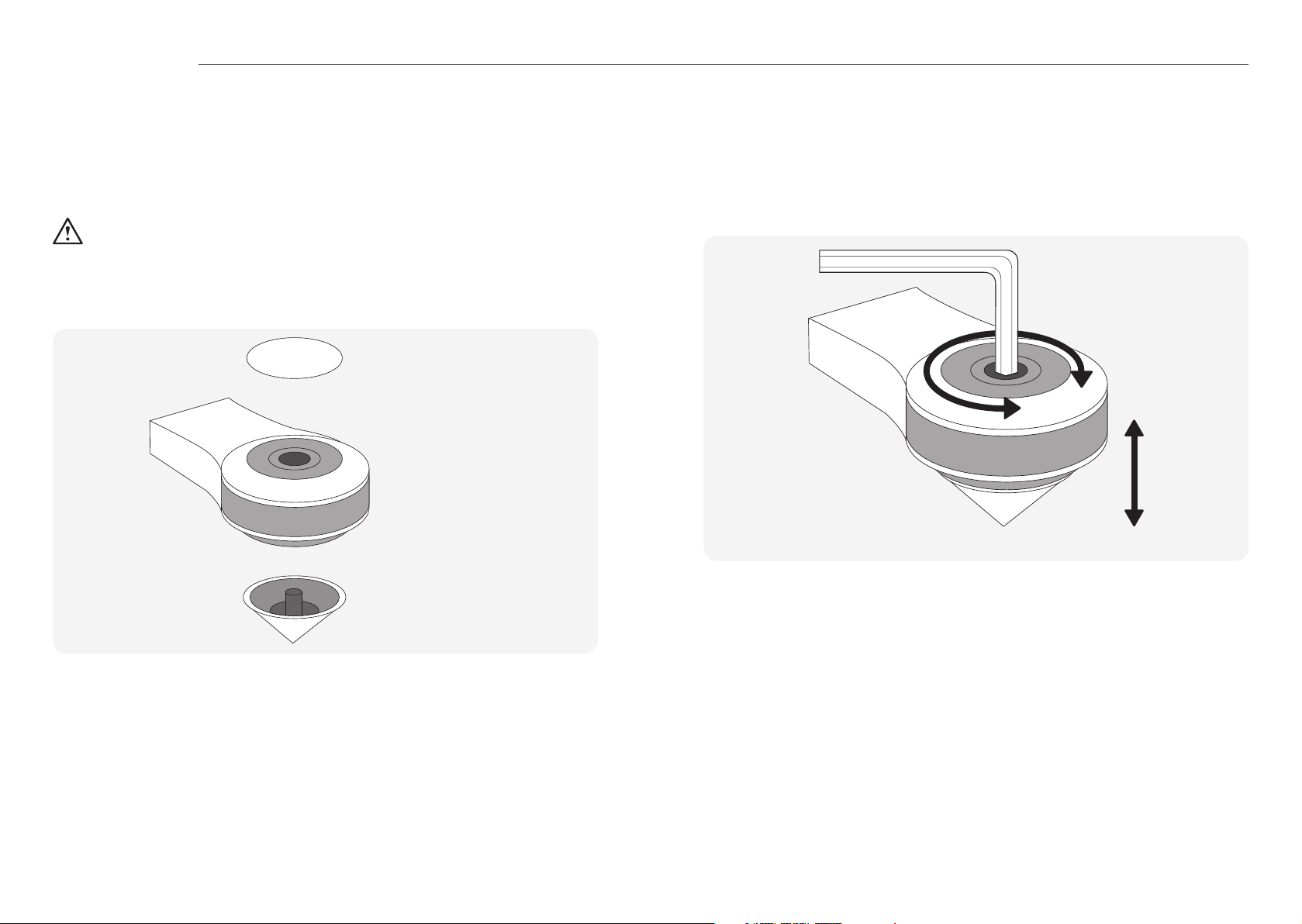
Use on carpeted loors
If the loudspeaker is being installed on a carpeted loor, screw the spike into the foot and
outrigger assembly. Position the loudspeaker in its listening position and check it is level and
stable.
Please ensure there are no hidden wires under the carpet that could be damaged by the
spikes.
Use on wooden or hard loors
If the loudspeaker is being installed on wooden / hard loors or where spikes are inappropriate,
remove the spike from the foot. Position the loudspeaker in its listening position and check it is
level and stable.
Top Cap
Outrigger
(Attached to cabinet)
Rubber Foot
Levelling the speaker
You can check that the loudspeaker is level on all sides by using a spirit level (not supplied). If
it’s slightly uneven, remove the top cap (held in place magnetically) and unscrew the foot at the
lowest point using the supplied Hex key as illustrated below and check again. Continue this
process until the cabinet is fully level, then replace the top cap.
Spike
6 7
Page 6
Setting up your system
2 channel system
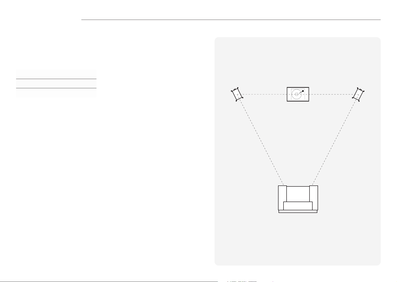
When arranging a 2 channel system, the listening position and the loudspeakers should form an
equilateral triangle. Ideally the loudspeakers should be positioned approximately 6 - 10 feet (1.8
- 3m) apart and a minimum of 3 feet (91cm) from the side walls. The ideal distance from the rear
wall varies depending on the loudspeaker (see list below).
Gold 50 6G 15 - 30 cm / 6 - 12 ”
Gold 100 & 300 6G 20 - 36 cm / 8 - 14 ”
Gold 500 6G 30 - 61 cm / 12 - 24 ”
NOTE: These are recommended distances for optimal performance.
Actual results will vary dependant on room size, construction and personal tastes.
Experimentation is strongly advised when setting up the loudspeakers, as environment and
personal preference will dier with every installation.
If there is insuicient bass for example, try moving your loudspeakers closer to the rear wall.
The opposite approach is recommended if there is excessive bass. Additionally refer to the
information relating to port bungs on page 19.
If stereo imaging is being lost, try ‘toeing’ them in slightly. Sounds that are recorded equally to
each channel should sound as though they come from between the speakers. The angle should
be adjusted to personal tastes, the speakers are designed to be pointed to a point behind the
listener. For a more airy sound point the speakers directly towards the listening position or to
reduce this point them direct forward.
x m
x mx m
8 9
Page 7
Setting up your system
AV positioning
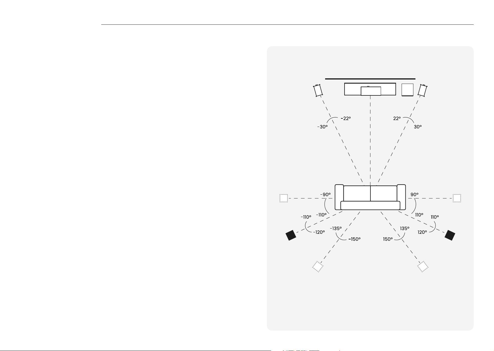
Please refer to the illustration on the right for the ideal angles and positions of each loudspeaker
in your surround system. The loudspeakers should be distanced from the wall according to the
requirements of the loudspeaker, which are listed in the 2Channel Positioning section above.
However, due to AV receiver crossover ilter settings, they may be positioned closer to the wall.
Experimentation is advised.
NOTE: The images are for illustrative purposes only. See diagram on the right.
If setting up a 5.1 system you should place your surrounds in position (A).
If setting up a 7.1 surround system you should place your side speakers in position (B)
and rear loudspeakers in position (C) to create a full 360° soundstage,
If the sound is too bass heavy or there is bass boom from the room when playing music (without a
subwoofer), try moving the loudspeakers slightly further away from the wall(s). In a system with a
subwoofer, try adjusting the crossover frequency settings for the loudspeakers and/or subwoofer
or changing the subwoofer’s position. If placed in a corner, the subwoofer can over excite certain
room modes.
If there doesn’t seem to be much bass from the system, check what the AV receiver has set the
speaker size to. If the loudspeakers have been set to large as part of the auto setup, try setting
them to small, which will send more bass frequencies to the subwoofer. Also check the crossover
frequencies of the loudspeakers and subwoofer as well as the individual channel levels.
The Gold C250 6G centre channel should be positioned so that it is pointing at the viewing
position and at approximate ear height.
BB
A A
C C
5.1 = A
7.1 = B + C
10 11
Page 8
Setting up your system
Dolby Atmos
®
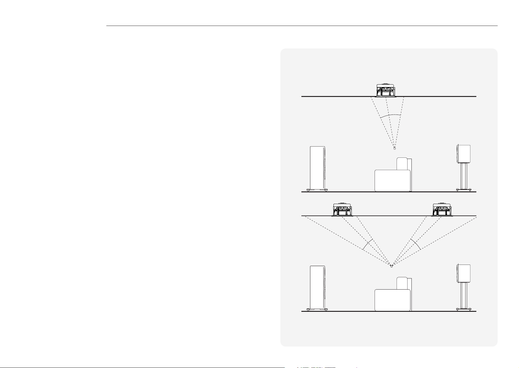
When arranging the overhead channels in a Dolby Atmos® system, we would recommend
using our three-way in-ceiling loudspeakers such as our C3M or C3LA. These employ a unique
midrange / tweeter module, which oers a wider dispersion characteristic, and are ideal for Dolby
Atmos® duties.
Please see the diagram on the right for ideal positioning of 2 or 4 Dolby Atmos® loudspeaker
setups. Typically these would be in line with the front left and right loudspeakers.
65°
80°
100°
Ear Level
45°
30°
55°
125°
135°
150°
Ear Level
12 13
Page 9
Wiring your speakers
Single wiring
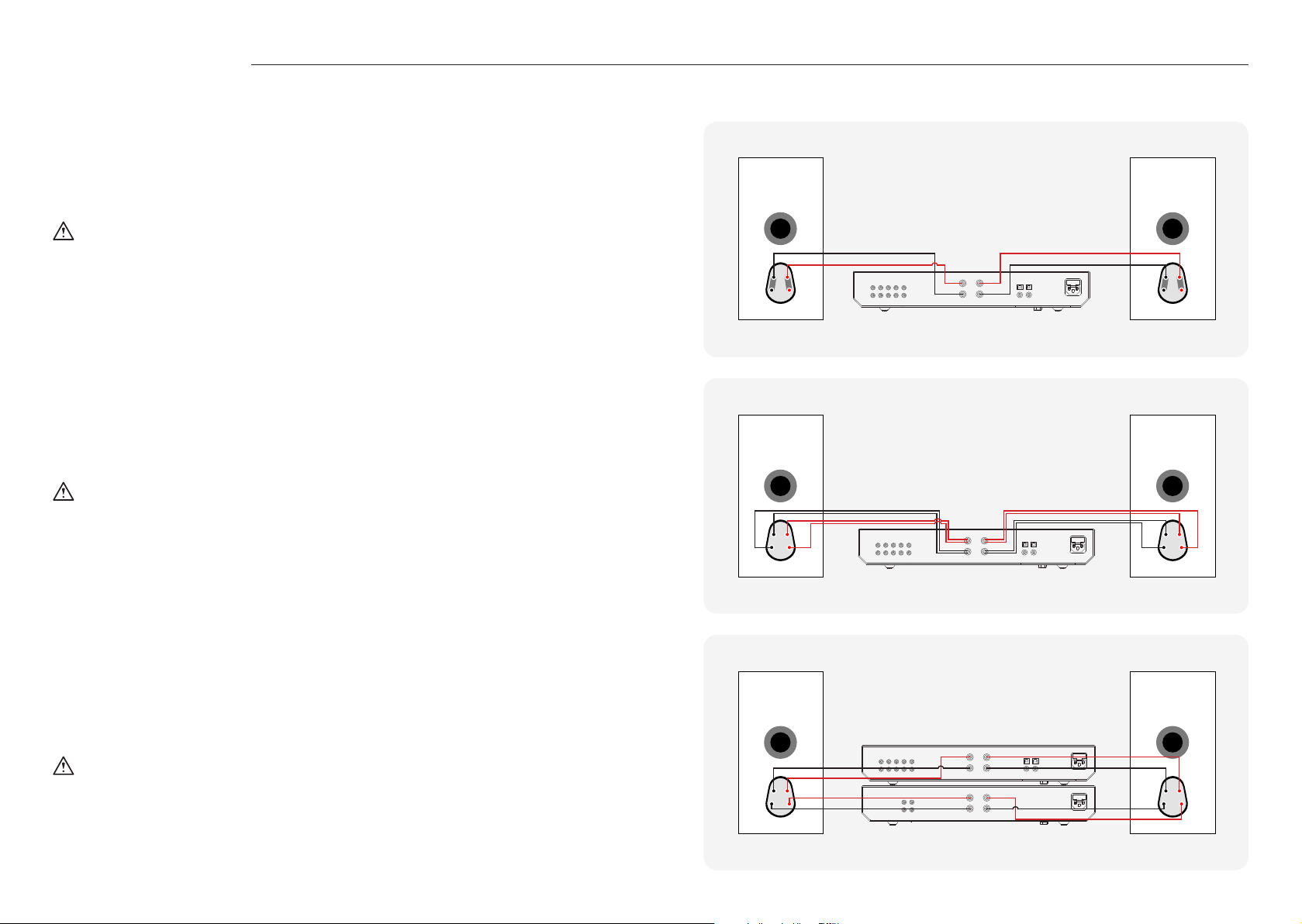
Single wiring is achieved via a single set of cables to the terminals on the back of the loudspeaker.
Internally the loudspeaker crossover guides the frequencies to the appropriate driver/ tweeter.
Low frequencies to the bass drivers, mid frequencies to the mid/bass drivers and high
frequencies to the tweeter.
NOTE: When using this method you must keep the terminal links in place.
Bi-wiring
Bi-wiring is accomplished by connecting separate pairs of loudspeaker cables to the terminals on
the loudspeaker from a single pair of connections on the ampliier. In the case of the Gold Series
6G, the bottom terminals connect to the bass driver(s) and the top terminals connect to the
tweeter in 2 way loudspeakers, or the mid and tweeter in 3 way loudspeakers.
NOTE: When using this method you must REMOVE the terminal links.
Left
RightIntergrated Amplifier
+-+
-
Left
RightIntergrated Amplifier
+-+
-
Bi-amping
Bi-amping is the same as bi-wiring except you are introducing a second amplier into
the equation.
In order to bi-amp you must connect a set of loudspeaker cables to the top terminals
on the loudspeaker from one amplier and another set of loudspeaker cables to the
bottom terminals from the second amplier.
Left
RightIntergrated Amplifier
+-+
NOTE: When using this method you must REMOVE the terminal links.
14 15
-
Left
RightPower Amplifier
+-+
-
Page 10

Using your speakers
Running-in your loudspeakers
Run your loudspeakers in by playing normal music at low-mid listening levels for approximately
5070 hours play time. You may ind the sound will continue to improve even after the 70 hour
mark.
This can be done naturally over time: like a ine wine the performance will improve
with age.
Alternatively if you wish to run the loudspeakers continuously on loop you can decrease the
audible volume/presence by placing the loudspeakers face-to-face so that the drivers/tweeters
are directly aligned and as close as possible. Then connect the ampliier to your loudspeakers so
that one is as normal (in phase): positive to positive and negative to negative (red to red and black
to black), and the other loudspeaker out of phase: positive to negative and negative to positive
inputs on the loudspeaker.
Port Bungs
If the loudspeaker is to be installed in a small room, typically 9 sqM (80 sqFT), or a room known
to reproduce accentuated bass response, it may be desirable to it a port bung in the aected
speaker. However, experimentation is recommended with positioning of the loudspeaker in the
room prior to itting. To optimise performance from the loudspeaker it is important to ensure the
loudspeaker is not positioned too close to a wall or near the corners of a room.
If the positioning of the loudspeaker is predetermined by room aesthetics or layout, you ind you
have accentuated bass or in the case speakers are to be sited in close proximity (less than the
minimum suggested distances of page 2) to a rear wall (such as on a bookshelf, positioned in a
cabinet or on a stand close to a wall), we recommend itting the supplied port bungs to the ports.
With speakers that have 2 ports, such as the Gold 300 & 500 6G, only one port bung should still
be used per speaker.
This will reduce the bass ‘boom’ sometimes termed as overhang, and assist the loudspeakers
to reproduce their best performance under these environmental conditions. ‘Boom’ is
generally caused when bass energy from the loudspeaker ‘excites’ room modes and causes an
accentuation at a particular frequency, or number of frequencies.
When itting port bungs the overall bass extension will not be reduced, however bass energy/
output around the port tuning frequency will be reduced. This has the eect
of reducing bass ‘boom’ while increasing bass clarity and apparent agility.
In all circumstances experimentation is highly recommended.
16 17
Page 11
Care & maintenance
Warranty
Upkeep of cabinets
The inish of the cabinet can be maintained by regular dusting using a soft cloth or micro ibre/
lint-free cloth. If a high gloss inish needs to be revived a high-quality, non-abrasive, automotive
wax or polish can be used. The drive units should only be cleaned with a damp cloth if more than
normal dusting is required.
Never use solvents or aggressive cleaning/polishing agents on your Gold Series 6G loudspeakers.
When in doubt, test the cleaning product on an inconspicuous area on the cabinet and let it sit
for several days before committing to its use on visible portions of the cabinet.
Retention Bolt adjustment
The new Gold Series 6G has a bolt-through driver ixing to reduce cabinet colouration. Each bolt
acts as a rigid brace, but also removes the need for conventional driver ixings as well, eectively
decoupling the driver and front bale to eliminate a further source of resonance.
NOTE: Should this bolt become loose over time, or has worked loose during transit, then please
use the supplied torx key to tighten the bolt back up. This only needs to be a quarter turn after
the strain has been taken by the bolt.
In the unlikely event that there is a defect with this product, it is covered by the Monitor Audio
manufacturer’s warranty, provided that the product was supplied by an authorised Monitor Audio
retail specialist.
For the period of cover please refer to the product page on our website at monitoraudio.com
Register your Monitor Audio speakers
to ensure the best possible product and customer support
Register your speakers using the QR code
or visit monitoraudio.com/registration
18 19
Page 12

Specications
Model Gold 50 6G Gold 100 6G Gold 300 6G
System Format
Sensitivity
(2.83v @ 1m, Free-Field)
Sensitivity
(2.83v @ 1m, Installed)
Recommended
Ampliier Power (RMS
into 4 Ohm, Music
Signal)
Continuous Power
Handling (CTA 426B)
Nominal Impedance
Minimum Impedance
(20Hz to 20kHz)
Drive Unit Complement
Frequency Response
Free-Field (-6dB)
Frequency Response,
In-Room (-6dB)
Maximum Peak SPL
(AES75, Z-weighted)
Bass Alignment
Port Tuning Frequency
Crossover Frequency
External Dimensions
with all accessories
itted(H x W x D)
Weight (each)
2Way 3Way 3W ay
85 dB 86.5 dB 87 dB
N/A N/A N/A
130 – 300 W 130 – 500 W 130 - 500 W
150 W 250 W 250 W
4 Ohms 4 Ohms 4 Ohms
4.0 Ohms @ 225 Hz 3.9 Ohms @ 140 Hz 3.9 Ohms @ 165 Hz
1 x 6” (152 mm) HDT CCAM Bass-Mid
Drivers
1 x MPD III Tweeter
55 Hz - 60 kHz 49 Hz – 60 kHz 45 Hz – 60 kHz
44 Hz - 60 kHz 32 Hz – 60 kHz 28 Hz – 60 kHz
114 dB 119 dB 117 dB
HiVe II Ported HiVe II Ported HiVe II Ported
50 Hz 38 Hz 35 Hz
LF/HF: 2.5 kHz LF/MF: 700 Hz
320 x 185 x 303 mm
(12 5/8 x 7 5/16 x 11 15/16”)
8.5 kg (18 lb 12 oz) 14 kg (30 lb 14 oz) 21.2 kg (46 lb 12 oz)
1 x 8” (203 mm) HDT CCAM Bass Drivers
1 x 3” (76 mm) HDT CCAM Mid-Range
Driver
1 x MPD III Tweeter
MF/HF: 2.6 kHz
447.7 x 230 x 357.3 mm
(17 15/8 x 9 1/16 x 14 1/16”)
2 x 6” (152 mm) HDT CCAM Bass Drivers
1 x 3” (76 mm) HDT CCAM Mid-Range
Driver
1 x MPD III Tweeter
LF/MF: 800 Hz
MF/HF: 2.7 kHz
1098 x 339 x 463 mm
(43 1/4 x 13 3/8 x 18 1/4”)
Model Gold 500 6G Gold On-Wall 6G Gold C250 6G
System Format
Sensitivity
(2.83v @ 1m, Free-Field)
Sensitivity
(2.83v @ 1m, Installed)
Recommended
Ampliier Power (RMS
into 4 Ohm, Music
Signal)
Continuous Power Handling (CTA 426B)
Nominal Impedance
Minimum Impedance
(20Hz to 20kHz)
Drive Unit Complement
Frequency Response
Free-Field (-6dB)
Frequency Response,
In-Room (-6dB)
Maximum Peak SPL
(AES75, Z-weighted)
Bass Alignment
Port Tuning Frequency
Crossover Frequency
External Dimensions
with all accessories
itted(H x W x D)
Weight (each)
3Way 2Way 3 Way
88.5 dB N/A 87.5 dB
N/A 88 dB N/A
130 – 600 W 130 – 300 W 130 – 500 W
300 W 150 W 250 W
4 Ohms 4 Ohms 4 Ohms
4.0 Ohms @ 150 Hz 5.3 Ohms @ 200 Hz 3.9 Ohms @ 165 Hz
2 x 8” (203 mm) HDT CCAM Bass Drivers
1 x 3” (76 mm) HDT CCAM Mid-Range
Driver
1 x MPD III Tweeter
44 Hz – 60 kHz N/A 64 Hz – 60 kHz
25 Hz – 60 kHz 38 Hz – 60 kHz 54 Hz – 60 kHz
122 dB 115 dB 121 dB
HiVe II Ported Ported Sealed
33 Hz 44 Hz N/A
LF/MF: 700 Hz
MF/HF: 2.6 kHz
1155 x 383 x 475 mm
(45 1/2 x 15 1/16 x 18 11/16”)
26.5 kg (58 lb 7 oz) 9 kg (19 lb 14 oz) 15.3 kg (33 lb 12 oz)
1 x 6” (152 mm) HDT CCAM Bass-Mid
Drivers
1 x MPD III Tweeter
LF/HF: 2.5 kHz LF/MF: 800 Hz
465 x 300 x 124.2 mm
(18 5/16 x 11 13/16 x 4 7/8”)
2 x 6” (152 mm) HDT CCAM Bass Drivers
1 x 3” (76 mm) HDT CCAM Mid-Range
Driver
1 x MPD III Tweeter
MF/HF: 2.7 kHz
205 x 537 x 335 mm
(8 1/16 x 21 1/8 x 13 3/16”)
20 21
Page 13

Listen Again.
Monitor Audio Ltd.
24 Brook Road
Rayleigh, Essex
SS6 7XJ
England
Tel: +44 (0)1268 740580
Email: [email protected]
monitoraudio.com
©Monitor Audio Ltd. | V12023 - Gold Series 6G
 Loading...