

Moniteq Crypto Lock CC-8521BN Instruction Manual
1
Crypto Lock
CC-8521BN
7/17
Access Control System
INSTRUCTION MANUAL
MONITEQ, Inc.

2

3
Table of Contents
1. INTRODUCTION ................................................................................................................................ 4
2. SPECIFICATIONS .............................................................................................................................. 6
3. SUPPLIED EQUIPMENT ................................................................................................................... 7
4. FUNCTIONS OF CONTROLS AND INDICATORS ........................................................................ 7
4.1 KEYPAD ......................................................................................................................................... 7
4.2. CONTROL PANEL ....................................................................................................................... 7
5. INSTALLATION .................................................................................................................................. 8
5.1 GENERAL ...................................................................................................................................... 8
5.2 INSTALLATION PROCEDURE ................................................................................................... 8
5.3 POWER SUPPLY SETTINGS ....................................................................................................... 9
6.1 PROGRAMMING ............................................................................................................................ 11
6.1 GENERAL .................................................................................................................................... 11
6.2 PROGRAMMING INSTRUCTIONS ........................................................................................... 11
6.2.1 INITIAL SETTINGS ............................................................................................................. 11
6.2.2 PIN MANAGEMENT ............................................................................................................ 11
6.2.3 DOOR MONITORING .......................................................................................................... 12
7. OPERATION ..................................................................................................................................... 13
8. KEY PAD INSTALLATION TEMPLATE ........................................................................................ 15
9. CONTROL PANEL MOUNTING DIAGRAM ................................................................................. 17
4
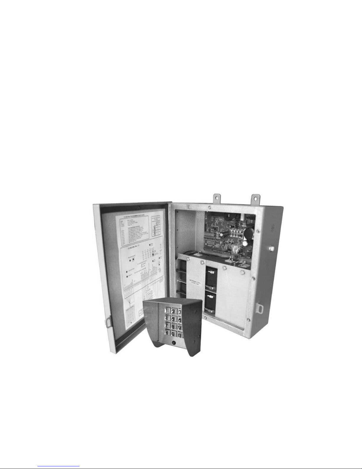
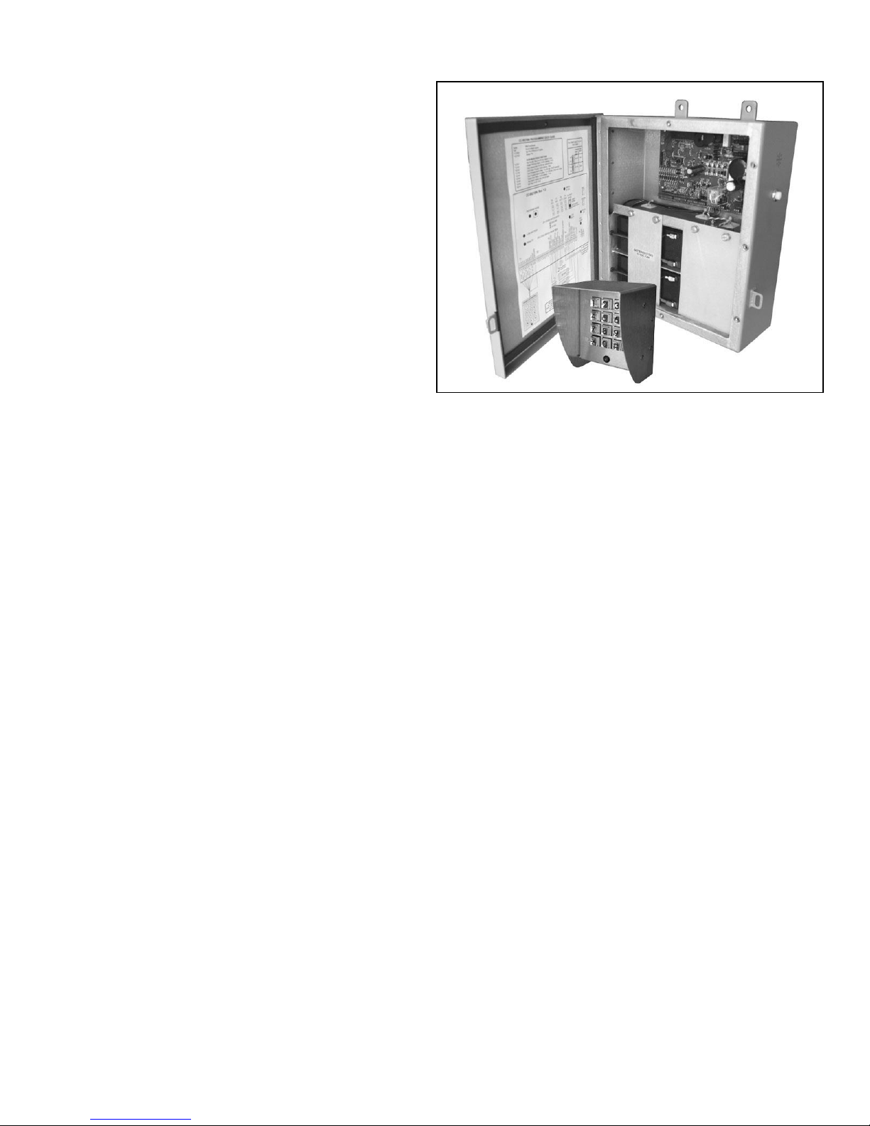
Figure 1-1, the CC-852BN Control Panel and Keypad
1. INTRODUCTION
Crypto-Lock is a versatile, easily installed
and operated single door access control
system. It provides reliable, secure access
control using a single 3, 4, 5 or 6-digit PIN
code for all users. It can be used with
virtually all magnetic locks and electric
locks and door strikes.
The system, pictured in Figure 1-1,
includes a built-in 24Vdc power supply to
power electric and magnetic locks,
eliminating the need for a separate power
supply unit. It provides the voltages and
currents required to reliably open standard
locking devices including heavy duty locks
such as Sargent & Greenleaf BRUTE*
electric locks that require high in-rush
currents.
The power supply includes a battery
charging and monitoring circuit that
automatically maintains batteries in a fully
charged condition and activates audible
and visual warnings when the charge level
is low. Two 12V, 7AH sealed lead acid
batteries are housed in the Control Panel.
The length of time during which the lock
remains released after entry of the valid
PIN is programmable from 3 to 60
seconds. An invalid PIN “Penalty” feature
provides for ignoring all keypad entries for
3 to 60 seconds after an invalid digit is
entered. Further, if five or more successive
invalid PINs are entered the penalty time is
set to 60 seconds until the valid PIN is
entered. This greatly reduces the
possibility of gaining access by guessing
PIN codes.
The system provides door monitoring
functions through programmable alarms
that can be used to notify of a door that
has been propped or forced open. Alarms
can trigger audible alerts or activate
signals for use with external devices or
systems. The keypad is weather resistant
chrome and stainless steel unit with a 20 ft
shielded, water blocking cable. A green
LED on the face the keypad signals the
recognition of each key stroke and also
illuminates when the door is released.
The # button on the keypad activates a
horn in the control Panel and also
generates an output signal for activating an
external 24Vdc device.
Installation and set-up are readily
accomplished using the wiring diagram
affixed to the inside of the enclosure door
and also contained in this manual.
A programming mode (which can only be
activated from within the Control Panel)
allows authorized personnel to set the PIN
and other functions (see Table 5-1) using
the keypad.
A typical installation of the Crypto Lock is
illustrated in Figure 1-2.
*Brute is a registered trademark of Sargent &
Greeleaf, Inc.

5
CC-8521BN
CRYPTO-
LOCK
Versatile lock power:
* 24Vdc @ 2A
* High in-rush current capacity
* Holding current limiting protects lock
115Vac, 50/60Hz
Electric lock or
strike
(fail-secure)
Programed
Alarm/Horn
Output
KEYPAD WITH
STATUS LED
REMOTE
RELEASE BUTTON
(not supplied)
Door sensor
Stand-by
Batteries
Built-in Horn and
Release Buttom
Ship's Central
Alarm System
Output
Features:
* 3, 4, 5, or 6-digit PIN
* Adjustable open duration
* Block after invalid PINs
* Door Propped Alarm
* Forced Door Alarm
* Anti Follow Through
Figure 1-2, Typical Installation of the Crypto Lock Access Controller

6
2. SPECIFICATIONS
Power required: 115 Vac, 50 or 60 Hz,
25W
Lock Output: 24 Vdc, 2A continuous, 16A
in-rush current
Horn Output: 24 Vdc
Battery back-up: 24Vdc, automatic
transfer and charging (batteries optional,
Moniteq Type CC-BATT)
Battery monitoring: Warning lamp,
beeper and output signal activate when
battery is low
PIN code length: 3, 4, 5 or 6 digits
Open duration: Programmable, 3 to 60
seconds
Penalty function: Invalid PIN attempts
temporarily disable operation and can be
set to sound an alarm.
Penalty time: Adjustable, 3 to 60 seconds,
set to 60 seconds after five invalid PIN
attempts
Remote release input: Dry contact
closure
Door monitoring functions: Door
propped open alarm, forced door alarm,
anti-tailgating.
Keypad
Dimensions: 4.625H x 3.625W x 3.5D in.,
Weight: 3 Lbs. (with supplied 20 ft. cable)
Cable: Type LSC5OSW-4, 8-cond., #24
Enclosure: 0.09” welded aluminum, RF
gasketed door, powder coated, gray color,
hasp for padlock (not included)
Dimensions: 12H x 9W x 4.5D in.,
Weight: 13 Lbs. (without batteries)
Mounting: Use 3/8” x 1” long studs on
bulkhead with centers located on a 14.75 H
x 5.28 W inch rectangular pattern.
Options available:
CC-BATT: 12Vdc, 7AH rechargeable
battery (two required for 24Vdc operation)
CC-BRUTE: Surface mounted electric lock
 Loading...