

CRYPTO-LOCK
Model CC-8521B
Access Control System
Instruction Manual
Ed. 11/17
Moniteq, Inc.

2

Table of Contents
Introduction ........................................................................................................................................... 4
Specifications ........................................................................................................................................ 6
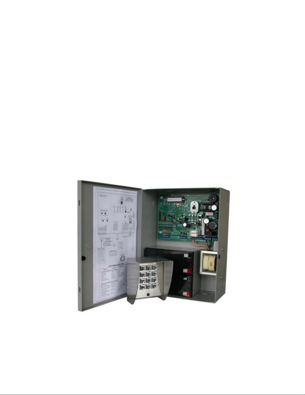
Supplied Equipment .............................................................................................................................. 7
Functions of Controls and Indicators ..................................................................................................... 8
KEYPAD ............................................................................................................................................ 8
PROGRAMMING MODE ................................................................................................................... 8
CONTROL UNIT ............................................................................................................................... 8
Installation ............................................................................................................................................. 9
Setup .................................................................................................................................................. 10
Programming ...................................................................................................................................... 12
Operating Procedure ........................................................................................................................... 14
Limited Warranty ................................................................................................................................. 16
3

Introduction
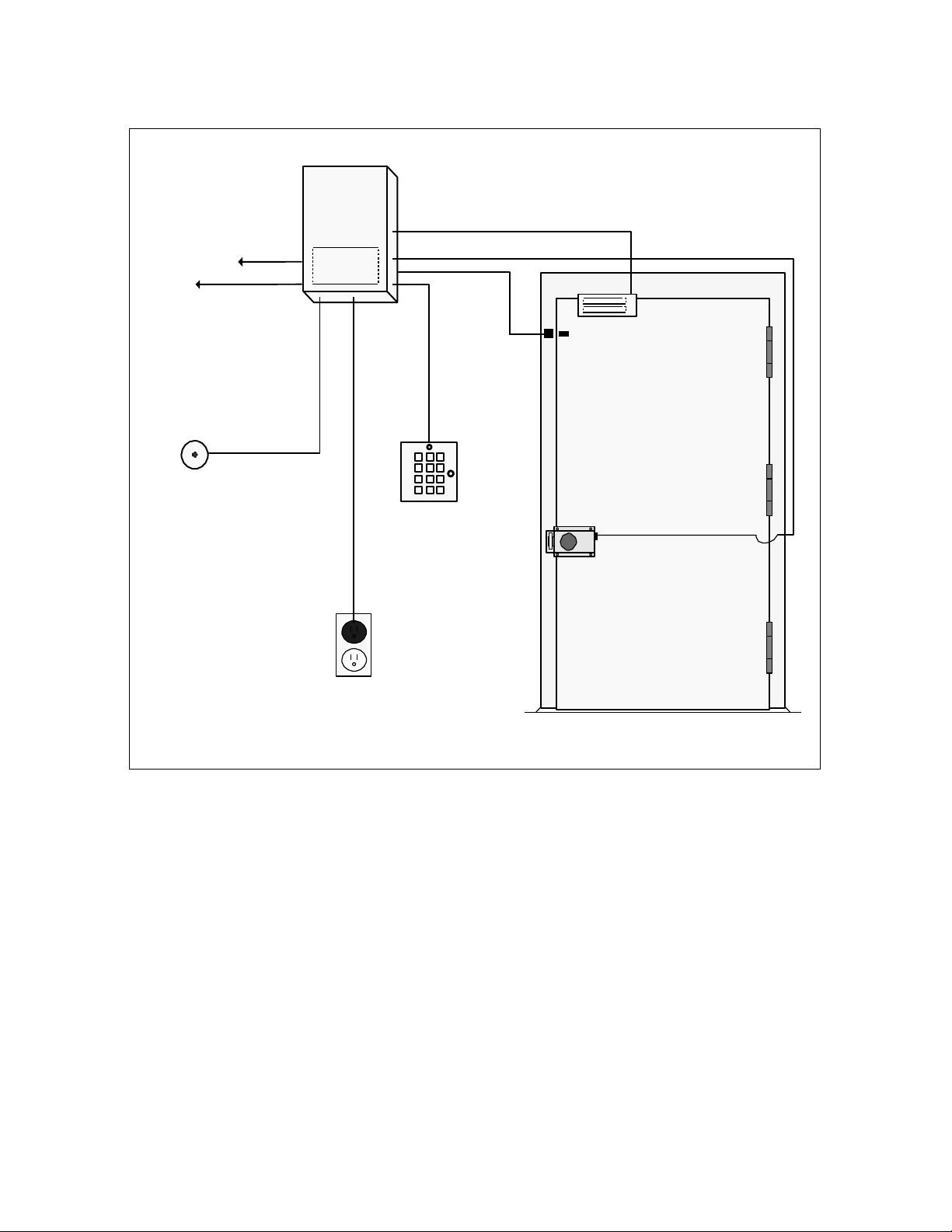
The Crypto-Lock Model CC-8521B is a single door access control system providing
keypad control using a single 3-6 digit PIN code. It can be used with most magnetic
and electric strikes, including doors with both features. Typical installation is illustrated
in Figure 1. A wiring diagram is affixed to the interior of the control unit door and in
figure 2 of this manual.
The system includes a built-in 12VDC and 24VDC, 4A power supply to power electric
strikes and magnetic locks, eliminating the need for a separate power unit. It provides
adequate power to reliably open heavy-duty locking devices such as Von Duprin* rim
latch retraction units and Sargent & Greenleaf Brute* electric locks. The control unit
can house two optional 12V, 7AH sealed lead acid batteries (not included) and
maintain them at full charge. Audible and visual warnings will occur when the charge
level is low.
Security features include anti-follow, propped and forced door alarms, invalid PIN
penalty delays and adjustable time durations of lock release after entry of a valid PIN
code. A release button (not provided) can be used to remotely unlock the door from a
location on the secure side of the door.
The weatherproof, 10-button, stainless steel, spy-proof keypad unit includes a green
LED which illuminates when the lock is released. A # button on the keypad activates
an annunciator in the control unit and generates output signal for an optional external
audio or visual device (not included).
*Von Duprin is a registered trademark of the Ingersoll-Rand Company; Brute is a registered trademark of
Sargent & Greenleaf, Inc.
4
CC-8521B
CRYPTO
-LOCK
Low Battery
Warning Output
Stand-by
Batteries
External
Annunciator
Output
Magnetic Lock
(fail-safe)
Release
Button
Keypad with
Electric Lock or Strike
(fail-secure)
115/230 Vac,
50/60Hz
Figure 1, Typical Installation
Door
Switch
Status LED
5

Specifications
Power Required
115 or 230VAC, 50 or 60Hz, 25W
Output
12VDC or 25 VDC, 4A continuous
In-rush Current Capacity
16A
Relay Contacts
10A, SPDT (Form C)
Battery Backup
12VDC or 24VDC, automatic transfer and
charging (batteries optional)
Enclosure Description
19 gauge steel, powder coated paint, gray
color, knockouts for conduit and cam lock
(included), holes to accommodate padlock (not
included)
Enclosure Dimensions
12H x 9W x 4.5D in.
Optional Equipment Available
CC-BATT (2 required), CC-BRUTE
6

Supplied Equipment
QTY
ITEM
PURPOSE
1
Control Unit
Main Processor and Power Supply
1
Keypad with 15’ Cable
Accepts PIN Code Entries
1
Manual, Crypto-Lock CC-8521B
Installation and Operating Instructions
1
Keypad Mounting Template
Keypad Installation
1
Line Cord with U.S. 3-prong plug, 10 ft.
Connection to AC Power
2
Threaded Rod, #8 x 12”
Keypad Mounting, Thru-wall
1*
Cam lock w/ Two Keys
Lock Control Unit Door
2*
Screw, Slotted, Sheet Metal, #6, ½”
Hold Control Unit Door Closed
2*
Battery Cables, #18 AWG, Black/Red
Connect Batteries to Board
2*
Fuse, 5 x 20MM, 4A, Slo-Blo
Spares
4*
Hex Nut, #8
Keypad Mounting
2*
Acorn Nut, #8
Keypad Mounting, Thru-wall
6*
Lock Washer, #8
Keypad Mounting
2*
Washer, #8, 1 ¼” dia.
Keypad Mounting, Thru-wall
8*
Pan head Combo Drive Screw, #8 x 1
½”
Keypad and Control Unit Mounting
2*
Bushing, Black Nylon, 7/8”
Protects Cable Entering Control Unit
2*
Vent Plug, Black Nylon, 7/8”
Control Unit Ventilation
2*
Anchor, Nylon, Adhesive Back, 1” x 1”
Secure Cables within Control Unit
6*
Tie Wrap, Nylon, 4”
Secure Cables within Control Unit
*Items packed in poly bag
7

Functions of Controls and Indicators
KEYPAD
Normal Operation Mode
Keys 1 through 0: enter PIN code
# Key: sound annunciator in Control Unit and activate 12VDC output signal for use with
external device (not included)
* Key: not used
Green LED: illuminates when correct PIN code has been entered and door is released;
flashes when any key is pressed
PROGRAMMING MODE
Keys 1 through 0: enter programming codes
# Key: terminate the programming mode
* Key: delimiter for programming codes and parameters
Green LED: flashes continuously, single flash for valid programming entry, three
flashes for invalid programming entry
CONTROL UNIT
Penalty LED: illuminates when invalid PIN penalty feature is activated
AC Power LED: illuminates when the system is AC powered
Battery Power LED: illuminates when the system is battery powered
Output Voltage Switch (24 or 12V): selects voltage to operate attached locking devices
Output Mode Switch (direct or limit holding current): direct provides up to 4A of
continuous holding current, limit holds current to approximately 300 mA after locking
device energizes (limit setting permits holding an electric lock or strike open without
damaging its solenoid, will only operate when output voltage switch is set to 24V)
Low Battery LED: illuminates when the battery is low
Alarms: varies, see Alarm Sequences, page 12
F6: 12VAC power
F4: 24VDC power
F5: Lock
F3: Batt
8

Installation
WARNING: DO NOT CONNECT AC POWER CORD TO POWER SOURCE UNTIL
ALL SET UP IS COMPLETE!!! Consult Figure 2 for installation.
1) Mount the keypad approximately 36 to 44 inches above the floor on the unsecured
side of the door. Use the keypad installation template to mark and drill holes. Throughwall mounting can be accomplished using the #8 threaded rod, acorn nuts, hex nuts,
lock washers and 1 ½” washers. Alternatively, the keypad can be mounted using four
of the supplied #8 x 1 ½” pan head combo drive screws.
2) Mount the electric lock, strike or magnet according to manufacturer instructions.
3) Mount the control unit on the secure side of the door in an area convenient to the
door and electrical outlet. Four #8 x 1 ½” pan head combo drive screws are provided.
4) If required, install the supplied cam lock in the knockout hole provided for that
purpose (on the enclosure door). Alternatively, if a padlock (not included) is to be used,
remove the two 3/8” nylon plugs from the padlock holes. The padlock’s shackle must
be first inserted through the hole on the side of the enclosure; the door can then be
closed so that the padlock hole on the door also passes over the shackle. If the door
does not need to be locked, the two supplied #6 x ½” screws can be used in the holes
on the door edge to hold it closed. Note: all cables passing through the knockout holes
in the enclosure must be protected from chafing using the supplied 7/8” nylon
grommets. Route all cables to avoid the space in the bottom of the control unit that can
be occupied by batteries. Securing components are supplied for this purpose.
5) Connect the keypad to the control unit by color. Fifteen feet of cable is supplied with
the keypad. The keypad can be located up to 1,000 feet from the control unit using
additional cable (10 conductors, #22 required).
6) Connect the electric lock, strike or magnet.
7) If used, connect the release button (not included) and external 12VDC annunciator
(not included, 2 conductors, #22 required). Note that an internal annunciator on the
Logic Board will sound when the keypad’s annunciator button is pressed.
8) If using the propped or forced door alarms, connect a door switch (not included).
9) Install and connect the optional batteries using the two supplied battery cables. Use
only 12V, 1.2 to 7AH rechargeable sealed lead acid batteries (Part # CC-BATT).
10) Connect the AC power cord to T4 according to the available voltage
(115/230VAC).
11) Connect the transformer wires to T3 according to the available voltage
(115/230VAC). CAUTION: The control unit is factory wired for 115VAC operation.
9

Setup
1) Set the Output Source switch (S2) to 12 or 24VDC as dictated by the voltage rating
of the lock being used. If both lock types are being used, they must have the same
voltage rating.
2) Set the Output Mode switch to LIMIT when used with Brute electric lock or a similar
heavy-duty solenoid operated lock. Set this switch to DIRECT when used with
standard electric strikes or magnetic locks.
3) Connect the power cord to an appropriate source of AC power and verify that the
Power LED illuminates.
4) Enter the valid PIN code on the keypad and verify that the lock releases and that the
green LED on the keypad illuminates.
10
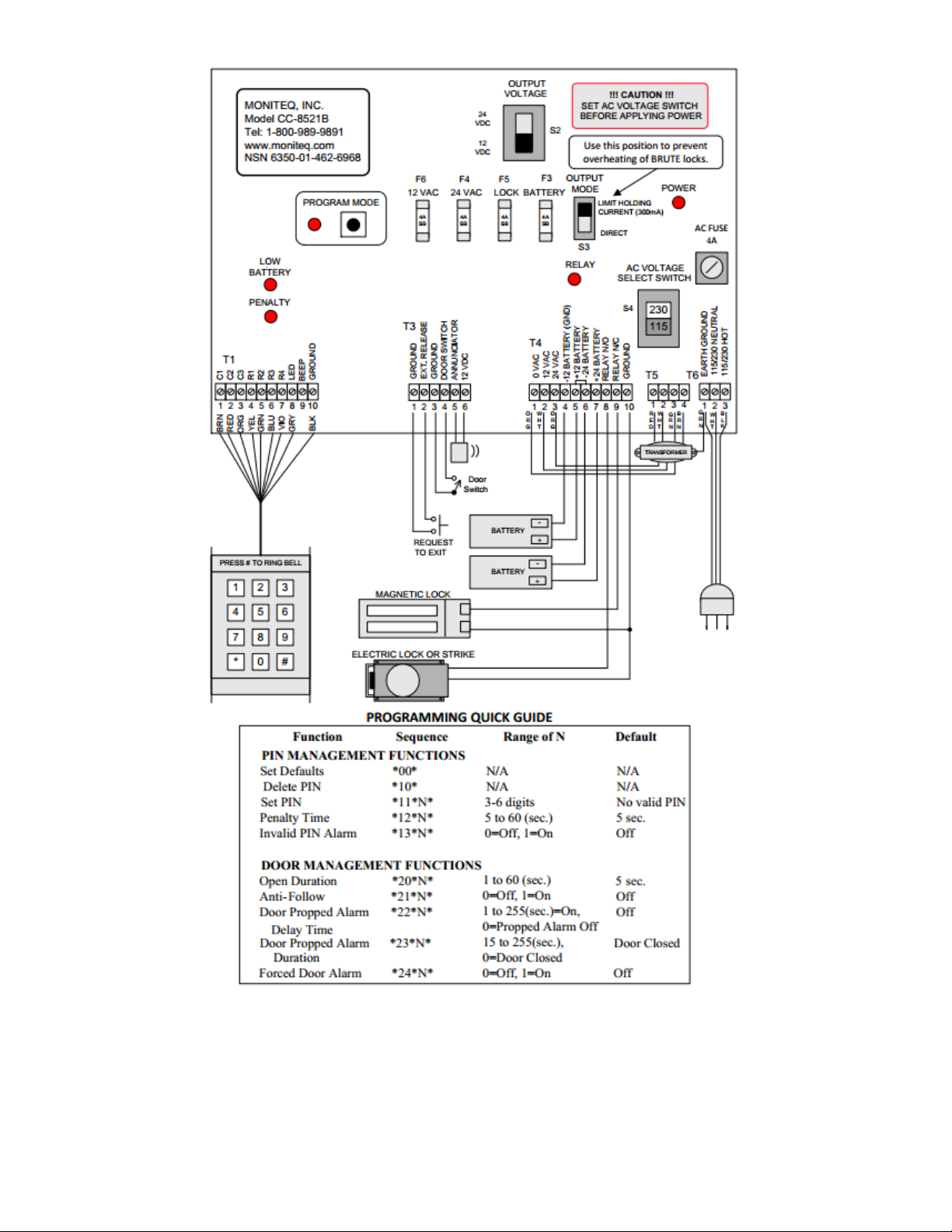
Figure 2, Wiring Diagram
11

Programming
Function
Sequence
Range of N
Default
PIN Management Functions
Set Defaults
*00*
N/A
N/A
Delete PIN
*10*
N/A
N/A
Set PIN
*11*N*
000 to 999, 9999, 99999 or
999999
No valid PIN
Penalty Time
*12*N*
5 to 60 (seconds)
5 seconds
Invalid PIN Alarm
*13*N*
0=off, 1=on
Off
Door Management Functions
Open Duration
*20*N*
1 to 60 (seconds)
5 seconds
Anti-Follow
*21*N*
0=off, 1=on
Off
Door Propped Alarm Delay
*22*N*
0=off, 1 to 255
(seconds)=on
Off
Door Propped Alarm Duration
*23*N*
0=door closed, 15 to 255
(seconds)
Door closed
Forced Door Alarm
*24*N*
0=off, 1=on
Off
Enter the programming mode by pressing the PROGRAM MODE button inside the
control unit. The red program LED in the control unit and the green LED on the keypad
will both flash to verify that the programming mode is active. To exit programming,
press the PROGRAM MODE button again or the # key on the keypad. Alternatively,
the system will revert to normal mode if no keys are pressed for 5 minutes.
Initial Settings: During a new installation or if existing settings are unknown, it is
recommended that the default values for all PIN and door monitoring settings be reset
by entering *00* on the keypad.
PIN Management: A new valid PIN code can only be set when the system is in the
programming mode. To establish a new valid PIN, enter *11*N*, where N is any
number containing 3-6 digits. To delete the current valid PIN, enter *10* to effectively
disable the keypad since no PIN entry can be used to release the door.
Penalty Delays: An invalid PIN penalty feature protects against an unauthorized user
gaining entry by entering successive guesses of the correct PIN. When an invalid PIN
is entered, the system then ignores all further PIN entries for 5 to 60 seconds. The
default value is 5 seconds. To change the penalty time, enter *12*N*, where N is from
5 to 60. After five successive invalid PIN entries, the penalty time is automatically reset
to 60 seconds until the valid PIN is entered. This feature increases the average time it
would take to successfully guess the valid PIN and is particularly effective in protecting
12

PINs with only 3 or 4 digits. An invalid PIN alarm feature sounds an alarm (three short
beeps) whenever an invalid PIN is entered. This feature is disabled by default. To
enable, enter *13*1*. To disable, enter *13*0*.
Door Monitoring: The system includes a number of functions that make it possible to
monitor the status of the door during operation. With the exception of the open duration
function, these features require that a door position switch (not included) be installed
on the door and connected to the control unit.
Open Duration: The open duration is the time period during which the door is released
(unlocked) after either a valid PIN is entered on the keypad or the remote release
button is pressed. The default open duration time is 5 seconds. To change the open
duration time, enter *20*N*, where N is from 1 to 60.
Anti-Follow: The anti-follow mode is provided to prevent the door from being re-opened
a second time during the open duration time period. This function is disabled by
default. To enable anti-follow, enter *21*1*. To disable anti-follow, enter *21*0*. When
this function is enabled, the door re-locks immediately after it closes, regardless of the
open duration setting.
Door Propped Alarm: The door propped alarm function sounds an alarm when the door
remains open for more than a specified time or until the door is closed. This function is
disabled by default. To enable the door propped alarm, set the door propped alarm
delay time by entering *22*N*, where N is 1 to 255. To disable the door propped alarm,
enter *22*0*.
Door Propped Alarm Duration: The door propped alarm duration can be set to sound
continuously either until the door closes or until a time out period expires. Enter
programming code *23*0* to set the door propped alarm to sound until the door closes.
To have the door propped alarm sound until a time out period expired or the door
closes (whichever occurs first), enter *23*N*, where N is 15 to 255.
Forced Door Alarm: The forced door alarm function sounds an alarm if the door is
opened without being released by the system. This function is disabled by default. To
enable the forced door alarm, enter *24*1*. To disable the forced door alarm, enter
*24*0*. The forced door alarm is silenced by entering the valid PIN on the keypad or by
disabling the forced door alarm function by entering programming code *24*0*.
13

Operating Procedure
Alarm Type
Alarm Sequence
Silenced By
Visitor
Activated by # button on keypad
Invalid PIN
- - - - -
Five short beeps
After five short beeps
Door Propped
____ ____ ____
Continuous long
beeps
Door closed or time out
set by code *23*N*
Forced Door
- - - - - - - - - - - - - - - -
Continuous short
beeps
Valid PIN or code *24*0*
Low Battery
- - - - - - -
Chirp every 15
seconds
Apply AC power
To operate the CC-8521B, enter the valid 3-6 digit PIN code on the keypad. When the
valid PIN code is entered, the green LED on the keypad will illuminate and the door
lock will release.
The keypad has a build-in visitor annunciator button. Pressing the # button causes an
annunciator to sound in the control unit. If an external audio or visual device is
connected, it will also activate when this button is pressed.
If an incorrect PIN code is entered, the system will enter a penalty mode and will not
recognize any digits for the programmed 5-60 seconds. If five successive invalid PINs
are entered, the penalty time is set to 60 seconds until the valid PIN is entered. After
the penalty time has elapsed, the unit will return to normal operation and entering the
valid PIN code on the keypad will release the door.
If the external release button has been installed, it can be used by an attendant to
release the lock from a location on the secure side of the door.
Diagrams and schematics are available on www.moniteq.com.
Various alarm situations activate different sequences of sounds on the alarm in the
control unit. If an external audio device is connected to the system, it will sound the
same sequences as the alarm in the control unit. The table below lists these alarm
sequences and their meaning.
14

15

Limited Warranty
Moniteq, Inc.
Tel: 1-410-827-8870
1-800-989-9891
Fax: 1-410-827-8875
213 Church Street
info@moniteq.com
Greensboro, MD 21639
www.moniteq.com
Moniteq, Inc. products are warranted to be free from factory defects for a period of one
year from the date of shipment. The repair or replacement of a defective part shall be
at the option of the factory when the product is shipped, prepaid and insured, by the
owner. This warranty is void in cases of abuse, misuse, mishandling, modification, or
repair by unauthorized persons. This warranty is given in lieu of all other warranties
expressed or implied. Moniteq, Inc. is not liable for incidental or consequential
damages resulting from the operation or failure of this product. This warranty
recognizes any and all rights you may have under appropriate state law.
16
 Loading...