

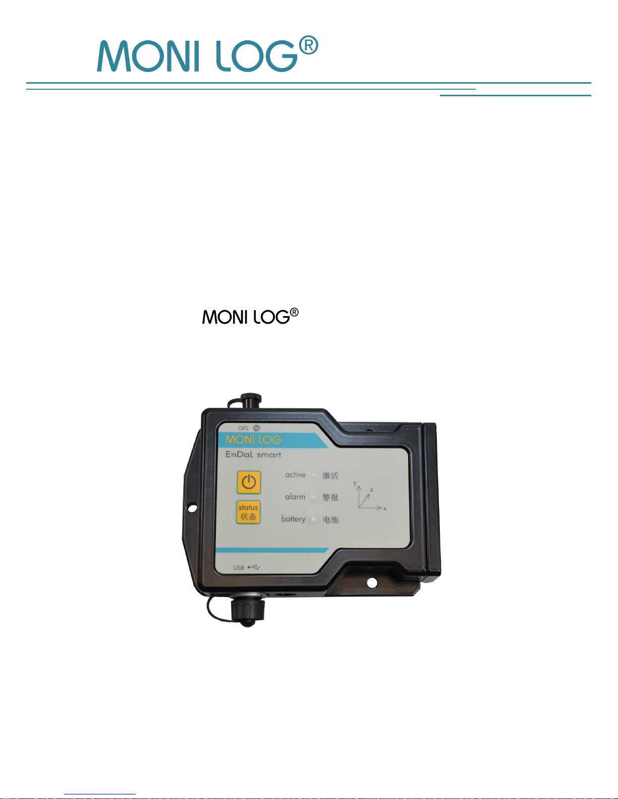
EnDaL smart
Edition 11/2015
INSTRUCTION MANUAL
for
EnDaL smart
(Transport data logger)


EnDaL smart PRODUCT CERTIFICATION
- 1 -
P R OD U CT C ERTI F ICATION
This device complies with part 15 of the FCC Rules. Operation is subject to the
following two conditions: (1) This device may not cause harmful interference, and
(2) this device must accept any interference received, including interference that
may cause undesired operation.
Modifications not expressly approved by this company could void the user's
authority to operate the equipment.
This equipment has been tested and found to comply with the limits for a Class A digital device,
pursuant to part 15 of the FCC Rules. These limits are designed to provide reasonable protection
against harmful interference when the equipment is operated in a commercial environment. This
equipment generates, uses, and can radiate radio frequency energy and, if not installed and used in
accordance with the instruction manual, may cause harmful interference to radio communications.
Operation of this equipment in a residential area is likely to cause harmful interference in which case
the user will be required to correct the interference at his own expense.
This device complies with Industry Canada’s RSS-310. Operation is subject to the
condition that this device must not cause harmful interference and must accept any
interference, including interference that may cause undesired operation of the
device.
Cet appareil est conforme à la norme RSS-310 d'Industrie Canada. L'opération est
soumise à la condition que ce dispositif ne doit pas causer d'interférence nuisible et
doit accepter toute interférence, y compris les interférences qui peuvent entraîner
un mauvais fonctionnement de l'appareil.
This EXPERTISE is issued in accordance with the Directive 1999/5/EC of the
European Parliament and Council on radio equipment and telecommunications
terminal equipment and mutual recognition of their conformity dated 9th March
1999 and is only valid in conjunction with following annex: -1- (2 pages)
This device has been designed to operate with the antennas listed below (see Technical Parameter). Antennas not
included in this list are strictly prohibited for use with this device. The required antenna impedance is 50
ohms.To reduce potential radio interference to other users, the antenna type and its gain should be so chosen
that the equivalent isotropically radiated power (e.i.r.p.) is not more than that permitted for successful
communication.
Cet appareil a été conçu pour fonctionner avec les antennes énumérées ci-dessous (voir 2. Paramètres techniques). Les
antennes n’étant pas énumérées dans cette liste sont strictement interdites pour une utilisation en combinaison
avec cet appareil. L'impédance de l’antenne requise est de 50 ohms. Afin de réduire les interférences radio
potentielles pour les autres utilisateurs, le type d'antenne doit être choisi afin que la puissance isotrope
équivalente (e.i.r.p.) ne soit pas supérieure à celle permise pour réaliser une communication stable.
TABLE OF CONTENTS EnDaL smart
- 2 -
T A B L E OF CONTENTS
PRODUCT CERTIFICATION .................................................................................. 1
TABLE OF CONTENTS ........................................................................................ 2
1. INTRODUCTION ...................................................................................... 4
1.1 SCOPE OF DELIVERY .................................................................................................... 4
1.2 FUNKTIONALITY ......................................................................................................... 5
1.3 ENVIRONMENTAL AND SAFETY INSTRUCTIONS ................................................................... 7
2. TECHNICAL PARAMETERS ......................................................................... 8
3. DEVICE DESCRIPTION OF ENDAL SMART .................................. 10
3.1 DEVICE SETUP / DEVICE VIEW ...................................................................................... 10
3.2 OPERATION OF THE
®
ENDAL SMART ............................................................... 11
3.3 MEANING OF THE LED STATUSES ................................................................................. 12
3.4 DEVICE RUNTIME AND BATTERY CHANGE ....................................................................... 15
3.5 MOUNTING INFORMATION ........................................................................................ 17
4. PC SOFTWARE – ANALYZER ................................................... 18
4.1 INSTALLATION ......................................................................................................... 18
4.1.1 General software installation ....................................................................................... 18
4.1.2 USB driver ................................................................................................................ 19
4.2 GENERAL USE OF THE PC SOFTWARE ........................................................................... 20
4.2.1 Establishing the device connection ................................................................................ 20
4.2.2 File area ................................................................................................................... 21
4.2.3 Message window (Log) ............................................................................................... 21
4.2.4 View of the measurement data ..................................................................................... 22
4.3 ENDAL SMART…. ................................................................................... 24
4 .3 . 1 Re a di n g o u t s ta t u s , co n fi g u r a t io n a n d m e as u re m e nt da t a ..................... 24
4.3.2 Overview window ...................................................................................................... 25
4.3.3 Status and thresholds .................................................................................................. 26
4.3.4 System events ............................................................................................................ 29
4.3.5 Logging periods ......................................................................................................... 30
4.3.6 Synchronous data graphs ............................................................................................ 31
4.3.7 Inclination curves ....................................................................................................... 33

EnDaL smart TABLE OF CONTENTS
- 3 -
4.3.8 Alarm events .............................................................................................................. 34
4.3.9 Shock events and shock curves ..................................................................................... 35
4.3.10 GPS position determination .......................................................................................... 38
4.3.11 Configuration of the EnDaL smart ................................................................ 42
INTRODUCTION EnDaL smart
- 4 -
1. I N T R OD U CTIO N
1.1 S C O P E O F D E L I V E R Y
Thank you
for having chosen the EnDaL smart.
Scope of delivery1 (standard):
EnDaL smart, incl. 2 x R14, alkaline or lithium batteries according to your
requirement
Installation CD
Configuration software „ Analyzer“ with integrated software help
Driver for USB interface
Operating instruction in electronic form (PDF)
Hard copy of the operating instruction
USB 2.0 interface cable (type A ↔ type Mini AB)
GPS antenna
In order to be able to further optimise our products for the respective applications, we are always
open to suggestions and change requests on your part.
1) The scope of delivery can deviate from the standard due to special contract agreements!

EnDaL smart INTRODUCTION
- 5 -
1.2 F U N K T I O N A L I T Y
The EnDaL smart is a universal data logger. Developed for long-term measurement
applications, it is perfectly suited for the monitoring of transport goods and critical environments.
The integrated sensor system for the detection of shock events and for the measurement of
temperature, humidity, air pressure, and inclination enables a wide range of different
measurement applications.
Configured alarm thresholds ensure the reliable detection of exceedances of limit values. The
possibility of position determination of the EnDaL smart at events and time-
controlled allows both the verification of the transport route and a precise localisation of critical
transport processes.
The up to 15,000 recorded position data sets,
including speed and direction, can be
imported afterwards into Google Earth or
similar software and be evaluated.
The compact and network-independent design enables
simple fixing on or in transport goods and transport devices.
The case of the device protects against dust and splash water
(degree of protection IP 65) and thus is also suitable for the
exterior use. Thanks to this, the EnDaL smart can be
universally used as an almost invisible goods companion in the
international transport of goods, in storage rooms, at reloading
points and during transport by rail, by roads as well as by water
and by air.
The power supply is realised by customary, exchangeable alkaline or lithium batteries. Thanks
to very low current consumption and associated very long, maintenance-free operating time, the
EnDaL smart is perfectly suited for self-sufficient long-term applications. Energy-
optimised operating settings render possible a self-sufficient operational time of up to one year
under rough ambient conditions.

INTRODUCTION EnDaL smart
- 6 -
The licence-free configuration software Analyzer enables a simple and intuitive
configuration of the devices. It offers a comprehensive adjustment of the device functions to your
application-specific requirements. Besides the detailed evaluation of the device data in measured
value tables and graphs, the programme also provides export functions for external applications
(e.g. Microsoft Excel).
EnDaL smart INTRODUCTION
- 7 -
1.3 E N V I R O N M E N T A L A ND S A F E T Y INS T R U C T I O N S
Environment & disposal
The EnDaL smart contains, excluding the internal batteries, no corrosive or
environmentally damaging substances.
Used batteries must be immediately removed from the device and be disposed of in an
environmentally friendly manner, according to the applicable legislation. Lithium batteries are
hazardous waste.
Battery operation
The power supply is ensured in the EnDaL smart by means of 2 exchangeable
alkaline or lithium batteries (type C|R14). These can be bought in specialized stores according to
the specification stated in the instruction manual.
When lithium batteries are used on transport, the EnDaL smart must be labelled as
hazardous material of class 9, according to the Worldwide UN classification. The transport
conditions resulting due to this must be taken into account!
Please take into account that when using alternative battery types the functionality of the device
cannot be guaranteed in the entire specified temperature range from -40 to 85 °C.
ATTENTION!
Use only intrinsically safe batteries.
In case of non-compliance with the national regulations/laws applicable in the handling of
lithium batteries, any liability and warranty claim becomes void!
Decommissioning
In case of decommissioning the devices must be properly switched off and all batteries must be
removed from the cases and be disposed of in an environmentally friendly manner.
TECHNICAL PARAMETERS EnDaL smart
- 8 -
2. T E C HN IC AL PAR AM E TER S
Case
Case material
Aluminium, powder-coated
Degree of protection
IP67
Weight
0.8 kg (standard version without batteries)
38g (each magnetic base, 3 pieces per module optional)
Dimensions (H/W/D)
35 x 140 x 100 mm³ (standard version)
Ø25mm x 15mm (small magnetic base)
Mounting type
surface mounting (screw fixing recommended), alternatively magnetic base
mounting (upon request)
Application conditions
Operating and storage
conditions
-20°C to +70°C with alkaline batteries
-40°C to +85°C with Lithium batteries
Data memory, time
Data retention
minimum 10 years (independent of battery condition)
Memory type/size
32 MB flash parameter and data memory
System time
Date / Time as UTC time supported independently from the power
supply by an internal battery,
exchange at SMT & HYBRID after 6 years needed
Voltage supply
Internal
2 batteries of type C or R14 exchangeable
o alkaline batteries (2 x 1.5 V; 8000 mAh)
o Lithium batteries exchangeable (2 x 3.6 V; 8500 mAh)
Service life: at least 1 year (in case of synchronous interval of 10 min,
all options active)
External interfaces
USB
USB 2.0 Client (Mini-USB AB)
Indicating and operating elements
LED
1 green active LED
1 red alarm LED
1 red-green battery LED (bicoloured)
Key button
1 On/Off key
EnDaL smart TECHNICAL PARAMETERS
- 9 -
1 status key
Position determination
Channels
32 satellites (GPS, SBAS, BeiDou, QZSS)
Antenna
SMA socket for the connection of an external active antenna 50 Ω (3-30 mA
/ 3 V / rod or cable antenna)
Tested GPS antenna
Type
Chinmore GS-10DSMA3V-002 (magnetic antenna with cable,
SMA plug)
Amplification/ Impedance
30 dBi / 50 Ω
Device approval
CE, IC, FCC
Device sensors
Measuring quantity
Measuring range
Tolerance
acceleration/shock
+/- 16 g (3 axes)
Upon exceedance of a recording
threshold, a shock curve (2kHz, 1sec)
is recorded. The 500 largest shock
curves are saved.
(optional: 100g/400g; 1kHz)
+/- 50 mg
(+/- 200 mg)
Temperature
-40 °C – 85 °C
+/- 0.3 °C
Relative air humidity
0 % - 100 %
+/- 2 %
Air pressure
260 – 1260 mbar
(optional: 10 – 2000 mbar)
+/- 2 mbar
(+/- 4 mbar)
Inclination
Inclination calculation from static
acceleration
Upon exceedance of an inclination
threshold, an inclination curve (12 Hz,
8 sec) is recorded. Up to 640
inclination curves are saved.
+/- 5 degrees
DEVICE DESCRIPTION OF MONI LOG® ENDAL SMART EnDaL smart
- 10 -
3. D E VI C E D ESCRIPTION O F
E n d aL smart
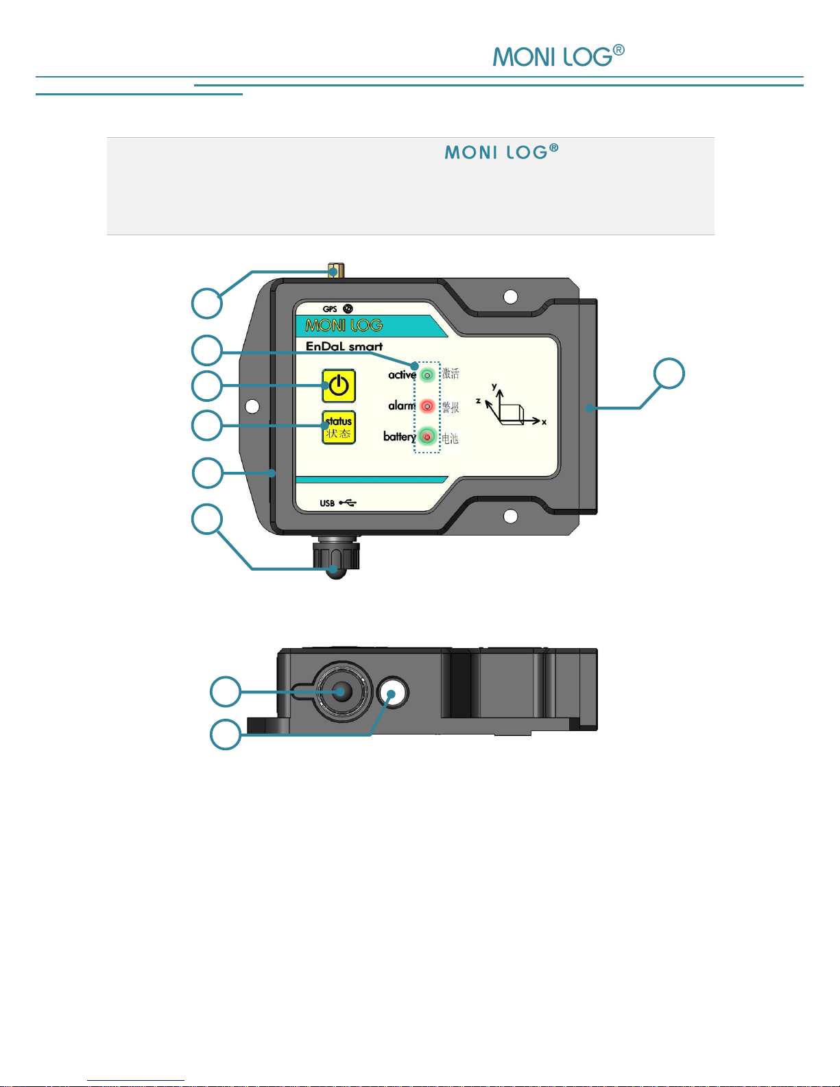
3.1 D E V I C E S E T U P / D E V I C E V I E W
Top view:
Front view:
1 Battery cover
5 status key
2 connector for GPS antenna
6 Name plate
3 Status and activity LEDs
7 USB port
4 On/Off key
8 Temperature/humidity sensor
1
2
8
7
6 3 7
4
5
EnDaL smart DEVICE DESCRIPTION OF MONI LOG® ENDAL SMART
- 11 -
3.2 O P E R A T I O N O F T H E
®
E n D a L s m a r t
For the operation of the device, there is an “On/Off” key and a “status” key. The “On/Off” key
serves to activate and to deactivate the device. The “status” key serves to request a simple visual
status output. For the visualisation of the possible statuses, there are 3 LEDs available at the
device.
Checking the on-state of the device
In order to determine whether the EnDaL smart is switched on or off, briefly press
the On/Off key:
Green active-LED does not light up the device is OFF
Green active-LED briefly lights up the device is ON
Switching on the device
To switch on the EnDaL smart, press the On/Off key (~1 second) until the green LED lights up.
After that, release the key. Subsequently, the device starts recording data.
If the device is provided with a switch-on/switch-off code, it can only be activated via the
software. In order to signalise this, the active LED and the alarm-LED begin to flash when the
On/Off key is pressed for a longer time (~1 second). If no activation is carried out via the
software, the device switches of again after 20 seconds. In order to activate the device, connect it
to a PC while the active and the alarm-LEDs are flashing, and start the Analyzer.
When reading out the device, it is recognised that the device is password-protected. At this point
you are requested to enter the device password. Follow the instructions of the software in order to
switch on the device.
Explanations for the configuration of the switch-on/switch-off code can be found in chapter
4.3.11 in the paragraph „Password configuration“
Switching off the device
To switch off the EnDaL smart, keep the On/Off key pressed. After a short time, the red alarmLED will start to flash. If you continue to keep it pressed, it will light permanently. Now it can be
released. Then the device switches off. This can be verified by briefly pressing the On/Off key or
the status key.
If the On/Off key is released while the alarm-LED is flashing, the device remains switched on.
DEVICE DESCRIPTION OF MONI LOG® ENDAL SMART EnDaL smart
- 12 -
If the device is provided with a switch-on/switch-off code, it can only be deactivated via the
software. In order to signalise this, the active-LED begins to light up and the alarm-LED begins to
flash when the On/Off key is pressed for a longer time (~1 second). In order to switch off the
device, connect it to a PC and start the Analyzer. When reading out the device, it is
recognised that the device is password-protected. At this point you are requested to enter the
device password. Via the tab “Configuration” and the button “Code word configuration”, you
can switch off the device now.
Explanations for the configuration of the switch-on/switch-off code can be found in chapter
4.3.11 in the paragraph „Password configuration“
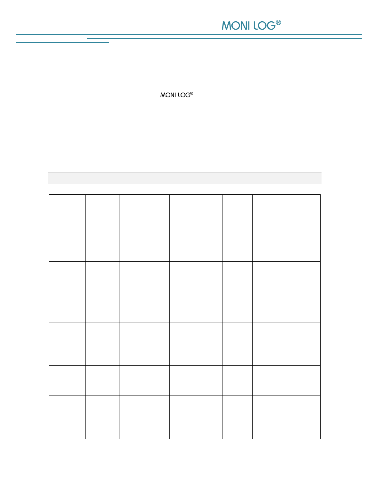
3.3 M E A N I N G O F T H E LED S T A T U S E S
LED
What?
How?
When?
2nd
L
E
D
?
Meaning
Green
(active)
illuminated
~ 1 second
switching on
-
device switched on
Green
(active) &
Red
(alarm)
flashing
max. 20 seconds
switching on
Green
& Red
a switch-on password
via software is expected
Green
(active)
illuminated
1x flashing
briefly
key pressed
briefly
-
device is active
Green
(active)
illuminated
~ 1 second
USB active
-
USB
connected/disconnected
Green
(active)
flashing
irregularly
USB active
-
USB data transmission
Green
(active)
illuminated
0.1 - 8 seconds
device active
-
recording of
shock, synchronous or
event data
Green
(active)
flashing
regularly
device active
searching for
GPS coordinates
Green &
Red
illuminated
4 seconds
permanently
USB configuration
Green
& Red
memory is deleted

EnDaL smart DEVICE DESCRIPTION OF MONI LOG® ENDAL SMART
- 13 -
LED
What?
How?
When?
2nd
L
E
D
?
Meaning
Red
(alarm)
flashing
3x briefly
On/Off key
pressed longer
than 2s
-
device prepares
deactivation
Red
(alarm)
illuminated
while key is
pressed
On/Off key
pressed longer
than 3s
-
device switches off
(LED goes out when key
is released)
Red
(alarm)
flashing
up to 3x briefly
On/Off key
pressed longer
than 2s and
then released
Green
flashes
briefly
device remains
switched on
Red
(alarm)
flashing
3x briefly, 3x
long, 3x briefly
(SOS)
switching on
Green
Hardware error in the
memory
Red
(alarm)
flashing
3x briefly, 3x
long, 3x briefly
(SOS)
switching on
-
Battery empty, device
switches off again
Red
(alarm)
flashing
5x briefly
switching on
or USB
configuration
Green
main position could not
be determined
inclination event
inactive
Red
(alarm)
flashing
sustained at
1 Hz
switching on
-
Update mode active or
no valid firmware found
Green
(active)
illuminated
while pressed
status key
pressed
others
possible
device is active and
records data
Green
(active)
not
illuminated
while pressed
status key
pressed
others
possible
device is inactive, it is
before the time of
activation or after the
time of deactivation
(no data are recorded)
Green
(active)
while pressed
status key
pressed
others
possible

DEVICE DESCRIPTION OF MONI LOG® ENDAL SMART EnDaL smart
- 14 -
LED
What?
How?
When?
2nd
L
E
D
?
Meaning
Red (alarm)
illuminated
while pressed
status key
pressed
others
possible
An alarm value has
been exceeded
Red (alarm)
not
illuminated
while pressed
status key
pressed
others
possible
No alarm values has
been exceeded yet
Green
(battery)
illuminated
while pressed
status key
pressed
others
possible
The battery still has a
residual charge of
more than 50%
Orange
(battery)
illuminated
while pressed
status key
pressed
others
possible
The battery has a
residual charge
between
50% and 25%
Red
(battery)
illuminated
while pressed
status key
pressed
others
possible
The battery has a
residual charge
between
25% and 10%
Red
(battery)
flashing
while pressed
status key
pressed
others
possible
The battery has a
residual charge of less
than 10%

EnDaL smart DEVICE DESCRIPTION OF MONI LOG® ENDAL SMART
- 15 -
3.4 D E V I C E R U N T I M E A ND B A T T E R Y C H A N G E
Device runtime
The device runtime of the EnDaL smart depends on the set measurement parameters.
Here, the interval setting of the GPS position determination is the key factor. The connection
between device runtime and GPS or synchronous interval is illustrated in the following figure:
Figure 1: Estimation of the device runtime in dependence on the synchronous interval
0
100
200
300
400
500
600
1 10 100 1000
runtime [days]
Synchronous interval[min]
Use with internal GPS-receiver Use with inclination measurement Use without any syncronous measurement

DEVICE DESCRIPTION OF MONI LOG® ENDAL SMART EnDaL smart
- 16 -
Battery change
Prior to the battery change, the EnDaL smart must be properly switched off.
Otherwise a data loss of the device cannot be excluded.
Attention:
Ensure the right polarity when inserting the batteries!
For the change of the batteries proceed as follows:
1) Remove the battery cover by loosening the fastening screws by means of a screw driver (cross
recess, H size2).
Remove the battery bridge by loosening the fastening screws by means of a screw driver
(hexagon socket, size 2.5 mm). Afterwards, you can simply remove the batteries.
2) Now insert the new battery according to the specified polarity into the device.
3) In a last step, screw in tight again the battery bridge and the battery cover. Please take into
account the maximum tightening torque of 0.5 Nm.

EnDaL smart DEVICE DESCRIPTION OF MONI LOG® ENDAL SMART
- 17 -
3.5 MOUNT I N G I N F O R M A T I O N
The device can be attached by means of 3 fastening screws (see Figure 2) on the transported
goods, according to the marked mounting holes. Optionally, the device can also be mounted on
magnetic surfaces with the aid of magnetic bases.
For the mounting of the GPS antenna of the EnDaL it must be taken into account that
a clear view from the mounting location to the sky considerably improves the GPS reception
conditions. An enclosure or covering of the GPS antenna may considerably deteriorate the GPS
reception or even completely prevent it. A poor GPS reception may lead to an increased current
consumption and thus to a shortened device runtime.
Figure 2: Dimensions and mounting information of the EnDaL smart
Mounting holes

PC SOFTWARE – MONI LOG® ANALYZER EnDaL smart
- 18 -
4. PC S O F TW ARE – A N A L Y Z E R
The software Analyzer can be used both for the readout and configuration of the
EnDaL smart and other devices. It is intended for the display and analysis
of the recorded data in tabular and graphic form. Furthermore, data sets can be saved locally on
your PC or loaded from your PC.
4.1 I N S T A L L A T I O N
4 . 1 . 1 G e n e r a l s o f t w a r e i n s t a l l a t i o n
The supplied CD contains the installation of the Software Analyzer. Please start the
installation by double-clicking on the file „setup.exe“, and follow the instructions.
Together with the installation of the evaluation software Analyzer, the required USB
device drive is installed. If the installation of the USB driver was not successful, the driver can be
installed manually. Please refer to chapter 4.1.2 .

EnDaL smart PC SOFTWARE – MONI LOG® ANALYZER
- 19 -
4 . 1 . 2 U S B d r i v e r
Note:
If there are problems with the installation of Analyzer, it may be necessary to install
the driver for the USB connection manually.
For the installation of the USB driver, the following points must be observed:
You need administrator rights to update a driver.
The figures may differentiate from the view of your device manager.
There may be a differentiating system language.
The driver must be set only once on your computer in case of a successful installation.
Installation process
1. Connect the EnDaL smart by means of the included USB cable to your PC.
When connecting the device, the green active-LED lights up. After the LED has gone out,
the USB device is ready.
2. Open the folder of the included CD and execute the file “USB-driver-install.exe” as
administrator. (via right-click)
3. Follow the instructions until the installation is finished. Subsequently, you can read out the
EnDaL smart using the software Analyzer.

PC SOFTWARE – MONI LOG® ANALYZER EnDaL smart
- 20 -
4.2 G E N E R A L U S E O F T H E PC S O F T W A R E
4 . 2 . 1 E s t a b l i s h i n g t h e d e v i c e c o n n e c t i o n
When the device driver is installed and a device is connected via USB, the connection will be
established automatically as a rule upon start of the evaluation software.
If the evaluation programme has already been active before plugging the device, move the mouse
in the area [COM-Port] (Figure 3). The connection is established automatically. If you would like
to connect a device at another COM-Port, click onto the USB symbol and select it in the selection
window (see for this Figure 4).
Figure 3: No connection select COM-Port
Figure 4: USB connection window: currently connected to COM15
COM16 also available
In case of connection problems:
If no connection can be established to the device, select the
Refresh button (blue double arrow) and disconnect the USB cable from the
device. Afterwards, reconnect it with the USB cable.

EnDaL smart PC SOFTWARE – MONI LOG® ANALYZER
- 21 -
4 . 2 . 2 F i l e a r e a
Data that are read out from a device can be saved as file. A click on the button
“Save file” opens the corresponding dialogue. A click on the button with the Excel symbol exports
the read-out files into an Excel file.
Figure 5: File area
Likewise, saved data can be fed again into the PC programme. The button “Load file” opens the
corresponding dialogue for the selection of the desired file.
4 . 2 . 3 M e s s a g e w i n d o w ( L o g )
The message window, which can be found as a programme tab “Log”, renders possible an
overview on the actions performed by means of the programme or the status changes of the
device during the established USB connection. Error messages and notes, e.g. for executing
configuration commands, connection establishment to devices, saving of data etc. are listed here.
Figure 6: Log-window

PC SOFTWARE – MONI LOG® ANALYZER EnDaL smart
- 22 -
4 . 2 . 4 V i e w o f t h e m e a s u r e m e n t d a t a
Graphs
In a graph it is possible to zoom in. For this purpose, draw up a selection window using the
mouse (see Figure 7). The view of linear represented graphs can be shifted using the held right
mouse button . Logarithmically represented graphs can be zoomed at the desired place, but
cannot be moved. By moving the mouse wheel up/down, concentric zooming is carried out. The
standard zoom is restored by double-clicking on the graph, or using the button .
Figure 7: Zoom-selection window

EnDaL smart PC SOFTWARE – MONI LOG® ANALYZER
- 23 -
Sorting function in tables
For tables a sorting function is available. This is carried out by clicking on the respective column
in the table header. This facilitates the finding of the maximum/minimum values. The sorting is
made alternatingly in ascending and descending order. The data sets remain unchanged by this.
Figure 8: Sorting the table columns

PC SOFTWARE – MONI LOG® ANALYZER EnDaL smart
- 24 -
4.3 E n D a L s m a r t ….
4.3 .1 R ea d ing ou t st atu s, c on f ig u rat ion an d me asu r em e nt
dat a
After the connection to the EnDaL smart is successfully established, the following information is
shown in the PC programme:
Figure 9: Programme view during connection with EnDaL smart
1) Status data EnDaL smart
2) set configuration parameters
After the connection to the device is established, the status data, configuration and acquisition
periods are read out automatically. The measurement data, such as synchronous data or shock
curves, are retrieved manually via the button „Read out EnDaL smart“. This can take up,
depending on the number of the data sets, a few seconds to several minutes.
A progress bar shows the current readout status. According to the available measured values the
corresponding programme tabs and graphs open. According to the available measured values
the corresponding programme tabs and graphs open.
A detailed description of the programme areas can be found in the following chapters.
1
2

EnDaL smart PC SOFTWARE – MONI LOG® ANALYZER
- 25 -
Please do not disconnect the USB cable from your PC or EnDaL smart, as long as the data
transmission takes place!
4 . 3 . 2 O v e r v i e w w i n d o w
The overview shows the current system time, the set synchronous interval and the number of the
saved data sets (see Figure 10).
Figure 10: Overview window of the EnDaL smart
Moreover, the following functions are available in the overview window:
1) Reading out the measurement and diagnostic data
The retrieval of all recorded measured values and diagnostic data is made by clicking on
the button “Reading out EnDaL smart”. According to the available measured values the
corresponding programme and diagram tabs open.
2) Defining the view period
By means of the view period (see Figure 10, no. 2), the display of data can be limited to
the desired time range. This facilitates the data analysis and the finding of certain events.
Enter the desired start and end date in the fields and confirm the entry with the aid of the
Enter key of your keyboard or by means of the green button to the right of the input fields.
1
2

PC SOFTWARE – MONI LOG® ANALYZER EnDaL smart
- 26 -
Furthermore, the view period can be adjusted via the slide bar; by moving the blue bars
with the mouse (see Figure 11).
Figure 11: Slide bar for view period
4 . 3 . 3 S t a t u s a n d t h r e s h o l d s
Figure 12: Status and set configuration of a sensor module
Status data:
Intervals: number of synchronous records
logging periods: number of the started active periods
System events: number of the recorded events for the extended diagnosis
Alarm events: number of the events with exceedance of alarm thresholds (shock,
inclination, temperature, humidity or/and pressure)
Inclination curves: number of the inclination curves due to the exceedance of threshold
for inclination events
Shock events: recorded shock curves due to the exceedance of the recording
threshold for shock events

EnDaL smart PC SOFTWARE – MONI LOG® ANALYZER
- 27 -
Shock release counter: number of the releases by the release threshold of the
device. Shocks that will not reach the set recording thresholds
(shock magnitude, shock strength and shock duration) are rejected
again. Thus, this value is purely informative and signalises that
events have been detected by the device.
Device name: device designation by the user (freely selectable)
Notes field: field for programming a note in the device (mailbox)
Serial number: serial number of the device (unchangeable)
Start of recording: beginning of the measurement recording by user or by measurement
programme
Stop of recording: end of the measurement recording by user or by measurement
programme
Synchronous interval: set interval, at which synchronous data are recorded (temperature,
humidity, pressure, inclination, GPS).
System time: current time at the PC, with which the device had been read out.
Commissioning: date and time of the first commissioning
Operating hours: total operating time of the device since commissioning at the
manufacturer
Battery voltage: voltage of the device battery
Battery level: current percentage battery reserve (estimated device runtime in
hours)
Zero position inclination: spatial position of the device when the recording starts
GPS tracking: set interval, for the determination of the current GPS position
Last GPS position: last determined GPS position with deposited link to Google Maps
GPS points: number of the successfully determined GPS position data
Firmware version: current firmware version of the device
Hardware version: current Hardware version of the device

PC SOFTWARE – MONI LOG® ANALYZER EnDaL smart
- 28 -
Shock event thresholds:
Release threshold: acceleration value, above which the scanning is activated
Recording threshold shock magnitude: minimal amplitude of the acceleration
(storage criterion)
Recording threshold shock strength: minimal „area below the curve“ (storage criterion)
Recording threshold shock duration: minimal duration of the event (storage criterion)
Shock alarm threshold: acceleration value, above which an alarm event is created
Memory criterion: The shock event must reach at least the stated values to
befit for memory. This serves to hide the insignificantly
small shock events and in this way not to load excessively
memory and transmission path (Bluetooth & E-Mail).
Filled circle • : event active
Non-filled circle º : event not active
Event/alarm thresholds:
Temperature upper/lower: Upon exceedance/falling below, an event is created
Humidity upper/lower: Upon exceedance/falling below, an event is created
Inclination/inclination curve: If the device tilts from its zero position by the stated angle
(e.g. 30°), an event is created.
Inclination curves record the course of the tilting over a
period of some seconds.
Pressure upper/lower: Upon exceedance/falling below of the values, an event is
created
Notes on inclination events:
As the inclination is naturally superimposed with other movements and put under
general scatterings, the minimum threshold is limited to an angle of 5°. The scanning
is carried out with 12 Hz during a timeframe of 3 seconds; i.e., a faster tilting cannot
be detected under certain circumstances.
EnDaL smart PC SOFTWARE – MONI LOG® ANALYZER
- 29 -
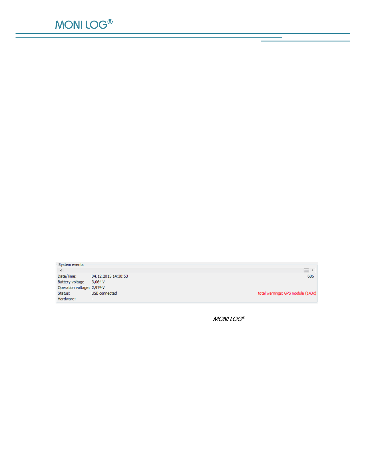
4 . 3 . 4 S y s t e m e v e n t s
The system events show events that concern the status and the operating behaviour of the device.
Possible errors in the hardware are also recorded. The display field for system events is normally
hidden and can be shown by activating the option “Extended diagnosis” in the menu „Settings“.
The following system events can occur:
Turned on: the device had been switched on
Hour counter: 24 h of operating time of the device are expired
Device configured: the device had been configured.
Thresholds configured: alarm events/thresholds were activated/changed
Turned off: the device had been switched off
Time synchronised: the system time of the device had been configured
USB (dis)connected: the event was caused by activities via the USB interface
GPS active: device searches GPS-coordinates
Hardware inactive: parts of the device had been deactivated
Failure: an internal error occurred please contact the manufacturer
Figure 13: Display of the system events of a EnDaL smart

PC SOFTWARE – MONI LOG® ANALYZER EnDaL smart
- 30 -
4 . 3 . 5 L o g g i n g p e r i o d s
The logging periods offer an overview on the individual configuration time segments of the
EnDaL smart. In this way, it can be traced back how the device was configured at the
respective period of time.
Figure 14: Table with logging periods
The start and end time, the active time period and the reason which has led to the completion of
the logging period are shown. Moreover, all set thresholds and event channels for the period are
recorded. A new logging period begins, when the device had been switched off or configured.

EnDaL smart PC SOFTWARE – MONI LOG® ANALYZER
- 31 -
4 . 3 . 6 S y n c h r o n o u s d a t a g r a p h s
Synchronous values - temperature, humidity, inclination & air pressure:
The up to 200,000 data sets of the synchronous values are shown consecutively in a table (see
Figure 15). In the programme tab “Synchronous values graph” the synchronous data are shown
as a graph. By activating or deactivating the “check marks” in the legend on the right side, the
graphs for the quantities temperature, air humidity, air pressure and inclination can be switched
on or off (see Figure 16).
Figure 15: View of synchronous data table
Figure 16: View of synchronous data graph

PC SOFTWARE – MONI LOG® ANALYZER EnDaL smart
- 32 -
Inclination graph:
In the programme tab “Inclination position graph”, the static inclination values of the synchronous
dates are shown as a graph. By activating or deactivating the “check marks” in the legend on the
right side, the x-, y- and z-channel can be switched on or off respectively (see Figure 17). The
static inclination can be superimposed by occurring accelerations. The representable area is at
± 2 g. For that purpose, check the magnitude: if it significantly deviates from 1 g, then the actual
position is no longer reliably determinable.
Figure 17: View of inclination position graph
Inclination angle:
The human imagination quickly reaches its limits in case of a three-dimensional representation of
the spatial position of three coloured lines. For the better understanding of the orientation of the
sensor module, use is made of the graphical representation of the three spatial angles in the style
of analogous aircraft instruments. The designations are based upon the ENU reference system
(“right hand rule“, see https://en.wikipedia.org/wiki/Aircraft_principal_axes).
Calculation of the angles:
Rotation around x-axis: roll angle Φ = arctan (y/z)
Rotation around y-axis: pitch angle Θ = arctan (z/x)
Rotation around z-axis: yaw angle Ψ = arctan (x/y)

EnDaL smart PC SOFTWARE – MONI LOG® ANALYZER
- 33 -
By this definition the angles in the normal position of the device on the table are not (0°,0°,0°),
but (0°,90°,--). The roll angle is 0°, since the z-axis shows in the direction of the axis of the Earth.
The pitch angle is 90°, since the x-axis is standing vertically to the axis of the Earth (namely
horizontal). The yaw angle (rotation around the z-axis) cannot be determined, since the
gravitational acceleration for both reference axes (x- & y-axis) is almost zero.
Figure 18: Example of inclination angle display
4 . 3 . 7 I n c l i n a t i o n c u r v e s
Inclination curves record the inclination for further 8 seconds as course of the curve after an
inclination event.
Inclination events often superimpose with acceleration events in reality. Check in case of
inclination curves, if the magnitude has a course of approximatively 1 g. If this is the case, this is
a “gentle tilting” without jerky movements (see Figure 19). In the other case, a “vibration” or a
similar jerky process has triggered the inclination event.
For inclination curves, also the angular display is available.

PC SOFTWARE – MONI LOG® ANALYZER EnDaL smart
- 34 -
Figure 19: Inclination curves graph
4 . 3 . 8 A l a r m e v e n t s
Alarm events comprise all events created by exceeding/falling below alarm thresholds. IN the
EnDaL smart, up to 29,000 alarm events can be stored. They are listed in the
programme tab “alarm events” as single tables (pressure events, temperature/humidity events,
inclination events/inclination curves, and shock alarm events). With the corresponding
configuration, a GPS coordinate point is created for every event. The number of the event is
additionally specified in brackets in the data table.
Figure 20: Inclination event table and inclination curves graph

EnDaL smart PC SOFTWARE – MONI LOG® ANALYZER
- 35 -
4 . 3 . 9 S h o c k e v e n t s a n d s h o c k c u r v e s
All shock events are set out in tabular form under the programme tab “Shock events“. By a double
click on the table row, the corresponding curve can be accessed.
Figure 21: Shock event table
In the programme tab “Shock curves graph” the recorded shock curves are shown as a graph. By
activating or deactivating the “check marks” in the legend on the right side, the x,y,z-
the magnitude curve can be shown or hidden respectively (see
Figure 22)
In addition, by activating the low-pass filter function and input of the critical frequency, the
unwanted high frequency portions can be filtered out from the view. This is a view option and it
does not change the original data.
By means of the button “Display range: ± 16 g”, the vertical graph axis is switched between the
limits of the curve and ± 16 g.

PC SOFTWARE – MONI LOG® ANALYZER EnDaL smart
- 36 -
Figure 22: Shock curves graph
Shock recording:
The shock recording begins, when the value of the acceleration exceeds the triggering threshold.
The triggering threshold is configured internally by the device and depends on the set magnitude
threshold (triggering threshold = ½*magnitude threshold, minimum: 500 mg). This way,
processes which lie chronologically before the actual exceeding of the magnitude threshold are
also registered.
A shock event is saved if the recording thresholds for shock magnitude, shock strength and
shock duration are at least fulfilled.
Figure 23: Criteria for the shock recording
The largest single pulse within the scanning time of 1024 ms is considered as a shock event,
which meets all set conditions (shock magnitude, shock strength, shock duration). A single pulse is
deemed to be completed, if all three channels (x,y,z) are below 200 mg according to magnitude
for more than 100 ms (fading condition). The shock pulses are compared with each other
regarding their shock strength (corresponds to time integral over the course of the shock
magnitude).
The following should be explained on the basis of Figure 24. The 1st pulse begins with the start of
the recording and fades away again very quickly here. The following 2nd pulse begins with the
repeated exceeding of the triggering threshold (1). At point (2), all channels fall below the
200mg limit, however, not longer than 100 ms (3). At point (4), the fading condition is finally
fulfilled and the 2nd pulse is completed. More than 200 milliseconds after that, the 3rd pulse is
Magnitude r exceeds the
magnitude threshold (3 g)
Channel exceeds the
triggering threshold (1.5
Start of recording

EnDaL smart PC SOFTWARE – MONI LOG® ANALYZER
- 37 -
finally detected. Though the 3rd pulse shows the highest maximum amplitude, the 2nd pulse is the
greatest with respect to the shock strength and is used here for the shock evaluation.
Figure 24: Shock curve with 3 single pulses
Area: ± 200 mg
1.
2.
3.
Triggering threshold
> 100 ms
> 200 ms
432
1
y
z
x
magnitude
x-axis
y-axis
z-axis
Figure 25: EnDaL smart main axes for acceleration/inclination

PC SOFTWARE – MONI LOG® ANALYZER EnDaL smart
- 38 -
4 . 3 . 1 0 G P S p o s i t i o n d e t e r m i n a t i o n
The EnDaL smart offers the possibility to determine the current GPS position in
definable intervals (tracking function), during the recording of synchronous data, and during the
detection of shock and alarm events.
Configuration of the GPS tracking
The GPS tracking interval can be defined in the field “GPS tracking” (see Figure 26). If no GPS
tracking should be carried out, then no event channel has to be activated or the interval has to be
set to “0 h“ and “0 min“.
Note:
The configuration of the intervals for the position determination has a substantial influence on the
device runtime! Please see chapter 3.4 in this regard.
Figure 26: Configuration of the GPS tracking
Furthermore, one can adjust here at what time or event GPS coordinates shall be searched. Here
one can choose between the general shock event (all recording thresholds exceeded), alarm
events (shock, temperature, humidity, inclination, pressure), a synchronous recording and a GPS
tracking interval.

EnDaL smart PC SOFTWARE – MONI LOG® ANALYZER
- 39 -
Export and representation of the GPS recording in Google Earth
The recorded GPS data can be viewed with the aid of Google-Earth. In order to create a
corresponding route coordinates file, click in the menu tab “Status” on the button “GPS” (see
Figure 27). The number indicated in brackets corresponds to the number of the recorded GPS
data sets.
Figure 27: Reading out the recorded GPS data
The notification window that opens up subsequently (see Figure 28) allows to additionally save
the created position data in the selected format in any directory by clicking on „Ja“ (Yes). By
clicking on „Nein“ (No), no the file will not be saved additionally.
Figure 28: Additional saving of the created .gpx or .kml-file to a
user-defined memory location.

PC SOFTWARE – MONI LOG® ANALYZER EnDaL smart
- 40 -
If Google-Earth is installed on your PC, Google-Earth will be started now automatically. The
Figure 29 shows an example view of the GPS data in Google-Earth.
Figure 29: Representation of GPS data in Google Earth
The symbols displayed on the map show:
Beginning of route
Tracking point
End of route
Direction of motion
(starting from 3.0 km/h)
Alarm event
Stop position
Shock event

EnDaL smart PC SOFTWARE – MONI LOG® ANALYZER
- 41 -
A Click on one of the symbols opens a field with additional information of the GPS point
(see Figure 30)
Figure 30: Exemplary representation of the information fields of the GPS points

PC SOFTWARE – MONI LOG® ANALYZER EnDaL smart
- 42 -
4 . 3 . 1 1 Configuration o f t h e E n D a L s m a r t
Changing the device name
The name of the device can be changed in the programme tab “Configuration” in the input field
“Device name” (see Figure 31). Up to 16 characters are available for the device name. By
pressing the Enter key of your keyboard or by clicking on the configuration button the new
device name is transferred.
Figure 31: Changing the device name
Setting the recording period:
The desired recording period for the device can likewise be set by the user (see Figure 32). When
a recording period is defined, the measured value recording at the start time begins. The
measured value recording will be terminated when the stop time is exceeded. If the input fields
are not left empty, the measurement recording is running a long as the device is switched on.
The input of start time and stop time is made in local time in the date format:
dd.mm.yyyy hh:mm:ss
(day.month.year hour:minute:second)
The recording period is configured by pressing the Enter key on your keyboard or by clicking on
the button „Transferring the configuration “.
Figure 32: Configuration of the recording period

EnDaL smart PC SOFTWARE – MONI LOG® ANALYZER
- 43 -
Setting the device time
The device time can be set by clicking on the clock symbol in the programme tab
“Configuration” (see Figure 33). The synchronisation is made by means of the system time of
your PC.
All time specifications are made in the PC programme according to the
time zone setting of your PC. Internally, the device works with the Universal Time Coordinated
(UTC). Thus, a clear temporal assignment of the events with a point in time is always possible.
Figure 33: Setting the device time
During the operation, the device time is always synchronised per GPS, when the GPS position is
determined by the activity of the GPS tracking, the synchronous recording or as events of the
device occur.
PC SOFTWARE – MONI LOG® ANALYZER EnDaL smart
- 44 -
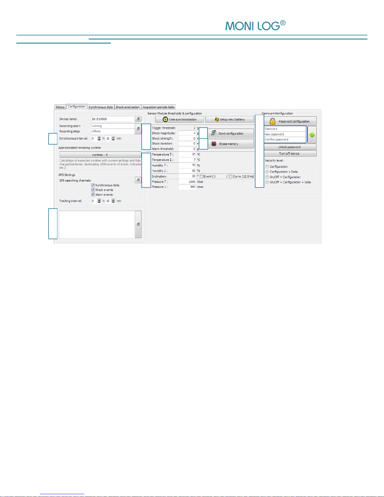
Configuration of the measurement parameters
The configuration area will only be visible, when a device is connected that you can configure.
When viewing data sets from files, this window is not displayed (Figure 34).
Figure 34: Measurement data configuration area EnDaL smart
1) Synchronous interval: Time between the synchronous recording of
measurement data (temperature, humidity, pressure,
inclination and GPS)
2) Text field: Text that is saved in the device concerning the
transport (e.g. order number, destination, client,
supplier, owner)
3) Configuration for shock measurement
4) Configuration for alarm events
5) Transferring the configuration: Sends all currently made settings
to the sensor module
6) Deleting the memory: Deletes all data in the memory of the sensor module
7) Configure password: Enables the modification, the configuration and the
resetting of the device password, as well as a
shutdown of the device via software
1
2
3
4
5
6
6

EnDaL smart PC SOFTWARE – MONI LOG® ANALYZER
- 45 -
Note:
Please refer to the description in chapter 4.3.3 „Status and thresholds“
for the meaning of the individual setting fields.
Changing the synchronous interval & setting of alarm events:
The setting of the synchronous interval is made with the aid of the selection fields (Figure 34,
no. 1) “Synchronous interval” (in hours + minutes).
The input fields below (Figure 34, no. 2 u. 3) allow to parametrise the alarm events. By means of
the adjusted threshold values (partially, lower and upper threshold values are adjustable) alarm
events are saved, if an exceedance of or a falling below the threshold values is detected during
the measurement run. An activated “check marks” in front of the input fields activates the creation
of the alarm events. If alarm events have occurred, this is shown when actuating the status key
above the alarm-LED.
The settings are saved by clicking on “Transferring the configuration” (Figure 34, no. 4) and are
transferred to the device.
Deleting the memory:
The function “Deleting the memory” (see Figure 34, no. 5) deletes all data that are stored in the
EnDaL smart.
Attention!
Make sure that you have read out the data completely and that you have saved them
as *.esm-file before deleting them! Deleted data cannot be recovered!

PC SOFTWARE – MONI LOG® ANALYZER EnDaL smart
- 46 -
Configure password:
It is possible to protect the EnDaL smart with a password (Figure 34, no. 6). By
means of this password, different operations of the device can be protected. If a password is set,
a user, who does not know the password, has only restricted rights.
There are the following password levels:
- Configuration is password-protected
- Data + configuration are password-protected
- Activation and deactivation of the device + configuration are password-protected
- Activation and deactivation of the device + data + configuration are password-protected
The password may contain up to 4 digits. By clicking on the green check mark, the new password
is transferred.
Note:
In order to remove a password again, just leave the field “New password” empty.
Figure 35: Create/change password
Old password:
Enter the existing password here
New password:
Enter the desired new password here
Repeat password:
Enter the new password again for confirmation
Security level:
Select, which options should be protected with the
password
If you have forgotten the configuration password, you can request a device-specific, timelimited master password from the manufacturer. Via the button “Resetting the password
settings“, you get to the entry of this.

EnDaL smart PC SOFTWARE – MONI LOG® ANALYZER
- 47 -
W A RR AN TY CERTIFICATE
EnDaL smart
Against submission of this warranty certificate we grant a 12-month warranty from the date of
delivery for the above instrument.
In case of deficiencies we first have the right of rectification, either rectification of the deficiency
or subsequent delivery. Should the rectification fail, and only then, we will take back the
instrument and reimburse the purchase price. Any further warranty claims shall be excluded.
This warranty covers all faults that impair the proper functioning of the instrument due to technical
defects of individual components or assemblies.
Batteries and rechargeable batteries as expendables are not covered by this warranty.
This warranty will only be granted if the instrument has been used properly for its intended
purpose.
Any attempts of the warrantee or third persons to repair the instruments or to intervene in any
other way exclude warranty claims.
Any mechanical damage which is the result of undue stress also excludes warranty claims.
We will immediately notify the warrantee of any repair work excluded from warranty coverage.
If the instrument is sent in together with the warranty certificate, this will be considered as a repair
order for the elimination of all damage.
The warrantee can exclude partial services.
In case of any malfunctions of the instrument, please state the serial no. You can find it on type
label or on the logs when evaluating your data.
SMT & HYBRID GmbH Telephone: +49 351 / 266 13 0
An der Prießnitzaue 22 Fax.: +49 351 / 266 13 10
D – 01328 Dresden Email: info@smt-hybrid.de
GERMANY
Copyright
The software is protected under the amended copyright law. Copies (with the exception of
backup copies) may only be made after express permission by SMT & HYBRID.
Google and Google Earth are trademarks of the Google company.
 Loading...