

Moniletron Electronic TPV03 Installation And Operating Instructions Manual
Installation and Operating Instructions
for
Tire Pressure Monitoring System
Model No. :TPV03

Contents
1. System Introduction
2. Safety Notices
3. Applicable Vehicles
4. System Package Content
5. Operation and Installation of Wireless Tire Pressure Monitoring System
5.1 Installation and Mounting of Digital Receiver
5.1.1 Utilize the Cooling Vent Holder to fasten the Digital Receiver
5.1.2 Replace Mounted-on-Air-Outlet Digital Receiver
5.2 Installation and Demounting of Transmitter
5.2.1 Mounting the Tire with Transmitter on Wheel Rim
5.2.2 De-Mounting Tire with Transmitter Inside
6. Digital Receiver Function Description
6.1 Digital Receiver Diagram, Display Control and Indicators
6.2 Digital Receiver Button Function Description
7. Alarms and Warnings
7.1 Pressure Threshold Alarm and Warning
7.2 T emperature Threshold Alarm and Warning
7.3 No Data Received
8. General Set Up Mode
8.1 Manual Pressure Threshold Setting
8.1.1 Manual Low Pressure Threshold Setting
8.1.2 Manual High Pressure Threshold Setting
8.2 Manual Temperature Threshold Setting
8.3 Reset
8.4 Restore Factory-Preset Value
8.5 Recall Last Measured Tire Pressure and Temperature Values
8.6 Transmitter ID Input Via Auto Learning Feature -- “Search Tx”
8.7 Exit General Set Up Mode
9. Special Set Up Mode
9.1 Tire Exchange Mode
9.2 Transmitter ID Change Mode
9.3 Set Pressure Unit Mode
9.4 Set Temperature Unit Mode
9.5 Display Wheel Location Mode
9.6 Exit Special Set Up Mode
10. Limit Warranty
10.1 Warranty Service
10.2 This Limited Warranty Provided by Mobiletron Does Not Cover
11. Things to Notice
12. Component List
13. Technical Specifications
13.1 Transmitter
13.2 Digital Receiver
14. Tire Rotation Table
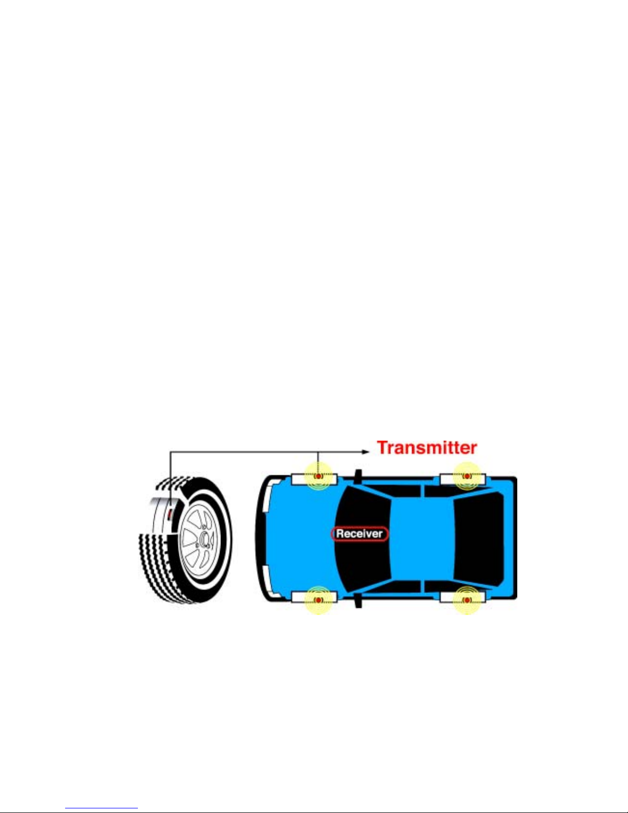
1. System Introduction
(1) TPV03 is a wireless tire pressure monitoring system with sensor/transmitter
mounted on each wheel pl us a set of Rec eiver with D isplay placed in dr iv er's cabi n.
Highly accurate sensors collect tire pressure and temperature data then
transmitted by wireless radio to Digital Receiver.
(2) The System monitors the data of tires with LCD digital display thus driver can be
well-informed with most updating data of tires while driving. The Digital Receiver
will alert immediately with beeps, bright yellow LED and backlight of LCD while
pressure and/or temperature are/is out of factory-preset critical limits. Therefore,
the product can alert the driver to the abnormal condition of tire pressure and/ or
tire temperature, and it will reduce the possible danger caused by abnormal tire
pressure and tire temperature.
2. Safety Notices
(1) The System is designed to measure and display the active data, i.e. pressure and
temperature, in tires, and provides the alert or warning when the System detects the
pressure or/and the temperature of tires is/are out of threshold setting. The driver
shall have the responsibility to react with attentiveness to the alert or warning.
Abnormal tire pressure and temperature should be checked and they should be
recovered to the normal values ASAP to avoid danger.
(2) This product has to be properly installed and programmed by qualified personnel
according to this User Manual.
3. Applicable Vehicles
This system is suitable for all kinds of 4-wheel vehicles less than 4500 kgs (10000
pounds).
4. System Package Content
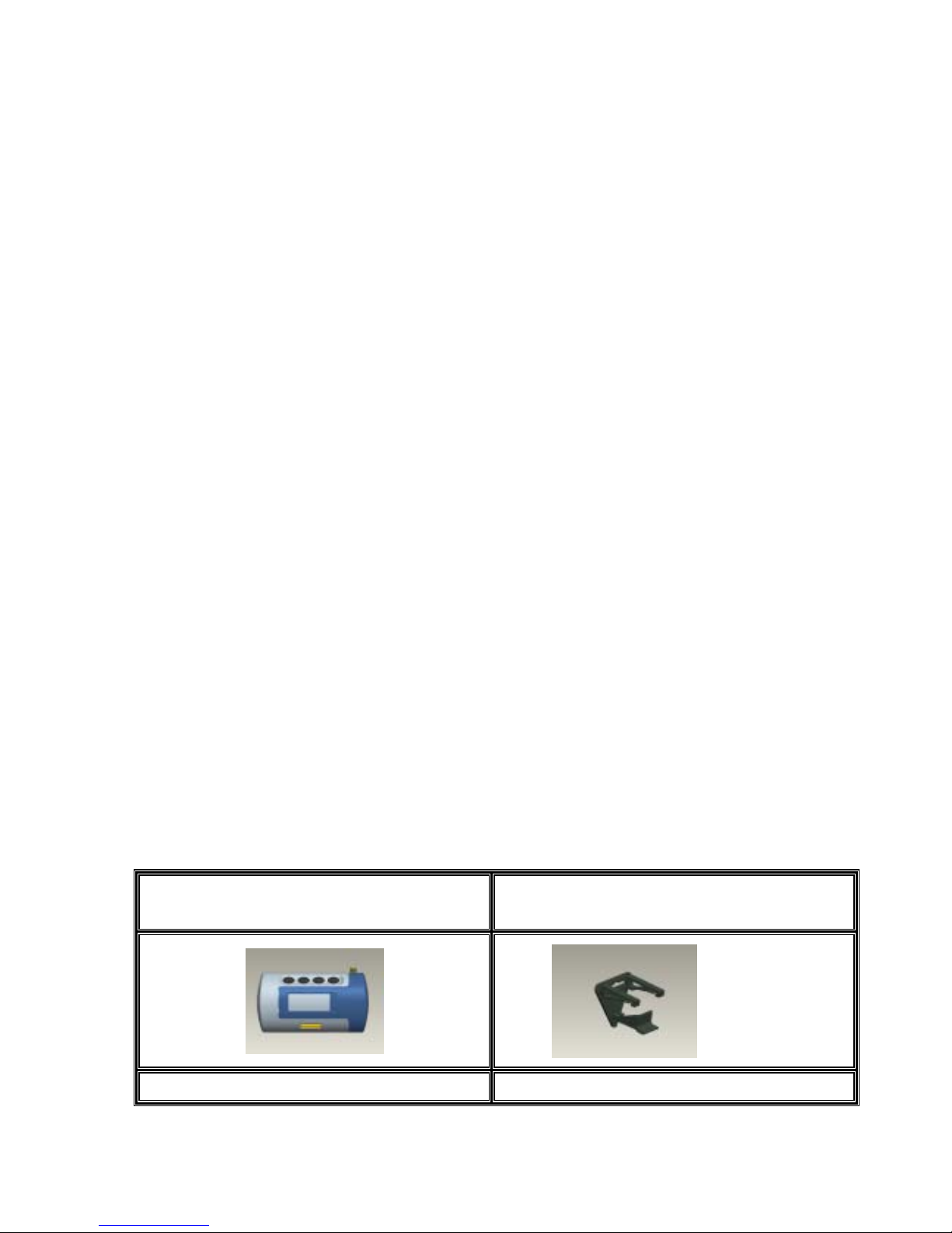
(1) Digital Receiver: 1 Unit (2) Cooling Vent Holder: 1 set ( inc. two
Fixing slices )
(3) Antenna: 1 Unit (4) DC Power Cable: 1 Unit
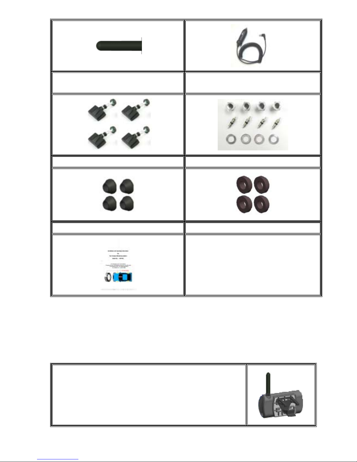
(5) Transmitter: 4 Units (6) Installation Parts for Transmitter (Nut,
Core and Washer – each 4 pcs )
(7) TX rubber ring A : 4 pc (8) TX rubber ring B : 4 pc
(7) User Manual: 1 pc
5. Operation and Installation of Wireless Tire Pressure
Monitoring System
5.1 Installation and Demounting of Digital Receiver
5.1.1 Utilize the Cooling Vent Holder to fasten the Digital Receiver onto the
Air Outlet in driver’s cabin
(1) Fasten the Cooling Vent Holder onto the backside of the
Digital Receiver.
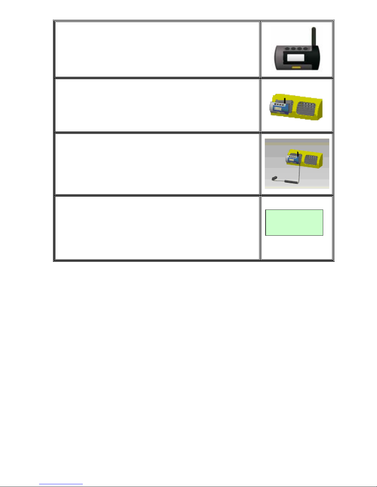
(2) Screw the Antenna into the Digital Receiver.
(3) Fasten the Digital Receiver with the Cooling Vent Holder onto
the Air Outlet in the front seat.
(4) Plug the DC Power Cable into the Vehicle Cigarette Lighter
Socket and Digital Receiver Power Jack.
(5) Turn on the Ve hic le Power and confirm if the LCD Display
shows 4 “??P”.
??P ??P
??P ??P
5.1.2 Replace Mounted-on-Air-Outlet Digital Receiver
(1) Disconnect Digital Receiver from Vehicle Cigarette Lighter Socket,
pay attention to the hanging way of the Cooling Vent Holder, then
take the Digital Receiver from the air outlet in the front seat carefully.
(2) Follow procedures 7.1 (1), (2), (3), (4), (5) to install a new Digital
Receiver.
5.2 Installation and Demounting of Transmitter
Caution:
The product should be i nst al led by qualified technicians. The technicians nee d t o
follow the installation procedures, making sure that the transmitters are properly
installed and undamaged.
The tools and instruction in this user manual are used by technicians from
vehicle manufacturer or garage. It is suggested that general consumer
cooperates with the responsible people from the purchasing place or the
authorized installati on g arage; g eneral consumer sho uld get pr ofessi onal trai ning ,
then he just could install the product by himself. Otherwise, Mobiletron, will not

offer any warranty if he installs the product by himself.
Tools Required:
Tire Changing Equipment
Tire Balancing Equipment
Torque Wrench
5.2.1 Mounting the Tire with Transmitter on Wheel Rim
Notes:
Pair Valve Tag that has the same color as the color of text on ID Number
Label of Transmitter for the identical tire as indicated in below brackets.
(1) Prepare the Transmitter to pass through the valve hole which is
positioned on the steel, aluminum or aluminum alloy wheel rim.
(2) Pass the Transmitter through the valve hole and the rubber
circle will push up the inside of the valve.
(3) Attach the Rubber Ring B that is the spare part of Transmitter
from the outside of the wheel rim onto the valve hole.
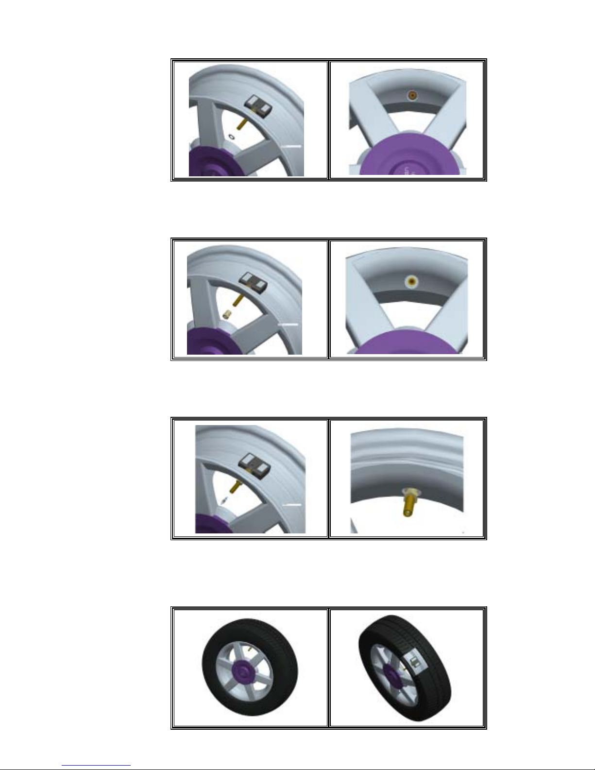
(4) Attach the Washer that is the spare part of Transmitter from the
outside of the wheel rim onto the valve hole.
(5) Attach the Core that is the spare part of Transmitter from the
outside of the wheel rim onto the valve hole.
( => Recommendatory Torque to attach t he Cor e: 2~3.2 Kgf.cm )
(6) Attach the Nut that is the spare part of the Transmitter from the
outside of the wheel rim onto the valve hole.
( => Recommendatory Torque to attach t he Nut : 35~45 Kgf.cm )
(6) Install the tire with the standard installation equipment, and
installation procedures could be proceeded by the technicians
from the purchasing place or the authorized installation ort.
 Loading...