

Page 1

GTR-660
User manual
T E L : 04- 2 2 3 8 - 0 6 9 8
F AX: 04- 2238- 0 891
Web Site:
E - m a i l: s a l e s @ m o n i c o n . c o m . t w
http://www.monicon.com.t w
[1]
Page 2
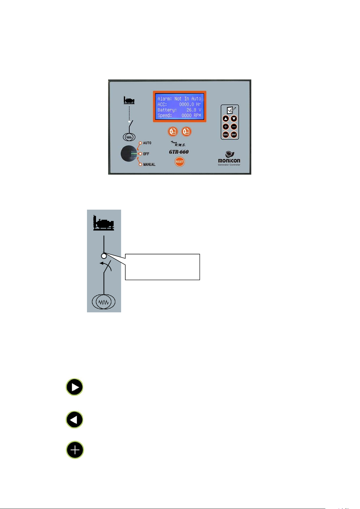
1. Introduction
Indication of circuit
breaker status
A. Panel descriptions
B. Circuit Breaker status LED
Genset Indicators:When ATS transfers load from Mains to the Genset, the LED turns ON if
connector 26 detects signal from ATS switch.
C. Setup Keypad
1. In password entry mode, this keypad switches to next digit.
2. Under PARAMETER setting, this keypad switches to the next parameter.
1. In password entry mode, this keypad switches to previous digit.
2. Under PARAMETER setting, this keypad switches to previous parameter.
1. In CODE entry mode, this keypad increases the value
2. Under PARAMETER setting, this keypad increases the setting value.
[2]
Page 3

1. In CODE entry mode, this keypad decreases the value.
2. Under the PARAMETER setting mode, this keypad decreases the setting
Enter or exit the parameter setting mode (Code: 0000)
Confirm and save the settings
These keypads alternately change the display of Genset information, evenlog,
and error code.
Press reset to clear error and deactivates alarm.
[3]
Page 4

D. Operation Rotary Switchs
Pin
Description
Code
2
Battery +
B+
3
Battery -
B-
4
Ground
GND
5
Crank output
Crank
6
Fuel pump output
Fuel
7
Stop output
Stop
8
Output 3
Out.3
9
Output 2
Out.2
10
Output 1
Out.1
11
Output 1
12
Output 0
Out.0
13
Output 0
18
Input 4
IN.4
19
Input 3
IN.3
20
Input 2
IN.2
1. Manual:In manual mode, the LCD shows pre-heat function; after pre-heat, engine starts
immediately. If engine fails to start, the GTR-660 returns to the OFF mode. The pre-heat
state may not perform, if parameter setting is disabled. If Pre-fuel is activated, the fuel
outputs before crank procedure.
2. AUTO:In the Auto mode, the GTR-660 starts the engine by ATS signal and then the LCD
shows preheat, if pre-heat function is enabled. After pre-heat, the engine starts to crank. If
engine fails to start, the system returns to the pre-heat state and then start to crank the
engine again. For example, if the conditions and parameter settings are given as follows:
1.stop duration is 10 seconds, crank attempt is 3 times. The engine cranks for 10 seconds
and then rest for 10 seconds, after 3 attempts, the LCD shows the over crank and triggers
the alarm.
3. OFF:Switch to OFF stops the engine and then “stop” appears on the LCD. The idle also
appears on the LCD, if the idle function is enabled. After 10 seconds of delay (depends on
the setting), the engine stops completely and idle icon disappears.
E. Rear connectors:
[4]
Page 5

21
Input 1
IN.1
22
ATS input
ATS
23
Input 0
IN.0
24
Low oil pressure switch
L.O.P
25
High water temperature switch
H.W.T.
26
Genset breaker status input
G. switch
27
N/A
28
Pickup (RPM)
Pick-up
29
Pickup (RPM)
Pick-up
49
CT 1 input
I1
50
CT 2 input
I2
51
CT 3 input
I3
52
CT Common input
Com.
53
Sensor V+ output
Sensor V+
54
Sensor Common GND input
Common
55
Oil pressure sensor input
Oil Press
56
Oil temperature sensor input
Oil Temp
57
Water temperature sensor input
Coolant Temp
58
AUX sensor input
Auxiliary
U
Generator U input
U V Generator V input
V
W
Generator W input
W
N
Generator N input
N R Mains R input
R
S
Mains S input
S
T
Mains T input
T N Mains N input
N
[5]
Page 6
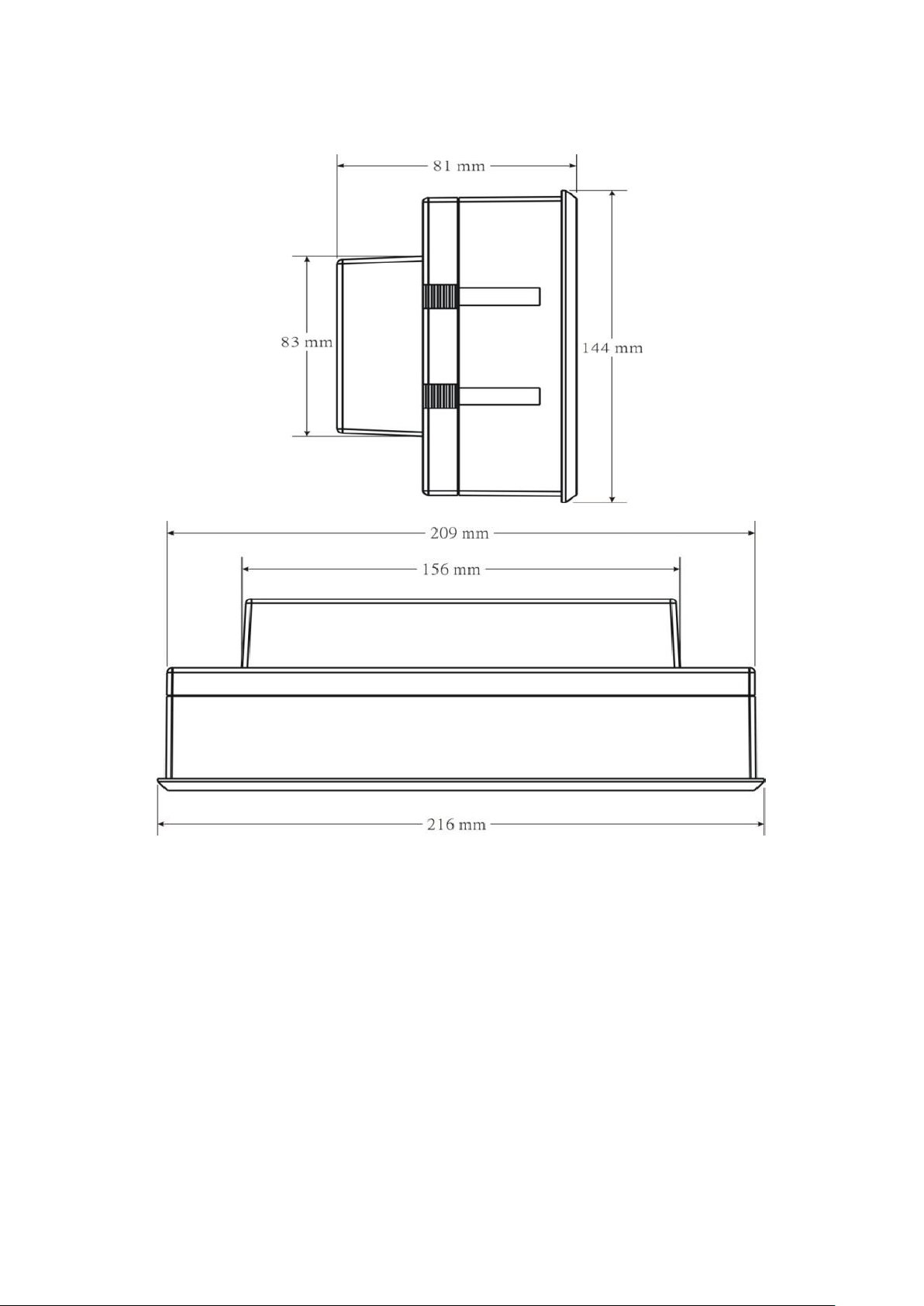
2. Dimension
[6]
Page 7

3. Specification
A. Display
1. Mains OFF warning
2. Fuel level
3. Frequency
4. AC voltage/current
5. KW KVA KVAR (3 phase)
6. P.F.
7. RPM
8. Engine parameter settings
9. Battery voltage
10. Exerciser
11. Water temperature
12. Oil pressure
13. 1024 Event log
14. 64 Error record
B. Remote access:
1. Start, stop, and reset
2. Parameter settings
3. Genset monitoring
4. Error code access
C. Front panel:
1. Manual
2. Auto (ATS)
3. OFF
4. Reset
[7]
Page 8

Engine
1.High water temperature
2.Low oil pressure
3.Low coolant
4.Over crank
5.Over speed
6.Low fuel
Generator
1.Over load
2.Short
3.High voltage
4.Low voltage
5.High frequency
6.Low frequency
Battery
1.Low voltage
2.High voltage
3.Charge fail
4.Under voltage
D. Protections
E. Specification
DC input: 8~36 VDC
Power consumption: Max. 24 W
Voltage measurement: 0~500VAC(±0.2 %)
Current measurement: 0~5 A * CT ratio (±0.2 %)
Frequency measurement: 0~80 Hz(±0.02 %)
Charger or pickup voltage: 5 V ~ 70 V(peak to peak)
Charger or pickup frequency:62 Hz ~ 5KHz
Relay output: 10 A/30 VDC (Output 3 Max. 1 A).
Communication protocol:A. Power environment Communication protocol
B. Modbus master Communication protocol
Working temperature: -10 ℃ ~ 60 ℃
Dimension(W * H * D): 216 mm * 144 mm * 89 mm
Opening(W * H): 210 mm * 138 mm
Weight: 1 Kg
[8]
Page 9

4. Genset Info.: Display generator inforamtion
A. Event Record: Display operation history
B. Parameter Modify:
1. Crank Settings
1. Detect Frequency
Setting:Disable/ Enable
Default:Enable
Description:Check frequency value before cranking the engine.
2. Detect oil press
Setting:Disable/ Enable
Default:Enable
Description:Check oil pressure before cranking the engine.
3. Crank interval
Setting:5~40(seconds)
Default:10
Description:Set the duration of each crank.
4. Crank attempts
Setting:1~10
Default:3
Description:Set total number of crank attempts.
5. Escape up limit
Setting:15~30(Hz)
Default:20
Description:When frequency reaches setting, starter motor disconnects from engine.
6. Engage low limit
Setting:15~30(Hz)
Default:20
Description:If frequency is below setting allows crank procedure
7. OP build up time
Setting:0.2~2.0(Seconds)
Default:0.6
8. Idle interval
Description:Time delay before disconnecting starter motor after oil pressure switch
activates. (“Detect oil press” must be enabled.)
Setting:0~600(Seconds)
[9]
Page 10

Default:0
Description:Duration of engine idle
2. Engine Settings
1. PreAdd Fuel Time
Setting:0.0~5.0(seconds)
Default:3
Description:Activates fuel pump before initiating crank procedure.
2. Pre-Heat Time
Setting:0~20(Seconds)
Default:0
Description:Duration of Preheat before crank.
3. Energied to Stop
Setting:1~30(seconds)
Default:10
Description:Output duration for stop solenoid to shut down the engine.
4. Failed to stop
Setting:1~10(Seconds)
Default:2
Description:Time delay before triggering engine shutdown failed alarm.
5. Trip then shut
Setting:Disable/ Enable
Default:Enable
Description:When error occurred, timer starts before shutdown the engine
6. Trip duration
Setting:30~900(Seconds)
Default:30
Description:When error occurred, controller outputs error signal, if error is not cleared
within setting, system initiates Genset shutdown.
7. Cooling time
Setting:0~1250(Seconds)
Default:30
Description:Set engine cooling time for normal Genset shutdown. Engine cooling time is
disabled during malfunction shutdown
8. Freq versus RPM
Setting:0~200
Default:30
Description: To conver RPM from frequency, divide RPM by frequency
(1800rpm/60HZ=30), 30 is the ratio for this setting.
[10]
Page 11

9. Man Inst. Stop
Setting:Disable/ Enable
Default:Enable
Description:Manual shutdown the Genset without cooling down the engine
3. Hour Meters
1. Acc.: Seconds/
Setting:0~59(Seconds)
Default:0
Description:Set the hour meter in seconds.
2. Acc.: Minutes
Setting:0~59(Minutes)
Default:0
Description:Set the hour meter in minutes
3. Acc.: Hour
Setting:0~99(Hour)
Default:0
Description:Set the hour meter in hours.
4. Acc.: Hour * 100
Setting:0~99(*100)
Default:0
Description:Set the hour meter in 100 hours scale.
4. Sensors Switches
1. H.W.T. Detection
Setting:Disable/ Enable
Default:Enable
Description:Activates high water temperature protection
2. H.T. Sw. Type
Setting:NC/NO
Default:Normal Open
Description:Setup the switch to normally close or normally open.
3. H.W.T. Sw. Delay
Setting:1~9.5(Seconds)
Default:1.5
Description:When high water temperature occurres, timer starts before initiating shutdown.
4. L.O.P. Detection
Setting:Disable/ Enable
[11]
Page 12

Default:Enable
Description:Activates low oil pressure protection
5. O.P. Sw. Type
Setting:NC/NO
Default:Norma close
Description:Setup the switch to normally close or normally open.
6. L.O.P Sw. Delay
Setting:0.2~6.0(Seconds)
Default:1
Description:When low oil pressure occurres, timer starts before initiating shutdown.
5. Auxiliary Input
1. Auto input delay
Setting:0.2~5(seconds)
Default:1
Description:Time delay for ATS input before initiating crank procedure.
2. Input0 Detect
Setting:Disable/ Enable
Default:Enable
Description:Activates Input 0 function
3. Input 0 Name
Setting:1.Emergency Stop 2.User Define 3.Low battery Voltage 4. System fault 5.High fuel
level 6. System trip 7.Insulation Fail 8.Cooling failure 9.Malfunction warning 10.Charge
fail 11.Over load 12.Low water temperature 13.Preheat
Default:Preheat
Description:Define the function for input 0
4. In0 Protection
Setting:1.Warning 2.Alarm 3.Trip 4.Stop)
Default:Stop.
Description:Setup the action when input 0 activates
5. In0 Switch Type
Setting:NC/NO
Default:Normal Close
Description:Setup input 0 to normally close or normally open
6. Input0 Delay
Setting:0.2~5.0(Seconds)
Default:0.2
Description:When input0 activates, timer starts before activating protection
7. Input 1 Detect
[12]
Page 13

Setting:Disable/ Enable
Default:Enable
Description:Activates input1 function
8. Input1 Name:1.Emergency Start 2.User Define 3.Low battery Voltage 4. System fault
5.High fuel level 6. System trip 7.Insulation Fail 8.Cooling failure 9.Malfunction warning
10.Charge fail 11.Over load 12.Low water temperature 13.Preheat
Default:4.
Description:Define function for input 1
9. In1 Protection
Setting:1.Warning 2.Alarm 3.Trip 4.Stop
Default:Stop
Description:Setup the action when input1 activates
10. In1 Switch Type
Setting: NC/NO
Default:Normal Open
Description:Define input1 type to normally close or normally open
11. In1 delay
Setting:0.2~5.0(Seconds)
Default:2.0
Description:When input1 activates, timer starts before activating protection
12. Input 2 Detect
Setting:Disable/ Enable
Default:Enable
Description:Activates input2 function
13. Input 2 Name
Setting:1.Low coolant level 2.User Define 3.Low battery Voltage 4. System fault 5.High
fuel level 6. System trip 7.Insulation Fail 8.Cooling Fan failure 9.Malfunction warning
10.Charge fail 11.Over load 12.Low water temperature 13.Preheat
Default:8.
Description:Define function for input 2
14. In2 Protection
Setting:1.Warning 2.Alarm 3.Trip 4.Stop
Default:2
Description:Setup the action when In2 activates
15. In2 switch type
Setting:NC/NO
Default:Normal Open
Description:Setup input2 to normally close or normally open
[13]
Page 14

16. Input2 Delay
Setting:0.2~5.0(Seconds)
Default:0.4
Description:When input2 activates, timer starts before activating protection
17. Input3 Detect
Setting:Disable/ Enable
Default:Enable
Description:Activates input3 function
18. Input 3 Name
Setting:1.Low fuel level 2.User Define 3.Low battery Voltage 4. System fault 5.High fuel
level 6. System trip 7.Insulation Fail 8.Cooling Fan failure 9.Malfunction warning
10.Charge fail 11.Over load 12.Low water temperature 13.Preheat
Default:6.
Description:Define function for AUX 3
19. In3 Protection
Setting:1.Warning 2.Alarm 3.Trip 4.Stop
Default:4.
Description:Setup the action when input 3 activates
20. In3 Switch Type
Setting:NC/NO
Default:Normal Open
Description:Setup Input 3 to normally close or normally open
21. Input3 Delay
Setting:0.2~5.0(Seconds)
Default:2
Description:When input 3 activates, timer starts before activating protection
22. Input4 Detect
Setting:Disable/ Enable
Default:Enable
Description:Activates input4 function
23. Input4 Name
Setting:1.Low fuel level 2.User Define 3.Low battery Voltage 4. System fault 5.High fuel
level 6. System trip 7.Insulation Fail 8.Cooling Fan failure 9.Malfunction warning
10.Charge fail 11.Over load 12.Low water temperature 13.Preheat
Default:5.
Description:Define function for input4
24. In4 Protection
[14]
Page 15

Setting:1.Warning 2.Alarm 3.Trip 4.Stop
1.All errors
2. Trip
3.Preheat
4.Idle
5.Reset
6.Main breaker On
7.Main breaker hold
8. Genset power normal
9.Engine running
10.Over crank
11.Over speed
12.Over frequency
13.Low frequency
14.Low oil
pressure(switch)
15. High water
temperature(switch)
16.High AC voltage
17.Low AC voltage
18.Overload
19.Short circuit
20.Low battery voltage
21.High battery voltage
22.Input 0 activate
23.Input1activate
24.Input 2 activate
25. Input 3 activate
26.Input 4 fault
27.High water temp.
28.Low oil pressure
29.Low fuel level
30.High fuel level
31.System not in AUTO
32.System in AUTO
33.Manual Start
34.AUTO Start
35.Standby mode
36.Pre-heat
37.Pre-fuel
38.Cranking
39.Crank cycle
40.System normal
41.System Alarm
42.System Trip
43.Engine shutdown
44.Engine Cooling
45. Sensor fail
46. Charge fail
47. Reverse power
48. Over load
Default:2.
Description:Setup the action when input 4 activates
25. In4 Switch Type
Setting:NC/NO
Default:Normal Open
Description:Setup Input 4 to normally close or normally open
26. Input4 Delay
Setting:0.2~5.0(Seconds)
Default:0.4
Description:When input 4 activates, timer starts before activating protection
6. Auxiliary Output
1. Output 0 function
Setting:1~48
Default:20.
Description:Setup the function for output 0
2. Output 1 function
Setting:1~48
Default:1.
Description:Setup the function for output 1
3. Output 2 function
Setting:1~48
Default:8.
Description:Setup the function for output 2
[15]
Page 16

4. Output 3 function
Setting:1~48
Default:42.
Description:Setup the function for output 3
5. Output 4 function
Setting:1~48
Default:43.
Description:Setup the function for output 4
7. Frequency
1. System Frequency
Setting:50/60(Hz)
Default:60
Description:Setup Genset frequency in 50Hz or 60Hz
2. Hi Freq. Detect
Setting:Disable/ Enable
Default:Enable
Description:Activates high frequency protection
3. H.F. set point
Setting:50~60/60~72(Hz)
Default:55/66Hz
Description:When AC frequency is higher than setting, controller shuts down the engine
and display high frequency error, if high frequency protection is enable.
4. Hi Freq. Delay
Setting:1~9(Seconds)
Default:1
Description:When high frequency occurres, timer starts before activating protection
5. Low frequency Detect
Setting:Disable/ Enable
Default:Enable
Description:Activates low frequency protection
6. L.F. Protection
Setting:1.Warning 2.Alarm 3.Trip 4.shutdown
Default:2
Description:Setup the action when low frequency occurs
7. L.F Set Point
Setting:40~50/48~60(Hz)
Default:45/55Hz
[16]
Page 17

Description:When AC frequency is lower than setting, controller outputs trip signal.
8. Low Freq. Delay
Setting:1~9(seconds)
Default:3
Description:When low frequency occurres, timer starts before activating protection
9. Mini. Freq. Det
Setting:Disable/ Enable
Default:Enable
Description:Activates minimum low frequency protection.
10. M.F. set point
Setting:30~48(Hz)
Default:36
Description:When sudden drop of frequency belows setting; low frequency protection
automatically disables and engine operates at idle speed.
8. Battery
1. System DC volt
Setting:12/24(V)
Default:12
Description:Setup DC voltage in 12V or 24V
2. Batt. Fault Alarm
Setting:Disable/ Enable
Default:Enable
Description:Activates battery error protections
3. L batt Set Point
Setting:8.4~12/16.8~24(V)
Default:10.8/20
Description:When battery voltage is below setting, controller displays low DC volt
warning.
4. H batt Set Point
Setting:12~16.8/24~33.6(V)
Default:14.4/28.4
Description:When battery voltage is above setting, controller displays high DC volt
warning.
5. Weak Batt. Detect
Setting:Disable/ Enable
Default:Enable
Description:Activates weak battery protection
6. W. Batt. Set Point
[17]
Page 18

Setting:4.8~8.4/9.6~16.8(V)
Default:8.4/9.6
Description:When battery voltage is below setting, controller displays battery warning.
7. Charge failed
Setting:9.6~14.4/19.2~28.8(V)
Default:12.6/22.6V
Description:When voltage is out of range, controller displays charge fail.
9. AC Voltage
1. Gen. Output volt
Setting :
110/120/190/208/220/380V/415/440V/480V/660V/3300V/4160V/6600V/7620V/11400V
Default:380V
Description:Setup Genset AC output voltage
2. System AC Volt
Setting:110/120/190/208/220/240/380V/415/440
Default:380V
Description:Setup controller AC input voltage
3. Hi ACV Detect
Setting:Disable/ Enable
Default:Enable
Description:Activates high voltage protection.
4. Hi ACV Protect
Setting:1.Warning 2.Alarm 3.Trip 4.Stop
Default:3
Description:Setup the action when high voltage occurs.
5. Hi ACV Set Point
Setting:110~132/120~144/190~228/208~250/220~264/380~456(V)
Default:122/122/210/242/242/418
Description:When AC voltage is above the setting, the controller outputs trip signal.
6. Hi ACV Delay
Setting:0.5~5(Seconds)
Default:2.5
Description:When high voltage occurred, timer starts before activating protection
7. Low ACV Detect
Setting:Disable/ Enable
Default:Enable
Description:Activates low voltage protection
8. Low ACV Protection
[18]
Page 19

Setting:1.Warning 2.Alarm 3.Trip 4.Stop
20:5
30:5
40:5
50:5
60:5
75:5
80:5
100:5
150:5
200:5
250:5
300:5
400:5
500:5
600:5
700:5
750:5
800:5
900:5
1000:5
1200:5
1500:5
1600:5
2000:5
2500:5
3000:5
3200:5
4000:5
5000:5
6000:5
Default:3
Description:Setup the action when low voltage occurs
9. Low ACV set point
Setting:78~110/84~120/134~190/146~208/154~220/266~380(V)
Default:108/108/172/198/198/342
Description:When AC voltage is below setting, controller outputs trip signal
10. Low ACV delay
Setting:0.5~5(Seconds)
Default:2.5
Description:When low voltage occurred, timer starts before activating protection
11. Mini. ACV Detect
Setting:Disable/ Enable
Default:Enable
Description:Activates extreme low voltage protection.
12. Mini. ACV setpoint
Setting:34~88/36~96/58~152/62~166/66~176/114~304(V)
Default:56/60/96/110/110/198
Description:When sudden drop of AC voltage blows setting, low voltage protection is
disabled.
13. ACV Escape Motor
Setting:Disable/ Enable
Description:Disengage starter motor by Genset voltage
14. Esc. ACV Setpoint
Setting:44~100/48~108/76~172/84~188/88~198/152~342(V)
Default:72/72/124/124/132/228
Description:Disconnect starter motor when AC Voltage reaches disconnecting setting
10. AC Ampere
1. Current Ratio:
Range:
Default:500:5
Description:Setup the current transformer ratio
[19]
Page 20

2. Over load Detect:
0.1~20.0(A)
0.1~30.0(A)
0.1~40.0(A)
0.1~50.0(A)
0.1~60.0(A)
0.1~75.0(A)
0.1~80.0(A)
0.2~100.0(A)
0.3~150.0(A)
0.4~200.0(A)
5.0~250.0(A)
6.0~300.0(A)
8.0~400.0(A)
10.0~500.0(A)
12.0~600.0(A)
14~700.0(A)
15.0~750.0(A)
16.0~800.0(A)
18.0~900.0(A)
20.0~1000.0(A)
24.0~1200.0(A)
30.0~1500.0(A)
32.0~1600.0(A)
40.0~2000.0(A)
50.0~2500.0(A)
60.0~3000.0(A)
64.0~3200.0(A)
80.0~4000.0(A)
100.0~5000.0(A)
120~6000(A)
1~5(A)
2~10(A)
3~15(A)
4~20(A)
6~30(A)
8~40(A)
10~50(A)
12~60(A)
15~75(A)
16~80(A)
20~100(A)
30~150(A)
40~200(A)
50~250(A)
60~300(A)
80~400(A)
100~500(A)
120~600(A)
150~750(A)
160~800(A)
180~900(A)
200~1000(A)
240~1200(A)
300~1500(A)
320~1600(A)
Setting:Disable/ Enable
Default:Enable
Description:Activates overload protection
3. Over load Protection:
Setting:1.Warning 2.Alarm 3.Trip 4.Stop
Default:3
Description:Setup the action when overload occurs
4. O. L. Set Point:
Range:1~31
Description:When current is above setting, the controller outputs trip signal, setup range is
related to the CT ratio.
5. Overload Delay:
Setting:10~300(Second)
Default:40
Description:When overload occurres, timer starts before activating protection
6. Short Detect:
Setting:Disable/ Enable
Default:Enable
Description:Activates AC short protection
7. Short protect:
Setting:1.Warning 2.Alarm 3.Trip 4.Stop)
Default:4
Description:Setup the action when AC short occurs
8. Short Set Point:
Setting:1~31
[20]
Page 21

400~2000(A)
500~2500(A)
600~3000(A)
640~3200(A)
800~4000(A)
1000~5000(A)
Description:When current is above the setting, controller outputs trip signal, setup range is
related to the CT ration setup.
9. Short Delay:
Setting:0.1~1.0(Second)
Default:0.2
Description:When AC short occurres, timer starts before activating protection
11. RPM
1. RPM Mul. Factor
Setting:1~200
Default:60
Description:Please use value calculated in next parameter setting
2. RPM Div. Factor
Setting:1~200
Default:40
Description:The R.P.M. Mul. and Div. are the ratio of engine revolution versus total number
of fly wheel teeth; or the RPM of fly wheel versus the RPM of alternator charger. For
example: Set up the RPM numerator and the denominator to 1 to find input pulse from the
LCD.
(A) If the engine revolution is 1800 and alternator revolution is 460 (input pulse), the R.P.M.
numerator could be set to 90→ (1800÷20) and R.P.M. denominator could be set to 23→(460÷
20).
Solution: 1800 / 460 = 3.913
The R.P.M. calculation formula is as below
R.P.M. = Input pulse * (RPM numerator / RPM denominator)
1800 = 460 * (90/23)
(B) If the engine revolution is 1500 and total count of fly wheel teeth in one second is 4437 (input
pulse), the R.P.M. numerator should be set to 45 and R.P.M. denominator should be set to 133.
Solution: 1500 / 4437 = 0.338
The R.P.M. calculation formula is as below
R.P.M. = Input pulse * (revolution numerator / revolution denominator)
1500 = 4437 * (45/133)
(C) If the teeth count of engine flywheel is 118. Assume the rated rpm of Gen-set is 1500
rpm. Then the 1500 rpm/50hz => 30 rpms/per second also generate 30 x 118 =3540
electronic signals. Then 1500 / 3540 = 0.423 (75/177=0.423), set the R.P.M. numerator to
75 and R.P.M. denominator to 177.
3. RPM Escape motor
[21]
Page 22

Setting:Disable/ Enable
Default:Disable
Description:Disengage starter motor by RPM setting
4. RPM Esc. Set point
Setting:300~900(RPM)
Default:480
Description:Disconnect starter motor when RPM reaches setting
5. RPM Disp. Source
Setting: Alternator / Frequency
Default:Freq.
Description:Converts the RPM from frequency or alternator speed.
6. O.S. Detection
Setting:Disable/ Enable
Default:Enable
Description:Activates over speed protection.
7. O.S. set point
Setting:1350~2100(RPM)
Default:1980
Description:If engine speed is higher than setting, controller shuts down the engine only if
over speed is enabled
8. Over speed delay
Setting:1~10(Second)
Default:1
Description:When over speed occurres, timer starts before activating protection
12. Sensors
1. LFL Value Alarm
Setting:Disable/ Enable
Default:Enable
Description:Activates low fuel warning
2. LFL set point
Setting:6~55(%)
Default:45
Default:When fuel level is below setting, controller displays warning message.
3. HFL set point
Setting:35~99(%)
Default:95
Description:When fuel level is above setting, controller displays warning message
4. LOP value alarm
[22]
Page 23

Setting:Disable/ Enable
VDO 10 Bar
KD 10 Bar
YG 962
N 010 B2
KL 3967251
MHI 10 Bar
DATCON 10 Bar
SUSUKI 10 Bar
VDO 5 Bar
KP 6 Bar
KAMAZ
Betung
Weichai
Betung 3317-EPT
VDO 120
KD 120
WGI 900131
KP130
YB 054
KL 3967250
MHI 98
SUSUKI
PRO
SCD
Betung
User Define
SUSUKI
Betung
User Define
Default:Enable
Description:Activates low oil pressure warning
5. LOP set point
Setting:15~60(PSI)
Default:15
Description:When oil pressure is below setting, controller displays warning message
6. HWT Value Alarm
Setting:Disable/ Enable
Default:Enable
Description:Activates high water temperature protection.
7. HWT set point
Setting:85~110(℃)
Default:105
Description:When water temperature is above setting, controller displays warning message
8. OP Escape motor
Setting:Disable/ Enable
Default:Disable
Description:Disconnect starter motor when oil pressure reaches setting.
9. Esc. OP Set point
Setting:25~65(PSI)
Default:45
Description:Disconnect starter motor when oil pressure reaches setting.
10. OP Sensor Brand
Setting:
Description:Setup oil pressure sensor brand.
11. WT sensor Brand
Setting:
12. FL sensor Brand
Description:Setup water temperature sensor brand
Setting:
[23]
Page 24

Description:Setup fuel sensor brand
13. Check before start
Setting:Disable/ Enable
Default:Disable
Description:Setup the system to check sensors during controller boot up.
14. Cel. Or Feh
Setting:°F /℃
Default:
℃
Description:Setup water temperature unit in Fahrenheit or Celsius.
15. P.S.I or Bar
Setting:BAR /PSI
Default:PSI
Description:Setup oil pressure unit in Bar or PSI
13. Exerciser funct.
1. Exercise Funct.
Setting:Disable/ Enable
Default:Enable
Description:Activates exerciser function.
2. Date/ week Depend
Setting: Date/Week
Default:Date
Description:Setup monthly exercise by date or week.
3. Date set point
Setting:1~31(date)
Default:28
Description:Setup date of monthly exercise
4. Week set point
Setting:Sunday/Monday/Tuesday/Wednesday/Thursday/Friday/saturday
Default:Sunday
Description:Setup week of monthly exercise
5. Hour set point
Setting:0~23(hour)
Default:12
Description:Setup the starting hour of the exercise
6. Minute set point
Setting:0~59(minute)
Default:0
Description:Setup the starting minute of the exercise
[24]
Page 25

7. Running Interval
0.08~20.0(KW)
0.1~30.0(KW)
0.1~40.0(KW)
0.1~50.0(KW)
0.1~60.0(KW)
0.1~75.0(KW)
0.1~80.0(KW)
0.2~100.0(KW)
0.3~150.0(KW)
0.4~200.0(KW)
5.0~250.0(KW)
6.0~300.0(KW)
8.0~400.0(KW)
10.0~500.0(KW)
12.0~600.0(KW)
Setting:0~510(minute)
Default:4
Description:Setup the duration of each exercise
14. Maintain
1. Maintain Funct.
Setting:Disable/ Enable
Default:Disable
Description:Activates service reminder function
2. Maintain Protect
Setting:1.Warning 2.Alarm 3.Trip 4.Stop
Default:4
Description:Setup the action when service reminder reaches setting
3. Maintain Code 0
Setting:0~99
Default:12
Description:Setup first two digits of service password
4. Maintain Code 1
Setting:0~99
Default:15
Description:Setup remaining digits of service password
5. Maintain DnCount
Setting:0~1275(hour)
Default:250
Description:Setup the duration between each service
15. OverLoad Protect
1. Over Load Detect
Setting:Disable/ Enable
Description:Activates over load detection.
2. Overload protect
Setting:1.Warning 2.Alarm 3.Trip 4.Stop
Description:Setup the action when over load occured
3. O. Load Setpoint
Setting:
[25]
Page 26

14~700.0(KW)
15.0~750.0(KW)
16.0~800.0(KW)
18.0~900.0(KW)
20.0~1000.0(KW)
24.0~1200.0(KW)
30.0~1500.0(KW)
32.0~1600.0(KW)
40.0~2000.0(KW)
50.0~2500.0(KW)
60.0~3000.0(KW)
64.0~3200.0(KW)
80.0~4000.0(KW)
100.0~5000.0(KW)
120~6000(KW)
Description:Setup the Earth fault amperage limit
4. Over Load Delay
Setting:1~20(Seconds)
Description:When Earth fault reaches setting, timer starts before activating protection
16. Others
1. Protect Pending
Setting:1~30 (seconds)
Default:10
Description:Time delay for displaying warning or error messages after engine starts.
2. Language
Setting:English/Chinese
Default:English
Description:Choose between English or Chinese language
3. Comm. Address
Setting:0~255(00H~FFH)
Default:FFH
Description:Multiple Genset networking via RS-485 requires individual address for each
controller.
4. Not in AUTO Mode
Setting:Disable/ Enable
Description:When GTR-220 is in OFF mode, controller triggers alarm.
5. Contrast Adjust
Setting: 1~19
Description : Adjust contrast of LCD screen
17. Utility Charge
1. Cgr. In. Volt Low
Setting:100~198
Default:100
Description: Setup utility
2. Cgr. In. Volt High
Setting:110~242
Default:100
3. Util.Charge Fail
Description: Setup utility
[26]
Page 27

Setting:1.Warning 2.Alarm 3.Trip 4.Stop
Default:2
Description:Setup utility fail protection.
C. Error Record: Display Malfunction history
D. Miscellaneous
1. Time setting:
Description:Setup real time clock
2. User Code:
Description:Reset user password
3. Maintain Code:
Description:Reset engineer password
4. Crank information:
Description:
a. Total count: Display total number of crank attempts.
b. Fail count: Display total number of crank fail.
c. Succeed count: Display total number of successful cranks.
d. .Reset counters: Clears crank information(Password required)
[27]
 Loading...