

Monico CDL Gateway, CMS-MCGT-PCML-KIT, CMS-MCLE-PCML-K, CMS-MCGT-PCCx.XL-KIT, CMS-MCLE-PCCx.XL-KIT Installation And Operation Manual

Monico Gateway from Cummins®
Version
Installation and Operation Guide
1.03
Monico, Inc.
18530 Klein Church Road
Spring, TX 77379
281.350.8751
sales@monicoinc.com

- 2 -
V1.03
15.4.29
Table of Contents
1 Introduction .................................................................................................................................................... 4
2 Power Supply .................................................................................................................................................. 6
3 EMC Installation Guidelines ........................................................................................................................... 8
4 Installation ...................................................................................................................................................... 9
4.1 Connection and Engine Controller ....................................................................................................... 10
4.1.1 Monico PCML Gateway to Modlon Gateway .................................................................................. 10
4.1.2 Monico PCCx Gateway to PCC1.x/PCC2.x/PCC3.x Controller .......................................................... 11
4.2 Troubleshooting LEDs........................................................................................................................... 12
STS – Status LED ...................................................................................................................................... 12
4.3 Host Connections ................................................................................................................................. 13
5 MONICOVIEW II™ PROGRAMMER ............................................................................................................... 14
5.1 USB Driver Installation ......................................................................................................................... 14
5.1.1 USB Driver Troubleshooting ............................................................................................................ 15
5.2 Window Layout .................................................................................................................................... 16
5.2.1 The Navigation Pane ....................................................................................................................... 16
5.2.2 The Resource Pane .......................................................................................................................... 16
5.2.3 The Editing Pane .............................................................................................................................. 16
5.3 Obtaining/Updating the Gateway Configuration ................................................................................. 17
5.4 Setting the IP Address .......................................................................................................................... 17
5.5 Enabling TCP/IP Download ................................................................................................................... 18
5.6 Securing the Configuration (Optional) ................................................................................................. 19
5.7 Adjusting Serial Port Settings ............................................................................................................... 19
5.8 Enable/Disbale Devices ........................................................................................................................ 20
5.9 Viewing Live [Real Time] Data .............................................................................................................. 20

- 3 -
6 Configuration and Setup Of The Gateway PLUS........................................................................................... 22
6.1 The Web Server .................................................................................................................................... 22
6.1.1 Web Server Properties .................................................................................................................... 22
6.1.2 Using the Security System ............................................................................................................... 23
6.1.3 Using Services .................................................................................................................................. 25
6.1.4 Using Electronic Mail ....................................................................................................................... 27
6.2 Accessing the Virtual HMI .................................................................................................................... 32
7 APPENDIX A – Gateway Serial Ports ............................................................................................................. 34
8 Appendix B - SPECIFICATIONS ...................................................................................................................... 35

- 4 -
V1.03
15.4.29
1 Introduction
This document covers the installation and setup of the Monico Gateway from Cummins®. The
Monico Gateway™ KIT from Cummins® offers an easy to install, preconfigured protocol converter
specially designed for Cummins Power Generation applications. Each KIT comes complete with all
required accessories, instructions and user manual to perform and support most standard
installations encountered. Your Monico Gateway provides data conversation for generators with
PCC1.x, 2.x and 3.x as well PCC2100, PCC3200 and PCC3100 series controllers to three standard
preconfigured protocols: BACnet UDP, SNMP and Modbus TCP. All data is pre-scaled in standard
units with gains applied for effortless integration into your PLC, SCADA, BMS or PC system. In
addition to protocol conversion the Monico Gateway PLUS™ provide a web server, security
manager, FTP access and synchronization, virtual HMI, data logging, SMTP / SMS alert notification
and custom logic capabilities.
When you are correctly connected you can view live data with the use of MonicoView II software
which is available at http://www.monicoinc.com. All data values are in pre-assigned registers to
minimize setup time. It is our intention to always provide a product that requires little or no setup
to function in a wide variety of applications. However, any of our programs are modifiable using
MonicoView II software. Be sure to check the website for the latest software revisions before
installation. The major features are listed below:
•
Standard Version offers BACnet, SNMP, and Modbus TCP, over Ethernet. Serial interfaces on the
above mentioned protocols can be provided using an optional serial interface card
•
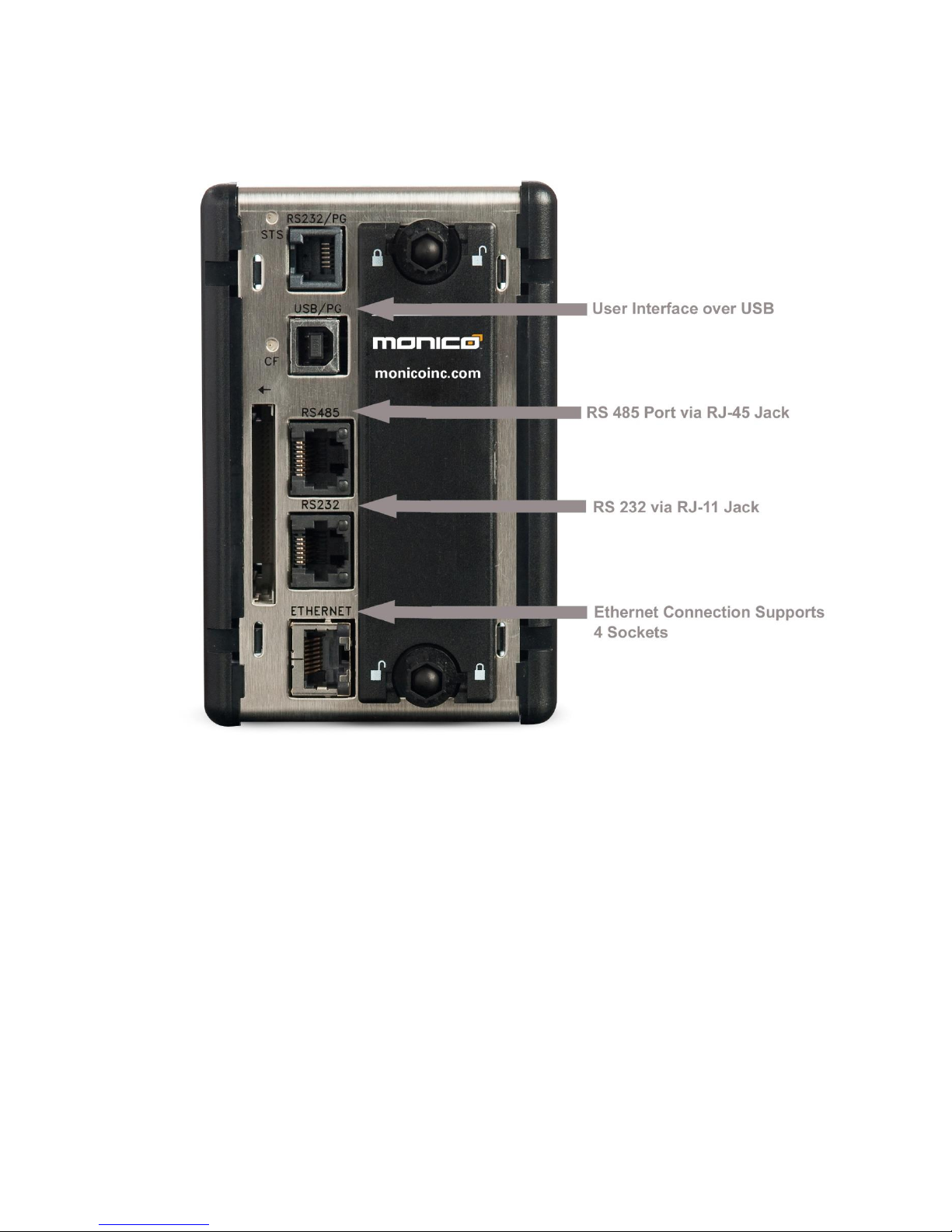
User Interface via a USB connection that allows you to configure the ports and see exactly
which parameters are responding on your installation.
• I
ntegral 24 VDC Power Supply
•
Designed to be mounted on Din-Rails, so no adapters are needed
•
Uses modular jacks for connections which minimizes wiring errors, especially when using our
optional factory cables
•
Does not require complicated address offsets.
•
Does not require complicated Enable/Disable Masks as all parameters are default enabled. If
necessary, the user can deactivate individual registers or ports via the User Interface, but due to
the drastic increase in speed it should not be necessary for monitoring purposes
•
Allows for other host protocols such as BACnet and can push parameters directly to the end
PLC, SCADA, or BMS system. Special instructions for these versions are covered in the appendix
sections of this manual.
As always, you can count on Monico’s “No Questions Asked” support policy. We are committed to
timely support of every customer who contacts us for help regardless of where the gateway was
purchased. The only thing that matters to Monico is a successful installation.
- 5 -
Gateway Connection Overview
Figure 1
- 6 -
V1.03
15.4.29
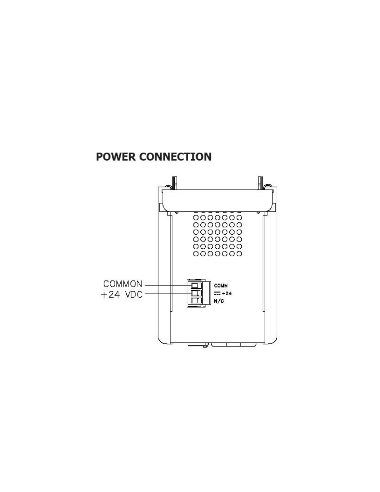
2 Power Supply
All Monico Gateways™ require a regulated 24 VDC +/- 10% power source with 1000 ma power maximum.
Monico Gateway from Cummins® KITS come with a 110 VAC-24 VDC power supply. If 110 VAC is not
available, you must use a Class 2 or SELV rated 24 VDC power supply. It is recommended that you use
either an isolated DC-DC power supply, or properly grounded engine 24v batteries to power the
Gateway. When power is applied, the green STS light will function. If this light is blinking, then no setup
file is installed or it is currently loading a file. If this light is solid, then a setup file is resident and
operating.
CAUTION
Reversing wire polarity may cause damage to your Gateway. This damage is not covered by warranty. If
in doubt about which wire is which on your power supply, check with a meter.
When using an external power supply, it is very important that the power supply is mounted correctly if
the unit is to operate reliably. Please take care to observe the following points:
The power supply must be mounted close to the unit, with usually not more than 6 feet (1.8 m) of cable
between the supply and the Gateway. Ideally, the shortest length possible should be used. The wire used
to connect the Gateway’s power supply should be at least 22-gage wire. If a longer cable run is used, a
Figure 2

- 7 -
heavier gage wire should be used. The routing of the cable should be kept away from large contactors,
inverters, and other devices which may generate significant electrical noise.
A power supply is provided with all Monico Gateway from Cummins® Kits and has a rating of Class 2 or
SELV. A Class 2 or SELV power supply provides isolation to accessible circuits from hazardous voltage levels
generated by a mains power supply due to single faults. SELV is an acronym for “safety extra-low voltage.”
Safety extra low voltage circuits shall exhibit voltages safe to touch both under normal operating
conditions and after a single fault, such as a breakdown of a layer of basic insulation or after the failure of a
single component has occurred.

- 8 -
V1.03
15.4.29
3 EMC Installation Guidelines
Although all Monico Gateways™ are designed with a high degree of immunity to Electromagnetic
Interference (EMI), proper installation and wiring methods must be followed to ensure compatibility in
each application. The type of electrical noise, source or coupling method into a unit may be different for
various installations. Cable length, routing, and shield termination are very important and can mean the
difference between a successful or troublesome installation. Listed are some EMI guidelines for a
successful installation in an industrial environment.
To reduce the chance of noise spikes entering the unit via the power lines, connections should be
made to a clean source. Connecting to circuits that also power loads such as contactors, relays, motors,
solenoids etc. should be avoided.
The unit should be mounted in a metal enclosure, which is properly connected to protective earth.
Use shielded (screened) cables for all Signal and Control inputs. The shield (screen) pigtail connection
should be made as short as possible. The connection point for the shield depends somewhat upon the
application.
Listed below are the recommended methods of connecting the shield, in order of their effectiveness.
o Connect the shield to earth ground (protective earth) at one end where the unit is mounted.
o Connect the shield to earth ground at both ends of the cable, usually when the noise source
frequency is over 1 MHz.
o Connect the shield to common of the Data Station and leave the other end of the shield
unconnected and insulated from earth ground.
Never run Signal or Control cables in the same conduit or raceway with AC power lines,
conductors feeding motors, solenoids, SCR controls, and heaters, etc. The cables should be
run through metal conduit that is properly grounded. This is especially useful in applications
where cable runs are long and portable two-way radios are used in close proximity or if the
installation is near a commercial radio transmitter. Also, Signal or Control cables within an
enclosure should be routed as far away as possible from contactors, control relays,
transformers, and other noisy components.
Long cable runs are more susceptible to EMI pickup than short cable runs. Therefore, keep
cable runs as short as possible.
In extremely high EMI environments, the use of external EMI suppression devices is effective.
The following EMI suppression devices (or equivalent) are recommended: Ferrite Suppression
Cores for signal and control cables:
o Fair-Rite part number 0443167251 (RLC part number FCOR0000) TDK part number ZCAT3035-
1330A
o Steward part number 28B2029-0A0
o Line Filters for input power cables:
o Schaffner part number FN610-1/07 (RLC part number LFIL0000) Schaffner part number FN670-
1.8/07
o Corcom part number 1 VR3

- 9 -
4 Installation
The DIN rail should be mounted horizontally so that the unit’s ventilation holes are vertical in relation to
cabinet orientation. A minimum clearance of 1 inch (25.4 mm) should be maintained above and below all
units in order to ensure proper thermal regulation. Also ensure that enough cable clearance is allowed at
the front of the Gateway to allow cable connections to the Gateway’s interface ports.
- 10 -
V1.03
Modlon Gateway
DB9 Connector
PCC Controller
[PCC2100 shown]
LonWorks Network
Monico Gateway
Monico CBL
-
DB
9
MNMRJ
12
-
1
RJ
12
to DB
9
Cable
Power [min 22 gage]
Power
Supply
Figure 4
15.4.29
Connection and Engine Controller
4.1.1 Monico PCML Gateway to Modlon Gateway
This section covers the installation and connection of the Monico PCML LE or GT Gateway to
Cummins Controllers and Transfer Switch Gear which employ the Lonworks network. Connection
interface between the Monico Gateway and Lonworks network is made via the Cummins Modlon
Gateway. Each Modlon Gateway supports up to 5 Engines and 5 Transfer Switches and each
device must have a Lonworks Network card installed. Subsequently, the standard Monico PCML
Gateway configuration is setup to support up to 5 Engines and 5 Transfer Switches via a single
Cummins Modlon Gateway.
The CMS-MCGT-PCML-KIT and CMS-MCLE-PCML-KIT come with the following hardware. Please
locate and ensure that you have the following. Contact Monico or your local Cummins Dealer if
any of items are missing.
o QTY (1) Monico Gateway
o QTY (1) CBL-DB9MNMRJ12-1, 1’ RJ12 to DB9 serial cable
o QTY (1) PQS3.241, 110VAC to 24VDC, 1 Amp power Supply
Please review section 3, EMC Installation Guidelines before proceeding.
Locate and install the Monico Gateway and Power Supply to a DIN rail mount.
Ensure that the Cummins Modlon Gateway is mounted next to the Monico Gateway as shown in
Figure 4
Plug the RJ12 connection end of the serial cable into the Monico’s RS232 port and the DB9 end
into the top of the Modlon Gateway.
Connect 24vdc from the power supply to both the Monico Gateway and Cummins Modlon
Gateway.
By default, the Monico Gateway is set to communicate with the Cummins Modlon Gateway via
Modbus RTU on RTU#1 at communication parameters of 38400 baud, 8 data bits , no parity, 1
stop bit (38400,8,N,1). Ensure that the Modlon Gateway is configured appropriately and once it
has been commissioned, apply power to the system.
Note the LED activity on the RS232 port of the Monico Gateway. If it is communicating properly,
you should see both the red and green LEDs alternating at a fast rate. If they are not, see section

- 11 -
Belden 984x
B(+)
TB15
[Shield] TB15-1
(+) TB15-3
(-) TB15-4
Monico Gateway
PCC 1.x/2.x/3.x Controller
C (-)
Monico CBL
-
485
-
1
RJ
45
to Flying Lead
B (+)
C (-)
Recommended Dip Switch
Settings [9600,8,N,1]
Isloated
Repeater
Power [min 22 gage]
Power
Supply
Figure 5
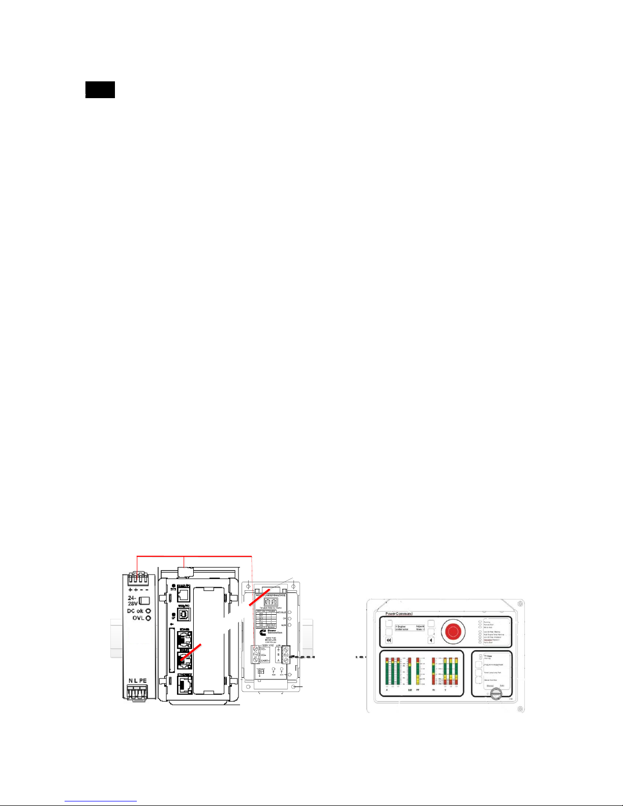
4.1.2 Monico PCCx Gateway to PCC1.x/PCC2.x/PCC3.x Controller
This section covers the installation and connection of the Monico PCCx LE or GT Gateway to
Cummins PCC1.x/PCC2.x/PCC3.x Controllers.
The CMS-MCGT-PCCx.XL-KIT and CMS-MCLE-PCCx.XL-KIT come with the following hardware.
Please locate and ensure that you have the following. Contact Monico or your local Cummins
Dealer if any of items are missing.
o QTY (1) Monico Gateway
o QTY (1) CBL-485-1, 1’ RS485 serial cable with flying leads
o QTY (1) PQS3.241, 110VAC to 24VDC, 1 Amp power Supply
o QTY (1) BB485OPDRI, RS485 Isolated Repeater
Please review section 3, EMC Installation Guidelines before proceeding.
Locate and install the Monico Gateway, Power Supply, and Isolated Repeater to a DIN rail
mount.
Ensure the Isolated Repeater is mounted next to the Monico Gateway as shown in Figure 5
Plug the RJ45 connection end of the serial cable into the Monico’s RS485 port and the flying
lead ends, marked as RS485 TXB (+) and RS485 TXA (-), to the Isolated Repeater as shown in
figure 3.
Using Belden 984x or equivalent communication cabling, connect the Repeater to the
controller as shown in Figure 5 noting that the shield should ONLY be connected at the
controller end.
Set the dip switch settings on both the top and bottom ports of the Isolated Repeater as
shown in Figure 5. By default, the Monico Gateway is set to communicate with the Controller
via Modbus RTU on RTU#2 at communication parameters of 9600 baud, 8 data bits , no
parity, 1 stop bit (9600,8,N,1). If different communication parameters are desired, refer to the
Repeater documentation).
Connect 24vdc from the power supply to both the Monico Gateway and Isolated Repeater and
apply power to the system.
Note the LED activity on the RS232 port of the Monico Gateway. If it is communicating
properly, you should see both the red and green LEDs alternating at a fast rate. If they are not,
see section Error! Reference source not found. Error! Reference source not found..
 Loading...