

Monico CDL Gateway Installation And Operation Manual

CDL Gateway™
Version 1.05
Installation and Operation Guide
MONICO, INC.
3403 Chapel Square
Spring, Texas 77388
Tel: (281) 350-8751
MONICOINC.com
sales@
MONICOINC.com
www.

v1.05
6.26.09
Table of Contents
Introduction ............................................................................................................................................................ 3
Section 1: Power Supply ........................................................................................................................................ 4
Section 2: Hardware Installation ........................................................................................................................... 8
Section 3: CDL Connection .................................................................................................................................... 9
Section 4: CDL Gateway™ Host Connections ...................................................................................................... 9
Section 5: Troubleshooting LED’s ...................................................................................................................... 12
Section 6: MonicoView Programmer and User Interface .................................................................................... 13
Section 7: Diagnostic and Event Codes ............................................................................................................... 22
Appendix A: CDL Gateway™-Modbus Version ................................................................................................ 28
Modbus Register Conversion Details ................................................................................................................... 29
Appendix B: CDL Gateway™-CCM Translator Modbus Version...................................................................... 36
Modbus Register Conversion Details ................................................................................................................... 36
Appendix C: Modbus Viewer Program ............................................................................................................... 43
Appendix D: GE Fanuc Version Notes ............................................................................................................... 43
Appendix E: Allen Bradley Version Notes ......................................................................................................... 44
Appendix F: Siemens Notes ................................................................................................................................. 46
- 2 -

v1.05
6.26.09
Introduction
The CDL Gateway™ is a completely new generation of communications interface from Monico. It does not
require any intermediary devices to communicate with all engines that utilize the Data Link for primary
communications. This includes the vast majority of industrial engines, marine engines, large construction and
mining equipment engines, and generator sets that use the ADEM II & ADEM III ECM’s, EIS, and AFR
controls. The CDL Gateway™ is NOT
generator parameters.
Like our previous products, it will automatically interrogate the CDL and determine which controllers are
present on the network. It will then poll all possible parameters to determine which parameters are present on
that particular installation. All values are in pre-assigned registers to minimize setup time. It is our intention to
always provide a product that requires little or no setup to function in a wide variety of applications. Howev er,
any of our programs are modifiable using MonicoView so ftware which is available for download on our
website at
installation. The major features are listed below:
As always, you can count on Monico’s “No Questions Asked” support policy. We are committed to timely
support of every customer who contacts us for help regardless of where the gateway was purchased. The only
thing that matters to Monico is a successful installation.
www.monicoinc.com. Make sure to check the website for the latest software revisions before
• The CDL Gateway™ is much faster than the CCM Translator, which is used only in conjunction with
the CCM Module
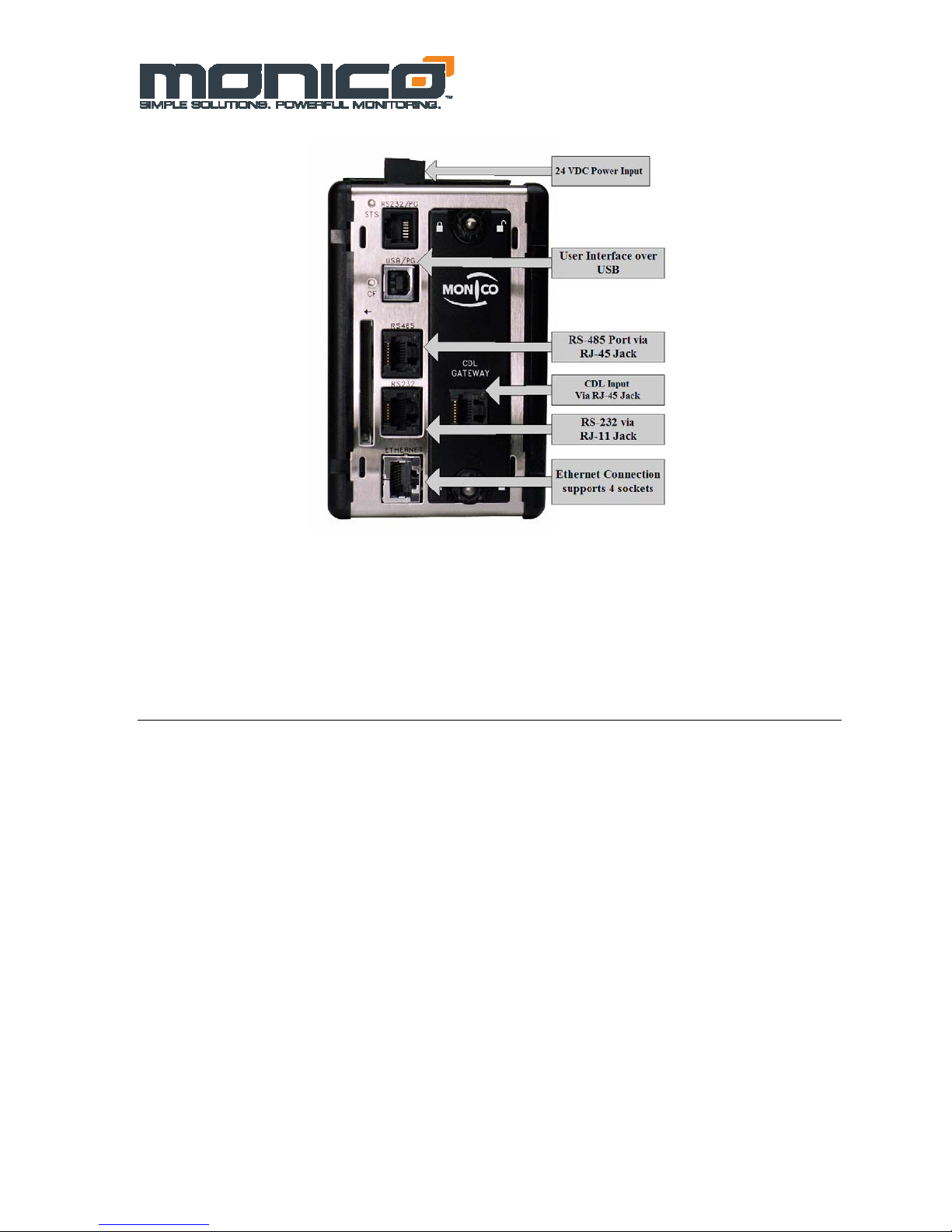
• The CDL Gateway™-Modbus Version offers Modbus RTU over Serial RS-232 and RS-485 as well as
Modbus TCP/IP over Ethernet. All ports are available on the same unit
• The CDL Gateway™ has a User Interface via a USB connection that allows you to configure the ports
and see exactly which parameters are responding on your installation.
• The CDL Gateway™ has an integral 24 VDC Power Supply
• The CDL Gateway™ is designed to be mounted on Din-Rails, so no adapters are needed
• The CDL Gateway™ uses modular jacks for connections which minimizes wiring errors, especially
when using our optional factory cables
• The CDL Gateway™ does not require complicated address offsets.
• The CDL Gateway™ does not require complicated Enable/Disable Masks as all parameters are default
enabled. If necessary, the user can deactivate individual registers or ports via the User Interface, but
due to the drastic increase in speed it should not be necessary for m oni t oring purposes
• The CDL Gateway™ allows for other host protocols such as BACnet and can push parameters directly
to Allen Bradley Data Registers or Controller Tags, GE Fanuc Analog Input Registers, and Siemens
Data Blocks via RS-232, RS-485, and Ethernet. Special instructions for these versions are covered in
the appendix sections of this manual.
an engine controller and is only used for monitoring engine and
- 3 -
v1.05
6.26.09
Figure 1.0 Gateway Connections Overview
Section 1: Power Supply
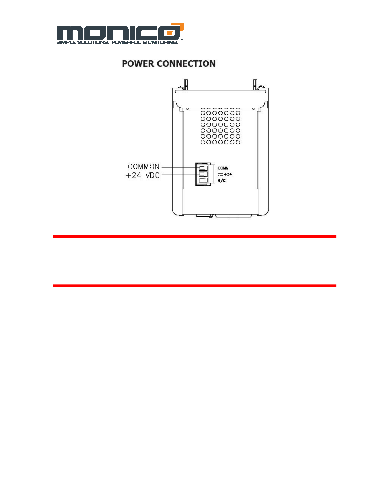
The CDL Gateway™ requires regulated 24 Vdc +/- 10% with 1000 ma power maximum.
Must use Class 2 or SELV rated power supply. You may use either an Isolated power
supply, or the properly grounded engine batteries to power the Gateway. If using an
isolated power supply, make sure to use CDL Monitor 2.0. If power is applied, the green
STS light will function. If this light is blinking, then no setup file is installed or it is
currently loading a file. If this light is solid, then a setup file is resident and operating.
- 4 -
v1.05
6.26.09
CAUTION
Reversing wire polarity may cause damage to your Gateway. This damage is not
covered by warranty. If in doubt about which wire is which on your power supply,
check with a meter.
If you must use an external power supply, it is very important that the power supply is mounted
correctly if the unit is to operate reliably. Please take care to observe the following points:
– The power supply must be mounted close to the unit, with usually not more than 6 feet (1.8
m) of cable between the supply and the Gateway. Ideally, the shortest length possible should
be used. The wire used to connect the Gateway’s power supply should be at least 22-gage
wire. If a longer cable run is used, a heavier gage wire should be used. The routing of the
cable should be kept away from large contactors, inverters, and other devices which may
generate significant electrical noise.
– A power supply with a Class 2 or SELV rating is to be used. A Class 2 or SELV power
supply provides isolation to accessible circuits from hazardous voltage levels generated by a
mains power supply due to single faults. SELV is an acronym for “safety extra-low voltage.”
Safety extra low voltage circuits shall exhibit voltages safe to touch both under normal
operating conditions and after a single fault, such as a breakdown of a layer of basic
insulation or after the failure of a single component has occurred.
- 5 -

v1.05
6.26.09
EMC INSTALLATION GUIDELINES
Although the CDL Gateway™ is designed with a high degree of immunity to Electromagnetic Interference
(EMI), proper installation and wiring methods must be followed to ensure compatibility in each ap plication.
The type of electrical noise, source or coupling method into a unit may be different for various installations.
Cable length, routing, and shield termination are very important and can mean the difference between a
successful or troublesome installation. Listed are some EMI guidelines for a successful installation in an
industrial environment.
1. To reduce the chance of noise spikes entering the unit via the power lines, connections should be made to a
clean source. Connecting to circuits that also power loads such as contactors, relays, motors, solenoids etc.
should be avoided.
2. The unit should be mounted in a metal enclosure, which is properly connected to protective earth.
3. Use shielded (screened) cables for all Signal and Control inputs. The shield (screen) pigtail connection should
be made as short as possible. The connection point for the shield depends somewhat upon the application.
Listed below are the recommended methods of connecting the shield, in order of their effectiveness.
a. Connect the shield to earth ground (protective earth) at one end where the unit is mounted.
b. Connect the shield to earth ground at both ends of the cable, usually when the noise source
frequency is over 1 MHz.
c. Connect the shield to common of the Data Station and leave the other end of the shield unconnected
and insulated from earth ground.
4. Never run Signal or Control cables in the same conduit or raceway with AC power lines, conductors feeding
motors, solenoids, SCR controls, and heaters, etc. The cables should be run through metal conduit that is
properly grounded. This is especially useful in applications where cable runs are long and portable two-way
radios are used in close proximity or if the installation is near a commercial radio transmitter. Also, Signal or
Control cables within an enclosure should be routed as far away as possible from contactors, control relays,
transformers, and other noisy components.
5. Long cable runs are more susceptible to EMI pickup than short cable runs. Therefore, keep cable runs as
short as possible.
6. In extremely high EMI environments, the use of external EMI suppression devices is effective. The following
EMI suppression devices (or equivalent) are recommended:
Ferrite Suppression Cores for signal and control cables:
Fair-Rite part number 0443167251 (RLC part number FCOR0000)
TDK part number ZCAT3035-1330A
Steward part number 28B2029-0A0
Line Filters for input power cables:
Schaffner part number FN610-1/07 (RLC part number LFIL0000)
Schaffner part number FN670-1.8/07
Corcom part number 1 VR3
SPECIFICATIONS
1. POWER: 24 VDC ± 10%
200 mA min., without expansion card
1 Amp maximum with expansion card fitted
Must use Class 2 or SELV rated power supply.
2. COMMUNICATIONS:
USB/PG Port: Adheres to USB specification 1.1. Device only using Type B
connection.
Serial Ports: Format and Baud Rates for each port are individually software
programmable up to 115,200 baud.
RS232/PG Port: RS232 port via RJ12
COMMS Ports: RS422/485 port via RJ45, and RS232 port via RJ12
DH485 TXEN: Transmit enable; open collector, V
OL = 0.5 V @ 25 mA max.
V
Ethernet Port: 10 BASE-T / 100 BASE-TX
RJ45 jack is wired as a NIC (Network Interface Card).
3. LEDs:
STS – Status LED indicates condition of Data Station.
TX/RX – Transmit/Receive LEDs show serial activity.
Ethernet – Link and activity LEDs.
OH = 15 VDC,
- 6 -

CF – CompactFlash LED indicates card status and read/write activity
4. MEMORY:
On-board User Memory: 4 Mbytes of non-volatile Flash memory.
On-board SDRAM:
DSPSX: 2 Mbytes
DSPGT: 8 Mbytes
Memory Card: CompactFlash Type II slot for Type I and Type II cards.
5. REAL-TIME CLOCK: Typical accuracy is less than one minute per month
drift. Crimson 2.0’s SNTP facility allows synchronization with external servers.
Battery: Lithium Coin Cell. Typical lifetime of 10 years at 25 ºC.
A “Battery Low” system variable is available so that the programmer can
choose specific action(s) to occur when the battery voltage drops below
its nominal voltage.
6. ENVIRONMENTAL CONDITIONS:
Operating Temperature Range: 0 to 50°C
Storage Temperature Range: -30 to +70°C
Operating and Storage Humidity: 80% max relative humidity,
non-condensing, from 0 to 50°C
Vibration According to IEC 68-2-6: 5 to 150 Hz, in X, Y, Z direction for 1.5
hours, 2 g’s.
Shock According to IEC 68-2-27: Operational 30 g, 11 msec in 3 directions.
Altitude: Up to 2000 meters
7. CONSTRUCTION: Case body is burgundy high impact plastic and
stainless steel. Installation Category I, Pollution Degree 2.
8. POWER CONNECTION: Removable wire clamp screw terminal block.
Wire Gage Capacity: 24 AWG to 12 AWG
Torque: 4.45 to 5.34 in/lb (0.5 to 0.6 N-m)
9. MOUNTING: Snaps onto standard DIN style top hat (T) profile mounting
rails according to EN50022 -35 x 7.5 and -35 x 15.
10. CERTIFICATIONS AND COMPLIANCES:
SAFETY
C-UL Class I Division II Groups A-D Approved for Hazardous Locations
UL Listed, File #E317425, ANSI/ISA12.12.01-2007, CSA22.2 No. 213-M1987
LISTED by Und. Lab. Inc. to U.S. and Canadian safety standards
UL Listed, File #E302106, UL508, CSA 22.2 No. 14-M05
LISTED by Und. Lab. Inc. to U.S. and Canadian safety standards
IEC 61010-1, EN 61010-1: Safety requirements for electrical equipment for
measurement, control, and laboratory use, Part 1.
ELECTROMAGNETIC COMPATIBILITY
Emissions and Immunity to EN 61326: Electrical Equipment for
Measurement, Control and Laboratory use.
Notes:
1. Criterion A: Normal operation within specified limits.
2. This device was designed for installation in an enclosure. To avoid
electrostatic discharge to the unit in environments with static levels above
4 kV precautions should be taken when the device is mounted outside an
enclosure. When working in an enclosure (ex. making adjustments, setting
jumpers etc.) typical anti-static precautions should be observed before
touching the unit.
11. WEIGHT: 15.1 oz (456.4 g)
Immunity to Industrial Locations:
Electrostatic discharge EN 61000-4-2 Criterion A
4 kV contact discharge
8 kV air discharge
Electromagnetic RF fields EN 61000-4-3 Criterion A
10 V/m
Fast transients (burst) EN 61000-4-4 Criterion A
2 kV power
2 kV signal
Surge EN 61000-4-5 Criterion A
1kV L-L,2 kV L&N-E power
RF conducted interference EN 61000-4-6 Criterion A
3 V/rms
Emissions:
Emissions EN 55011 Class A
2
v1.05
6.26.09
- 7 -
Section 2: Hardware Installation
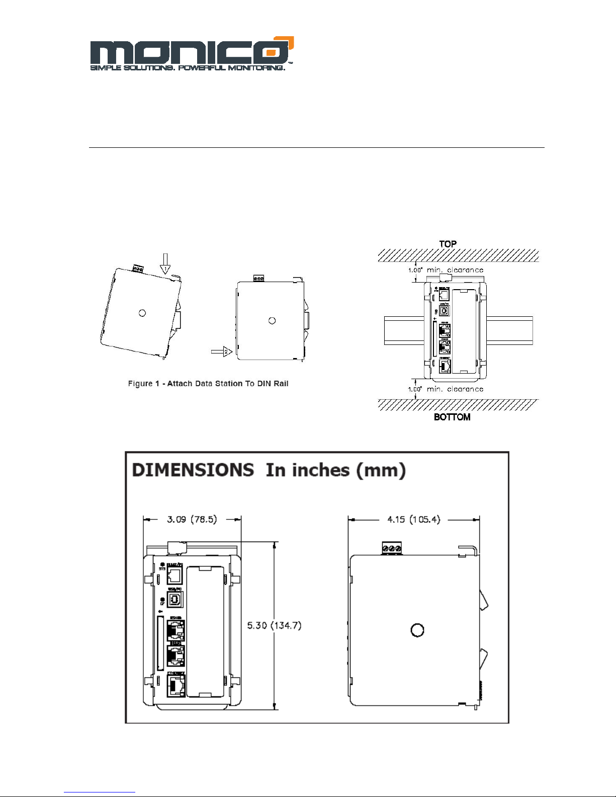
DIN rail should be mounted horizontally so that the unit’s ventilation holes
are vertical in relation to cabinet orientation. A minimum clearance of 1 inch
(25.4 mm) should be maintained above and below the unit in order to ensure
proper thermal regulation.
v1.05
6.26.09
Figure 2.1 Hardware Installation
- 8 -
Figure 2.2 Hardware Dimensions
v1.05
6.26.09
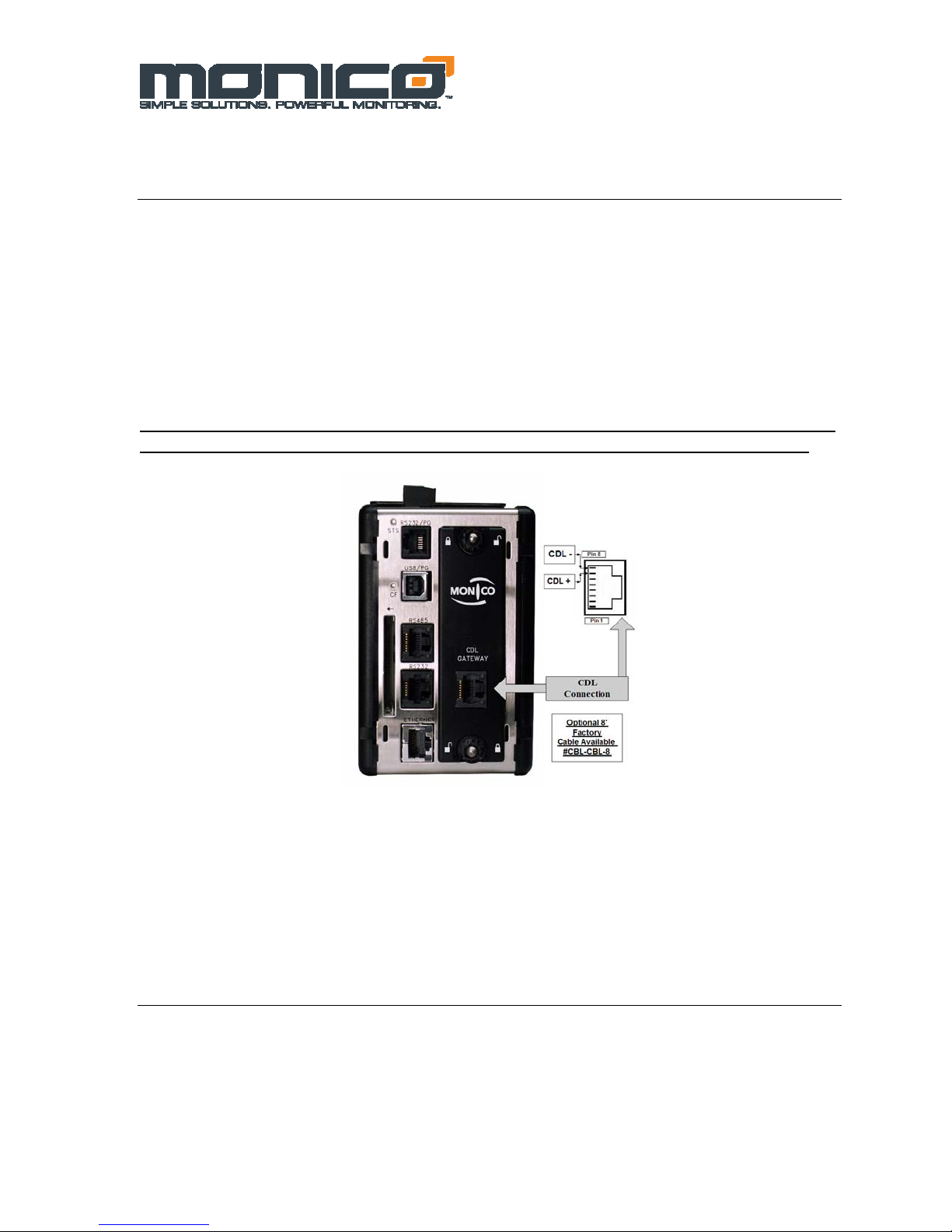
Section 3: CDL Connection to the Engine
Connection to the Data Link is via the RJ-45 Jack (Figure 3.1). The CDL is a differential
buss that is relatively noise immune, but care must be taken not to create ground loops and
good wiring practices are critical. This RJ-45 port has built-in receive (Rx-red) and transmit
(Tx-Green) LED lights which will show transmit and receive activity. If there is no action
with these lights after 5-10 seconds, then the Data Link is not active or not present. Please
note that the Caterpillar panel must be powered on for the data link to be active. If the Rx
light is on solid, then the CDL connections are reversed or the cable length is too long. If the
cable is too long, you may need to add a resistor across the terminals on the CDL Gateway™
side of the connection to lower the cable impedance. Before trying this, consult the factory.
Be sure the Gateway is powered using and isolated 24 VDC source and the EMC wiring
guidelines listed in Section 1 are followed or the properly grounded engine batteries.
Figure 3.1 CDL Connection Pin #7=CDL (+); Pin# 8=C D L (-)
Section 4: CDL Gateway™ Host Connections
The Host device (PLC, HMI, Building Management System, etc.) is connected to the
Gateway through one of three host ports. The Gateway offers one RS 232 port (RJ-11 Jack);
one RS-485 port (RJ-45 Jack) and one Ethernet Port (RJ-45 Jack-Shielded).
- 9 -
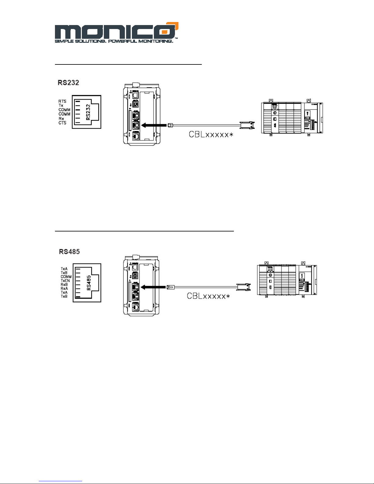
Host Connection-RS-232 via RJ-11 Jack
v1.05
6.26.09
Figure 4.2 RS-232 Connections
Host Connections-RS-485/RS-422 via RJ-45 Jack
Figure 4.3 RS-485/RS-422 Connections
- 10 -

Figure 4.3 RS-485/RS-422 Schematic
Please note that different companies use different terminology. For example, some use TxA and TxB to
describe 2- wire RS-485 connections. Some use Tx+ and Tx-. In general. TxA=Tx- and TxB=Tx+
For 2-wire RS-485, use Pin#7 = (+) and Pin#8 = (-).
Host Connections-TCP/IP over Ethernet via RJ-45 Shielded Jack
Ethernet
v1.05
6.26.09
ETHERNET COMMUNICATIONS
Ethernet communications can be established at either 10 BASE-T or 100 BASE-TX. The
Gateway’s RJ45 jack (Figure 4.4) is wired as a NIC (Network Interface Card). For example,
when wiring to a hub or switch use a straight-through cable, but when connecting to another
NIC use a crossover cable. Default IP Address is 192.168.1.10
- 11 -
Figure 4.4 Ethernet Connections

v1.05
6.26.09
Section 5: Troubleshooting LED’s
STS – STATUS LED
The green Status LED provides information regarding the state of the Gateway. This includes
indication of the various stages of the start-up routine (power-up), and any errors that may
occur.
Startup Routine
Indication
LED
Rapidly Flashing Gateway is currently loading program
Steady Gateway is operating normally
Table 5.1 STS LED
SERIAL HOST PORTS - TX/RX LED’S
LED
Indication
Green Transmitting
Red Receiving
CDL PORT - TX/RX LED’S
LED Indication
Green Transmitting
Red Receiving
TCP/IP ETHERNET PORT LED’S
LED Indication
Yellow (Solid) Link Established
Yellow (Flashing) Network Activity
Green 10 BASE-T Communications
Amber 100 BASE-T Communications
These LED’s are the first step in troubleshooting communications issues. Please note
the action of these LED’s, IN DETAIL, when contacting the factory for technical
support.
Table 5.2 Serial Host Port LED’s
Table 5.3 CDL Port LED’s
Table 5.4 Ethernet Port LED’s
- 12 -

v1.05
6.26.09
Section 6: MonicoView Programmer
The MonicoView Programmer is a critical part of the product. This free software is used to
develop programs or modify files supplied from the factory to meet your needs. Please check
on our website for the latest version at www.monicoinc.com
port settings for each available port, to disable unused ports to maximize performance, to
delete unused or unavailable parameters from polling blocks, and to view live data for all
data blocks. MonicoView can also be used to modify any section of the unit programming.
However, make sure to use LINK-EXTRACT to save a copy of the original .mvd program
before making changes. If you click on the UPDATE button before OPENING a valid file
or EXTRACTING the existing file, it will result in a blank file being downloaded to the
Gateway which will render it ineffective. If this should occur, contact the factory and we can
email a copy of the file supplied with the Gateway. Please make note of the Version Number
on the label on the right side of the Gateway, so we can identify the appropriate file.
When upgrading MonicoView Programmers versions, us the REPAIR option.
The connection is established through a standard USB device cable that has the rectangular
connector on one end and the square connector with two rounded edges on the other. Make
sure to click on LINK-OPTIONS and set the connection to USB.
Installing USB Drivers
In some cases, connecting a laptop to AC can cause electrical grounding issues. In some
situations, a grounded AC supply on a laptop can cause intermittent errors with the laptop
USB port. Each time you connect, using the MonicoView Software, to a new CDL Gateway
unit, you will see the Windows “Found New Hardware” screen. Make sure to plug in the
USB Cable when the Gateway is powered down. Upon power up, it will then ask for both
required drivers to be installed at once.
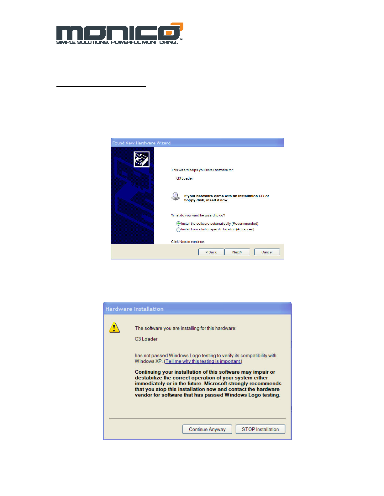
First Installation
The first installation of the USB drivers from a specific computer will have to be done
manually. After this first installation on a given PC, it will know where to look for the
appropriate files. When asked to go to Windows Update to find a driver, select “No, not at
this time” and click “Next”. This will bring up the screen shown in Figure 6.1 below and the
“Install Automatically” should be selected by default. INSTEAD, choose Install From List
or Specific Location, click NEXT and use the Browse button to select the following location:
C:\Program Files\Monico\Monicoview\Device
Click Next and follow the instructions below to finish the process. From this point on, you
can use the Automatic Install option which is much simpler.
. MonicoView is used to adjust
- 13 -
v1.05
6.26.09
Subsequent Installations
When asked to go to Windows Update to find a driver, select “No, not at this time” and click
“Next”. This will bring up the screen shown in Figure 6.1 below and the “Install
Automatically” should be selected by default. If your first installation is not successful, you
will need to follow the instructions at the end of this section to navigate to Device Manager
and perform a manual install.
Figure 6.1: USB Driver Automatic Installation
After this screen you will see the screen below stating that the driver you are installing has
not been tested by Microsoft. Select “Continue Anyway”.
Figure 6.2: Windows Compatibility Warning
- 14 -
 Loading...