

Page 1
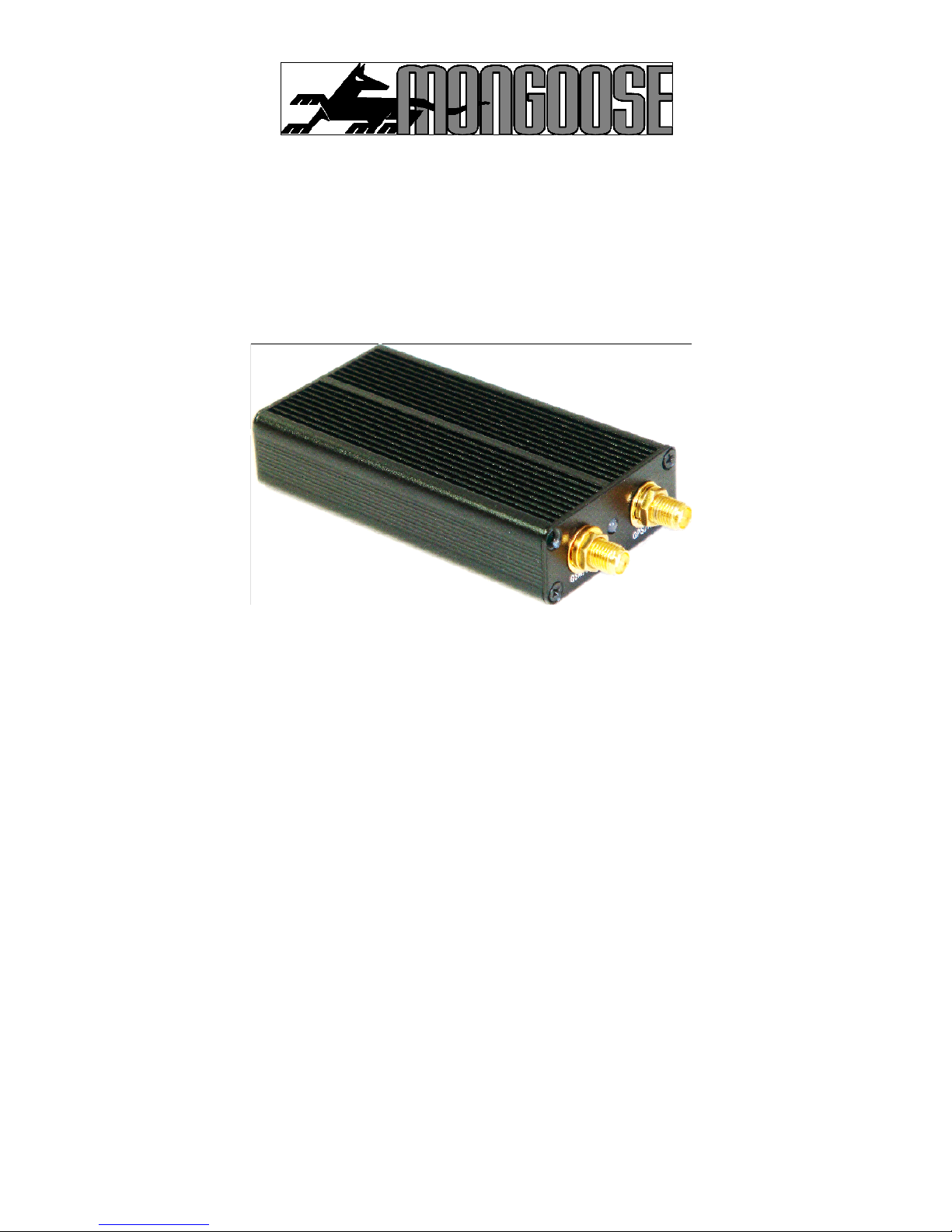
MONGOOSE VT401
GPS VEHICLE TRACKER
User Manual
The VT401 is a wired vehicle GPS tracker using satellites to calculate its precise
location and both GSM and GPRS technology for communications.
It may be used with any +12 volt DC power s
upply, negative ground application.
A GSM SMS mobile phone, not supplied, is required to communicate and control this
tracker.
The tracker transmits its latitude and longitude coordinates only to authorized mobile
phone numbers of your choice or via GPRS t
o a computer.
For GPRS communications, please refer to the separate manual.
Mongoose Australia PTY Limited
www.mongoose.com.au
Mongoose (New Zealand) Limited
www.mongoose.co.nz
The information contained in this manual was correct at time of publ
ication.
Please visit our website for any updates of this manual.
Page 2

2
Thankyou for purchasing this
Mongoose
GPS vehicle tracker.
Please read this manual carefully before using this product.
Keep this manual handy for future reference.
Contents
Quick &
Easy start
-
up / Mapping
-------------------
3
Setting user phone numbers
-------------------------
4
Password
---------------------------------------------------
4
Manual tracking
------------------------------------------
5
Automatic tracking
-------
--------------------------------
5
Cancel automatic tracking
----------------------------
5
Geo
-
Fence / SOS
---------------------------------------
6
Ring alert
---------------------------------------------------
7
Car alarm alert
-----------------
---------------------------
7
Adjusting time for daylight saving
-----------------
7
Immobilise the engine
----------------------------------
8
Power saver
-----------------------------------------------
9
Vibration sensor
-----------------------------
--------------
9
SMS mode
--------------------------------------------------
9
Low voltage / Cautions
----------------------------------
13
Installation
---------------------------------------------------
11/12/13
Specifications
--------------
--------------------------------
13
NOTES:
Use of this product or certain features may infringe the rights or invade the privacy of
others depending on local or countrylaw.
The use of mobile GSM transmitting/receiving devices, such as this GPS tracke
r, may be
restricted in certain locations, especially aircraft. Itis your responsibility to ensure correct
and permitted usage.
Mongoose is not responsible for the non
-
operation of this product should GPS or GSM
signals not be available or be able to be
received.
Page 3

3
4 QUICK & EASY START
-
UP STEPS
1.
Insert the SIM card, theninstall the tracker into the vehicle (see page 11) .
2.
Send
the text command 7000000 Thi
s confirms SMS mode
& operation
3.
Set your mobile phone as the main USER by sending the following textcommand from
your mobile phoneto the tracker;
Text mu
st be in this format:
-*phone number
*
password
*
user number
**
(must use
*
as separators
-
factory default password is 0000)
Eg:
*
yourphonenumber
*
0000
*1**
Tracker replies by
SMS
text with
‘SET USER NUMBER #
OK’
4.
Find the trackers map co
-
ordinates location
-
send the following text command;
888 (Function) + password(0000)
Example:
8880000
The tracker will reply by text message with its latitude & longitudelocation.
MAPPING
No mapping software is supplied or required to be purchased as freely available mapping
is available on the internet on websites such as Google Maps/Earth.
Other equi
pment may also be used such as GPS navigators, PDA’s, internet capable
mobile phones and laptop computers.
The information sent from the tracker to
a
mobile phone will look like this;
Lat
36.831546S
Long
174.745789E
Speed
80.00KM/H
Direction
168.00
(degrees)
Date
25/12/10
Time
10:22:00
Fix
A/V
ID
1357900000000
STATE:
*****
By
using one of the Google websites, simply type in the latitude and longitude in this
format;
It is important to include the ‘
S
’ and the ‘
E
’–leave a space betwe
en co
-
ordinates.
36.831546S 174.745789E
GPS location is then displayed (the above location is Auckland’s harbour bridge)
Page 4
4
USERS
-
SETTING THE MAIN PHONE NUMBERS (maximum 3)
Up to three mobile phones can communicate with this GPS tracker.
If ‘users’ are no
t programmed, the tracker will not operate correctly.
T
he ‘user number’ sets priority. ‘1’ is main user.
If the SOS function is used, the sequence is 1, 2 then 3
–
so set the following carefully in
the order you require.
IMPORTANT:
Do not hide the ‘ident
ity’ of your mobile phone, or any ‘user’, as
the track
er needs to identifythe caller soit can respond.
The format is:
-
*phone number(max’ 20 numbers)*password* user number**
USER
number
Example
Reply
1
*0211234567*0000*1**
CONFIG OK
2
*027999
4321*0000*2**
CHANGE OK
3
*0212223322*0000*3**
CHANGE OK
To change one of the users, simply re
-
send the command for the user being
changed.
PASSWORD
A password is used in all SMS text commands and is composed of 4 numbers.
The factory default pas
sword is “
0000
”.
The password should only be changed to prevent others from using the tracker if it gets
lost or is stolen.
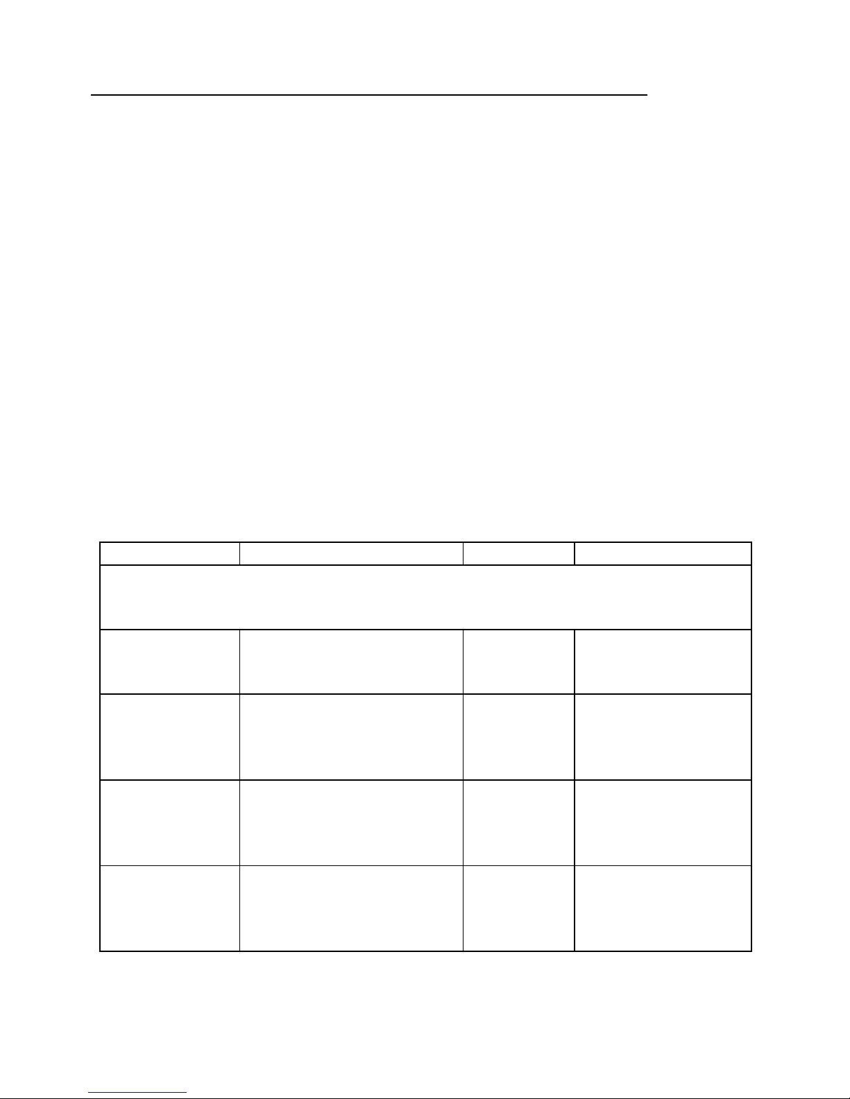
Feature
Format of text command
Example
Reply
Change
password
777 + New Password +
Old Password
777
12340000
CHANGE
OK
The old password is now replaced
–
write it down or record it in your mobile phone.
All text commands now use your password, not ‘0000’.
DO NOT CHANGE THE PASSWORD IF THE GPRS MODE IS USED.
Page 5
5
MANUAL TRACKING
–
REQUEST CURRENT LOCATION
You can manually request the current location of the tracker 2 ways;
a.
By voice calling
b.
By SMS text message
a. Voice calling for location
Any of the three ‘user’ phone numbers can call the tracker to request its location.
Dial the phone number of the tr
acker
–
it automatically hangs up after 3
-
4
rings.
The tracker will reply by text message with its latitude & longitude location.
b. SMS text for location
Feature
Format of text command
Example
Reply
Request location
by text message
888 + Password
88
80000
LOCATION
DETAILS
AUTOMATIC TRACKING
–
GET LOCATION AT PROGRAMMED TIME
INTERVALS
You can programme the tracker to automatically report its position at time intervals of
your choice. Reporting time is either minutes or whole hours.
Minute time ran
ge is 01
-
60 (00 = OFF)
Hour(s) time range is 62~99 62 = 2 hours ~ 99 = 39 hours
Cancel Auto tracking
Automatic tracking will continue until the tracker receives the ‘cancel’ command.
Please note that text messages from the tracker incur SIM card costs.
Feature
For
mat of text command
Example
Reply
Cancel
a
utomatic
tracking
400
+ Password
400
0000
TIMER
STOP
Feature
Format of text
command
Example
Reply
Request
location by
automatic
tracking
4 xx (xx = time in
minutes) +
Password
4100000
(every 10 mins)
4620000
(every 2 hours)
TIME
R START,
REPEAT
INTERVAL:
XX MINUTES
Page 6
6
GEO
-
FENCE
–
restricting area of travel
You can restrict travel towithin a certain area bysetting a ‘geo
-
fence’.
A geo
-
fence is defined bya centre
-point (where it currently is) with a permitted radius of travel
from that centre
-
point.
This can be from a
recommended
minimum of 1
kilometre
to a
maximum of 1000 kilometres (
999.9
).
If the tracker moves outsidethis permitted area, it will make a telephone
call as an alert to the
mobile phone thatset the geo
-
fence. It will also send a text alert with its location and includes
‘STATE: OS’ to show the geo
-
fence area has been exceeded.
The tracker will repeat the above when the tracker re
-
enters the geo
-
fen
ced
area.
,
‘STATE:RS’ will show on the text message
To use geo
-
fence;
1.
Set the geo
-
fence area
2.
Turn geo
-
fence ON
3.
Turn geo
-
fence OFF
Feature
Format of text
command
Example
Reply
Set
Geo
-
fence
005+Password+Radius
0050000R10.0
(10km)
Contains co
-
ordinat
es of
centre point
Turn
Geo
-
fence
ON
211 + Password
2110000
GEO
-
FENCE
ON
Turn
Geo
-
fence
OFF
210 + Password
2100000
GEO
-
FENCE
OFF
(Radius is from 1.0 to 999.9)
Radius of less than 1 km, such
as 0.
5(5
00 metres) can be set but may not be accurate
SOS
–
HELP REQUEST
Press the SOS button for more than 10 seconds.
The tracker will make a telephone call alert* to the first user telephone
number
–
this is an audible alert only, no voice communica
tion is possible.
It will send then its location, including ‘SOS’, to all stored users.
Note:
If the ‘telephone call alert’ is off, it will not make a telephone call and only send text
alert messages.
* The tracker cannot be used as a telephone as it do
es not contain a microphone or
speaker. The telephone ring is an alert only.
Page 7

7
TELEPHONE RING ALERT
-
TRACKER TO MOBILE PHONE
(DEFAULT ON)
If the alarm/SOS function is used or the vehicle travels out of or into a geo
-
fence area, the
tracker will send an al
ert by making a normal telephone call to the users mobile phone as
well as sending a text message withits location.
No voice communication is possible with this product
–
the call is an audible alert only.
Telephone call alerts can be programmed off but
SMS text alerts will still be sent.
Feature
Format of text command
Example
Reply
Telephone
calling OFF
150+ Password
1500000
SET VOICE
CALL:OFF
Telephone
calling ON
(default)
151+ Password
1510000
SET VOICE
CALL:ON
CAR ALARM ACTIVATION ALERT (O
PTIONAL)
The tracker can be connected to a vehicles car security system
s
siren to provide a text
warning if the alarm is activated.
Any sounding of the alarms siren longer than 10 seconds will activate the SOS function
above
-
the
alert message is the sam
e as SOS.
Normal
chirps for the
alarm
s
arm, disarm and pre
-
intrusion should not cause an alert
unless longer than 10 seconds
-
depends on the make and model of alarm.
NOTE:
This feature may not be compatible with all car alarm systems.
Please advise al
l ‘users’ the meaning of the SOS alert as it may be an alarm
activation or a call for help or assistance.
ADJUSTING TIME (DAYLIGHT SAVINGS)
The time on received messages from the tracker can be adjusted to allow
for
worldwide usage and
daylight savings.
Feature
Format of text command
Example
Reply
Adjusting
the clock
896
+ Password +
E/W
hours
based on
GMT
8960000W
12
TIME
SET: OK
‘E’ time behind GMT
‘W’ time ahead of GMT
(Australia/NZ uses ‘W’ plus hours ahead of GMT)
Page 8
8
IMMOBILISE THE ENGINE
(opti
onal fitment
-
may require additional parts/labour)
The tracker provides you with the ability to immobilise a vehicles engine independently of
any other security system or device.
Only use this feature it is known that the vehicle is not moving. This can
be established
from received GPS data which shows vehicle speed. Safety consideration of all person
s
and propertyis paramount.
Our recommendation is immobilisation of the starter motor
only
which will prevent engine
starting next time
the vehicleis used
and does not affect current running condition
.
The use of this feature may not be permitted in some countries or states and use is
therefore at the owners discretion.
The installer of this product has the right to refuse connection/use of this feature if
prohibited by law or considers it not suitable for the intended purpose.
Mongoose accepts no responsibility for unlawful, incorrect or inappropriate usage or
fitment.
(This feature can be used for other purposes as the output of the tracker is a text
con
trolled ‘ground’ output for ON & OFF)
Engine immobilisation is not immediate, it requires confirmation before the initial
command is executed.
Feature
Format of text command
Example
Reply
Confirmation required to execute th
is
command
Immobilise
900
+ Password
9000000
CONFIRM
POWER OFF?
Confirm
command
901 + Password
9010000
POWER OFF: OK
(engine immobilised)
Cancel
immobilisation
902 + Password
9020000
CONFIRM
POWER ON?
Confirm
command
903 + Password
9030000
POWER ON: OK
(engine not
immobi
lised)
Page 9

9
POWER SAVER
There may be occasions when your vehicle is not going to be used for some time but
you wish to maintain its batterypower for as long as possible.
You can turn off the GPS reception to preserve batterylife but it will remain connecte
d to
the GSM network so it can receive GSM commands when you wish to turn the GPS
function back on. A built
-
in vibration sensor automatically turns the GPS back on if it
detects sufficient movement (see below).
Feature
Format of text command
Example
Reply
Turn GPS ‘OFF’
333 + Password
333000
GPS OFF OK
Turn GPS ‘ON’
222 + Password
222000
GPS ON OK
VIBRATION SENSOR
The tracker contains a vibration sensor to monitor if the vehicle is moved so it can re
-
establish GPS reception if turned OFF by the pre
vious power saving command.
There is no alarm function associated with this feature.
If sufficient vibration is detected, the tracker will automatically re
-
start the GPS location
function.
If vibration is not excessive, the tracker may not turn back on unt
il a sharp knock is
detected
If no further movement is detected within 5 minutes, GPS will turn off.
Users can send 222 + user passwords to re
-
start the GPS tracking function.
Feature
Format of text command
Example
Reply
Turn vibration
sensor‘ ON’
100 +
Password
1000000
VIBRATION
SENSOR
ON OK
CONFIRMING MODE OF OPERATION (FACTORY DEFAULT = SMS TEXT)
The tracker can communicate its position by either SMS text or direct to a
computer or website via GPRS. This manual is specific to SMS text mode.
Toco
nfirm SMS text mode send the command below.
Feature
Format of text command
Example
Reply
SMS text
mode
700 + Password
7000000
MODE NOT CHANGED,
CURRENT MODE: SMS
P2P
or
SETMODE OK,
CURRENT MODE: SMS
P2P
See separate manual for GPRS mode operatio
n.
Page 10

10
LOW VOLTAGE WARNING
When the trackers nominal working voltage is lower than normal, it will alert all users 3
times at 1 minute intervals before it turns off and becomes inoperable.
The alert will contain location information plus ‘STATE: LP’
-
meaning
low power.
CAUTIONS
1. Keep the unit dry. Any liquid may destroy or damage theinside circuitry.
2. Don’t use or storethe unit in dusty places.
3. Don’t keep the unitin extremes of heat and cold.
4. Handle carefully. Do not drop, vibrate or shake i
t violently.
5. Clean with dry cloth. Don’t clean in chemicals or detergent, etc.
6. Do not disassemble, tamper or attempt any repair.
7. Don’t use other antennas. Thismay interfere with the reception/transmission and may
increase radiation.
8. Tamper
ing, abuse and misuse with the unit will void any warranties.
LED STATE DESCRIPTION
RED LED
—
indicates power state:
State
Meaning
Constant Lighting
Searching for GSM signal
Flash every 8 seconds
GSM reception okay
GREEN LED
—
indicates GPS signal state
:
State
Meaning
Constant Lighting
GPS not located
Flashes steadily
GPS position located
Page 11

11
FAQ’s
Question
Solution
Does not respondto text
commands ortext location
requests
Has the unit been turned ON and battery charged ?
Is the unit in SMS text
mode ?
Has the mobile phone been programmed to the tracker ?
Is the SIM card inserted correctly ?
Is there sufficient SIM card credit ?
Check the phone number of the SIM card
Check text commands areentered correctly
Is the identity of the mobile phone hid
den ?
Start
-
up fail
Has the unit been installed correctly ?
Check LED on unit forsignal reception.
Is the unit indoors ? Try outdoors for a stronger signal.
Check the SIM cardis inserted correctly.
Does not respondto voice calls
Has yourmobile phone
been programmed to the tracker ?
Check the phone number of the SIM card.
Check that the SIM cardis installed correctly.
Is your mobile phone caller ID been turned off ?
Didn’t receive a text reply
GSM network may be busy or overloaded.
Is the unit in SM
S text mode?
SIM card has no credit.
Incorrect text command sent to the tracker
Incorrect SIM number
Location report does not include
data for latitude & longitude.
No GPS reception.
Position request too soon after power
-upIs the vehicle inside a build
ing ?
Move vehicle outside and re
-
request
Any updates to this manual can be found on ourwebsites
Page 12

1213
4
INSTALLATION
Parts included;
1)
GPS vehicle tracker
2)
Wiring harness
3)
Magnetic GPS antenna
4)
On-screen hi
-
gain GSM antenna
5)
This manual
We recommend profes
sional installation of this product to ensure correct connections
and safety and reliability of the this and the vehicle.
Locating the tracker and antennas
Main module
For security reasons, the tracker module should be concealedfrom view to prevent tamp
ering.
Typical locations are behind the glove box, up high behind the dashboard instruments or
behindthecentre console.
Final fitting and location should becompleted once full and correct operation has been verified.
GSM antenna
A flat on
-
glass hi
-
gain
antenna is supplied. Typical location is above the vehicles interior
mirror.
GPS antenna
The GPS antenna must be mounted where it can ‘see’ the skyand not obstructed by metal or
electronic equipment.
The antenna is magnetic to allow it to adhere above mo
st metallic surfaces, otherwise affix
with other methods such as double sidedpads, cable ties or velcro.
Ideally, it should be concealed from view so as not to alert anyone that a GPS tracking device
isfitted. GPStracking devices should be covert, so th
e antenna should be hidden from view.
SOS button
This should be mounted where it can be reached from the drivers seat.
Page 13

13
Insert a SIM Card
(not supplied)
–
ensure no power is connected
Before connecting any power to this tracker, remove the 4 screws at the
antenna end
of the module. Withdraw the printed circuit board from the case. Notice the SIM card
slot. Slide the SIM card fully into the slot noting the correct orientation. Refit the circuit
board and replace the screws.
Wiring connections
Red
-
perman
ent +12V
Black
–
ground (
-)Yellow
–
car alarm & SOS (
-
) (relay required for + positive sirens)
Purple
-
engine immobiliser (
-
) (optional connection
–
relay required)
Connection of the SOS button and vehicles car alarm (if vehicle equipped)
For (+) positive siren connection (Fig A);
Use a suitable
low impedance miniature
relay, not supplied, to convert positive siren
output to negative and connect as shown in the diagram below.
For (
-
) negative siren connection (Fig B);
No relay required, c
onnect siren trigger wire to yellow wire of with a diode in
-
line to
prevent pressing SOS button sounding the siren.
Fig A
Fig B
Note: Alarm feature i
noperative from a pulsed horn honk
-
input must be constant ground
for 10 seconds.
ENGINE IMMOBILISER RELAY
(NOT SUPPLIED)
(-) Purple
888387
+12V
LOW CURRENT STARTER
CUT
Page 14

14
SIGNAL STRENGTH
–
GSM & GPS
For greater accuracy and reliable operation, this tracking device should only be used outdoors
to enable it to receive GPS transmissions from m
ultiple satellites.
Operation inside warehouses, workshops, garages, parking buildings, etc, or any other
shielded location that prevents the tracker from receiving satellite information may result in
non
-
operation or inaccurate co
-
ordinates. The more sat
ellites it can receive
-
the more
accuratethe location.Heavy overcastweather will affect GPS signals and accuracy.
This tracker requires connectionto the GSM network to enable 2 waycommunication with
your mobile phone. Signalstrength for certain loca
tions can be checked on your mobile
phones meter.
TRACKING
No software to purchase
-
use freeGoogle Maps / Earth from any computer.
Can also be tracked on mobile equipment such as GPS navigation units, PDA’s, laptops or
internet capablemobile phones..
See our Mongoose website for other mapping options including GPRS.
Specifications
GSM module
MTK program, GSM 900/1800/850/1900
quad
-
band.
Chipset, Sensitivity,
SIRF
-
Star III chipset
-
159dBm L1,1575.42MHz
C/A Code
1.023MHz chip rate
Channels
20 channel all
-in-
view tracking
Position & Velocity Accuracy
10 meters, 2D RMS 0.1 m/s
Time Accuracy
1 us synchronized to GPS time
Datum
WGS
-84Reacquisition
0.1 sec average
Hot start
-
Warm start
-
Cold
1.0 sec average 3.8 sec average 42 sec average
Altitude Limit
18,000 meters (60,000feet) max.
Velocity limit
515 meters/second (1 000knots)max.
Acceleration Limit
Less than4g
Jerk Limit
20m/sec
Operating temperature
-
25℃to 70
℃
Humidity
5%
to 95% Non
-
condensing
Dimension
95m m *46m m * 18mm
Voltage
1 2VDC
–
negative ground
Page 15

15
NOTES
Page 16

16
Mongoose
Australia
Web site: www.mongoose.com.au
NEW SOUTH WALES
Head Office: 6 Hornsby Street, Hornsby
NSW 2147
Ph: (02) 9482 4444
Fax: (02) 9476 8279
Email: sales@mongoose.com.au
QUEENSLAND
Unit8, 871 Boundary Road,
Coopers Plain, Brisbane,
Queensland 4108
Ph: (07) 3344 7611
Fax: (07) 3344 7911
Email: sales@mongoose.com.au
Mongoose
New Zealand
Web site: www.mongoose.co.nz
41A View Road, Glenfield, Auckland
PO Box 101
-
599 NSMC
Ph: (09) 443 3128
Fax: (09) 443 3129
Email: sales@mongoose
.co.nz
 Loading...