

Page 1
PH Gas Logs
INSTALLATION
BEFORE FULLY INSTALLING THE UNIT:
Turn OFF the gas supply to the replace or re-
•
box.
• Seal any fresh air vents and/or ash clean-out doors
located on the oor or wall of the replace. If left
unsealed, drafting may cause pilot outage or soot-
ing. Use a heat resistant sealant. Do not seal the
chimney ue damper.
Before installing in a solid fuel burning
fireplace, The chimney flue and firebox
must be cleaned of soot, creosote, ashes
and loose paint by a qualified chimney
WARNING
cleaner.
INSTALLING VENTED APPLICATIONS
Manual and millivolt controlled gas logs may be installed as
a vented decorative log set in compliance with ANSI Z21.60
and National Fuel Gas Code, Section 6.6 Since, the gas
logs are operated with the damper open, non-combustible
material and minimum mantel requirements do not apply.
NOTE: The use of a thermostat is prohibited in vented log
applications.
This appliance is for installation only in a solid
fuel burning replace (masonry replace or
manufactured fireplace) with a working
ue and constructed of noncombustible
material.
Exception: DO NOT install this appliance
in a factory-built fireplace that includes
WARNING
instructions stating that it has not been
tested or should not be used with unvented
gas logs. This log set may be installed as a
vented log set.
BEFORE INSTALLING THE APPLIANCE:
• Turn off gas supply to replace or rebox.
• Have the replace oor and chimney professionally
cleaned to remove ashes, soot, creosote or other
obstructions. Have this cleaning performed annually
after installation.
• Seal any fresh air vents or ash clean-out doors lo-
cated on oor or wall of replace. If not, drafting may
cause pilot outage or sooting. Use a heat-resistant
sealant. Do not seal chimney ue damper.
Install and operate the appliance as directed in this
manual.
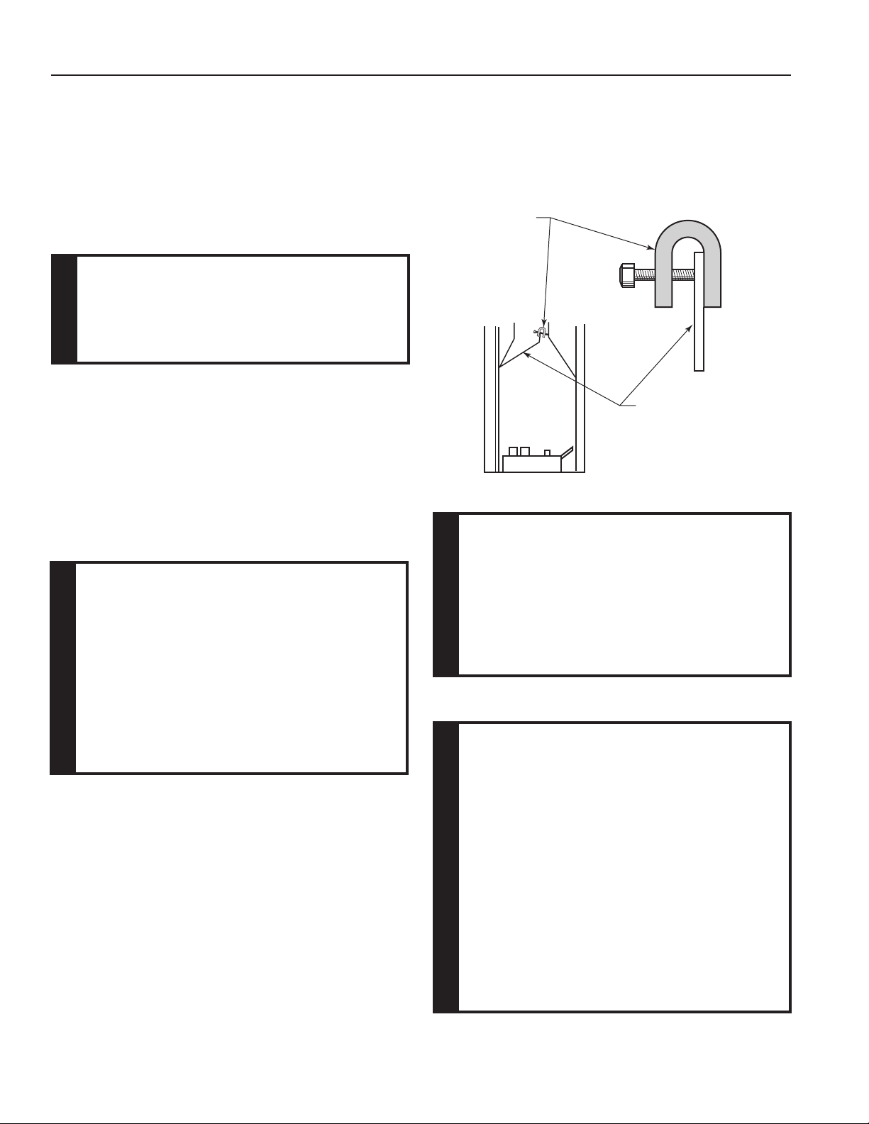
DAMPER STOP INSTALLATION:
A damper stop must be provided with the unit. Contact your
dealer to obtain one. The damper stop must be installed as
shown in Figure 11 to prevent full closure of the replace
damper blade and provide a minimum 29 square inch ue
opening.
Damper
Stop
Damper
FP2538
Figure 11 Damper Stop Installation
(See Warning)
The replace and gas logs function as a
system. If the replace is spilling into the
room (check with a match or a smoke stick),
reposition the damper clamp until a positive
draft is obtained by opening the damper. If
negative pressure in home prevents having
WARNING
a positive draft, contact your dealer for
assistance.
PLACE AND SECURE APPLIANCE
You must secure the gas log heater to
the replace oor. If not, the entire unit
may move when you adjust the controls.
Movement of unit may cause shifting of
the gas logs which leads to sooting and
improper burning.
Special care is required if you are installing
the unit into a sunken replace. You must
raise the replace oor to allow access to
WARNING
gas log controls. This will insure adequate
air ow and guard against sooting. Raise
the replace oor using noncombustible
materials, as described in Placement in a
Fireplace with Restrictive Barrier on Page
7.
12
Monessen • PH18/24 Installation/Owner's Manual • 65D2035 • Rev E • 01/19
Page 2
INSTALLATION
PH Gas Logs
ASSEMBLY PROCEDURE
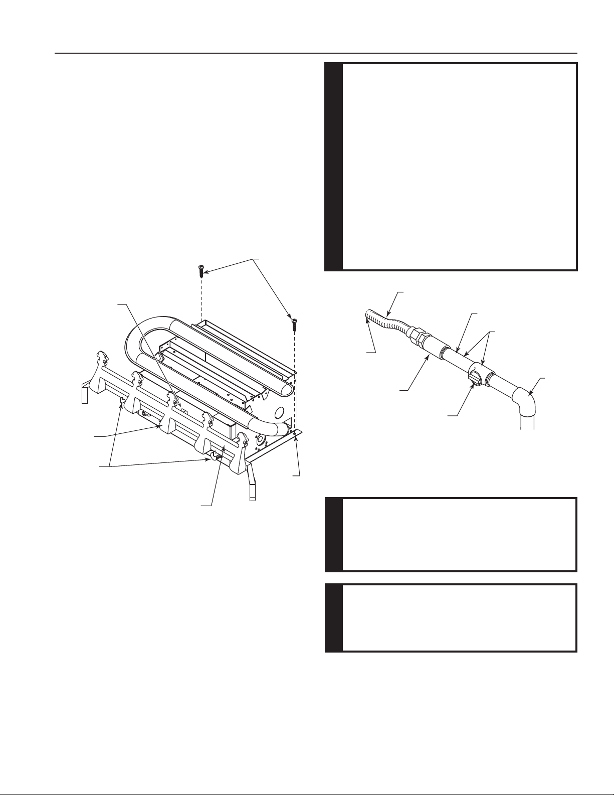
1. Center the gas log unit in the replace or rebox.
2. Install Grate: Insert longest middle grate bar in one of
the two square holes in control panel. Figure 12. Be sure
grate is centered. Sit horizontal bar inside two hooks
on front of control panel. Figure 12. Make certain front
feet of grate are located inside front edge of replace
or rebox.
3. Anchor holes are located on the ange of the unit. Figure
12. After centering the burner correctly, mark the hole
positions on the replace/rebox oor. Drill two (2) 5/32"
diameter holes approximately 11⁄2" deep.
4. Anchor the unit to the replace/rebox oor using the
screws provided. Figure 13.
Screws
Hole for
Grate Bar
Use new black iron or steel pipe. Internally
tinned copper or copper tubing can be
used per National Fuel Code, section 2.6.3,
providing gas meets hydrogen sulfide
limits, and where permitted by local codes.
Gas piping system must be sized to provide
minimum inlet pressure (Listed on Data
Plate) at the maximum ow rate (BTU/Hr).
Undue pressure loss will occur if the pipe
is too small.
CAUTION
A manual shutoff valve must be installed
upstream of the appliance. Union tee
and plugged 1/8" NPT pressure tapping
point should be installed upstream of the
appliance. Figure 13
Stainless
Flexible
Tube
To
Heater
Valve
Pipe
Possible Locations
for Pressure
Tapping Point
Middle
Grate Bar
Hooks for
Grate
Horizontal
Grate Bar
Figure 12 Install Grate and Secure Heater to Floor
of Fireplace/Firebox
Anchor
Hole
CONNECT THE GAS LINE
NOTICE: A qualied gas appliance installer must
connect the heater to the gas supply. Consult all local
codes.
Pipe
Coupling
Manual Shutoff
Valve
Figure 13 Gas Connection
Gas
Supply
Inlet
FP2371
IMPORTANT: Hold heater valve rmly with a wrench to
prevent movement when connecting to inlet pipe.
CHECK GAS TYPE: The gas supply must
be the same as stated on the heater’s rating plate. If the gas supply is different, DO
NOT INSTALL THE HEATER. Contact your
WARNING
dealer for the correct model.
Connecting directly to an unregulated propane/LPG tank can cause an explosion.
WARNING
Always use an external regulator for all propane/LPG
heaters and high pressure one to two-pound systems
only, to reduce the supply tank pressure to a maximum of
13" w.c. This is in addition to the internal regulator in the
heater valve.
Monessen • PH18/24 Installation/Owner's Manual • 65D2035 • Rev E • 01/19
13
Page 3

PH Gas Logs
INSTALLATION
CHECK GAS PRESSURE
The heater gas inlet connection is a 3/8" NPT at the valve.
All units have the inlet connection on the right side, when
you face the unit. To connect from the opposite side, route
the pipe under the rear portion of the unit.
When tightening up the joint to the valve, hold the valve
securely to prevent movement.
Test all gas joints from the gas meter to the heater valve
for leaks using a gas analyzer or soap and water solution
after completing connection. DO NOT USE AN OPEN
FLAME.
Check the gas pressure with the appliance burning and
the control set to HIGH.
MANUAL CONTROL
Figure 14
The pressure regulator is preset and locked to discourage tampering. If the pressure is not as specied,
replace the regulator with the correct part from the parts
list in this manual.
Remove 1/8" NPT plug, located on side of regulator body.
Install tting and tubing to pressure gauge. After taking
pressure reading, reinstall test plug. Check for gas leaks.
MILLIVOLT CONTROL
Figure 15
The valve regulator controls the burner pressure which
should be checked at the pressure test point.
Turn captured screw counter clockwise two or thre turns
and then place tubing to pressure gauge over test point
(Use test point “OUT” closest to control knob). After taking pressure reading, be sure and turn captured screw
clockwise rmly to re-seal. Do not over torque. Check for
gas leaks.
Test Port “Out”
FP2372
NPT Test Plug
Figure 14 Manual Control Pressure
Test Point Location
Figure 15 Millivolt Control Pressure
Test Point Location
FP2499
14
Monessen • PH18/24 Installation/Owner's Manual • 65D2035 • Rev E • 01/19
 Loading...