

Monessen Hearth VWF18N, VWF24N, VWF36, VWF30N Installation And Operating Instructions Manual
Page 1
®
This gas log set is to be installed
only in a solid-fuel burning fi replace
with a working fl ue constructed of
VWF18N VWF24N VWF30N VWF36
VENTED GAS LOG SET
WARNINGS
– Do not store or use gasoline or other fl ammable
vapors and liquids in the vicinity of this or any
– WHAT TO DO IF YOU SMELL GAS
• Do not try to light any appliance.
• Do not touch any electrical switch; do not use any
• Immediatel y call your gas suppl i e r from a
• If you cannot reach your gas supplier, call the
– Installation and service must be performed by
Page 2

........................
...
.............................................
........................
.........................................................
........
......
......
Wiring (Milli-volt)
.......................................
...............................................
.....
VWF18MO Log Placement
VWF24MO Log Placement
.........................
VWF30MO Log Placement
VWF36MO Log Placement
.........................
VWF18AO/24AO/36AO Log Placement
VWD24B Log Placement
..
VWF18SPA/24SPA Log Placement
...........
VWF30SPA Log Placement
........................
..............
........
..........................................
.................................
.........................................
Assembly
American Oak Logs
....................................
...................................
Warranty
Page 3
place with minimum venting requirements, see instal-
More frequent cleaning may be required due to exces-
be kept clean.
high surface temperature and should stay away to avoid
burns or clothing ignition.
piping system by closing its individual manual shutoff
piping system at test pressures equal to or less than 1/2
psig (3.5kPa).
MVVKLP kits.
WARNING
removed or welded in the full open position. In addition, a
Flex line installation must not exceed 36".
WARNING
WARNING
Page 4
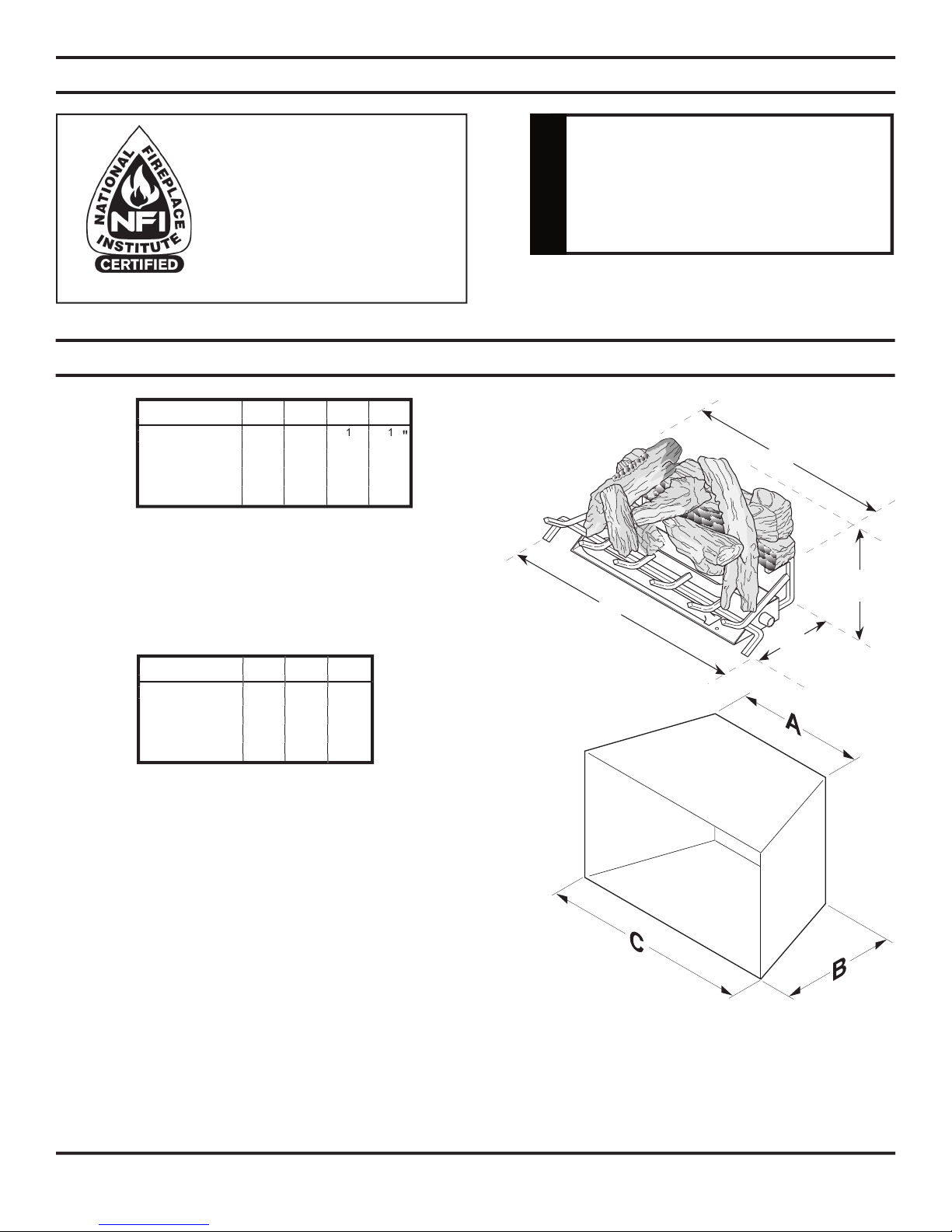
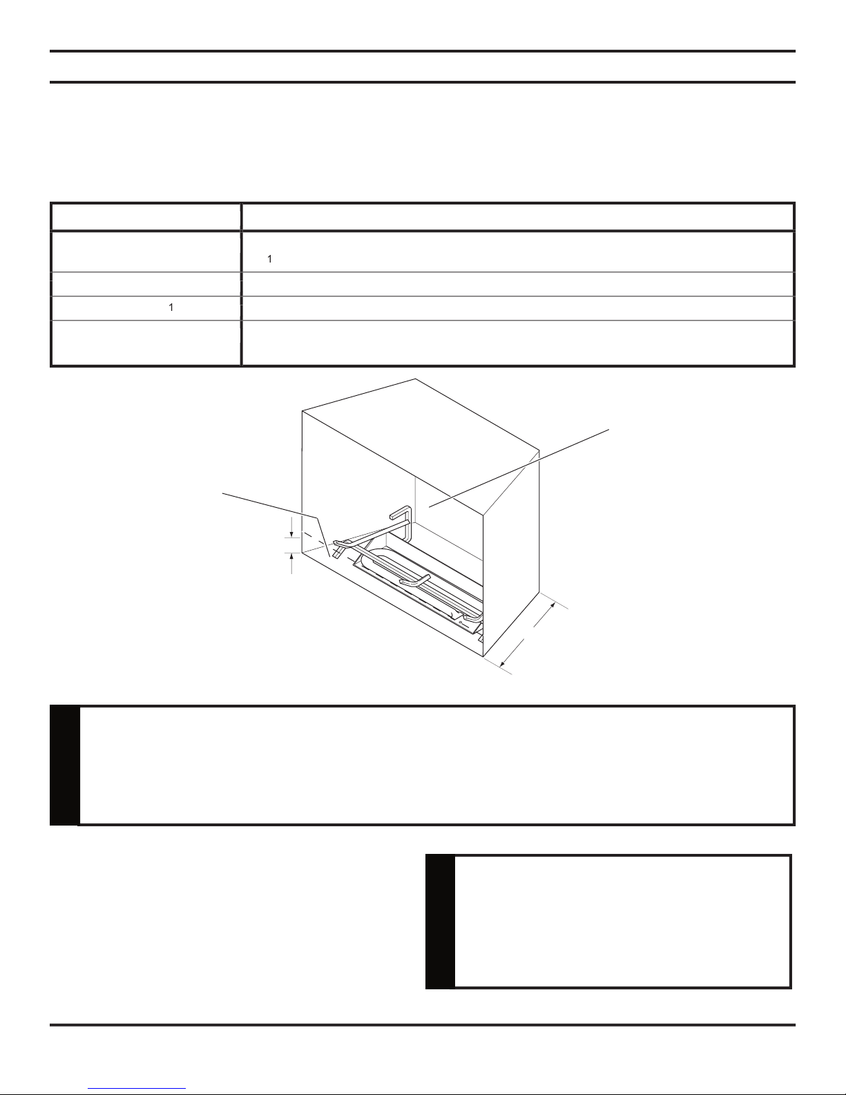
D
C
A
B
Model A B C
VWF18N
17" 13" 20"
23" 13" 26"
VWF30N
24" 13" 32"
VWF36N
36" 13" 34"
LP.
VWF18N 80,000 VWF30N 90,000
VWF24N 90,000 VWF36N 90,000
Model A B C D
VWF18N
18" 12" 12
/
/
VWF24N
24" 12" 14" 20"
VWF30N
30" 11" 18" 26"
VWF36N
36" 12" 20" 28"
www.nfi certifi ed.org
®
wellhead gas.
WARNING
Page 5
Chimney Height Flue Opening
6' 64 sq in
8' 64 sq in
10' 64 sq in
15' 51 sq in
20' 51 sq in
30' 51sq in
Chimney Height Flue Opening
• Burner and Grate Weldment Assembly • Lava Rocks (x2) • Reducer
• Glowing Embers (Rock Wool) • Damper Clamp • Injector
• Installation /Operating Instructions • Vermiculite •
/
/
• Shield Plate 90° Elbow,
/
/
• Individual Logs • Installation Instructions
Ensure that the following items are available before proceeding with installation:
• External regulator (for propane/L.P.G. only) • Shutoff valve • Pipe wrench
• Piping which complies with local codes • Drill with masonry bit (for mounting to the fl oor)
• Pipe sealant approved for use with propane/L.P.G. (Resistant to sulfur compounds)
WARNING
WARNING
Page 6
with adjustable
fully open
while the unit is in
will potentially void the warranty.
WARNING
Height of Restriction (X) Minimum Depth of Fireplace/Firebox
/
0 to 1.5" 15"
Greater than 1
/
Greater than 3: Any barrier greater than three inches (3") placed in front of the gas log set is not
CAUTION
Page 7
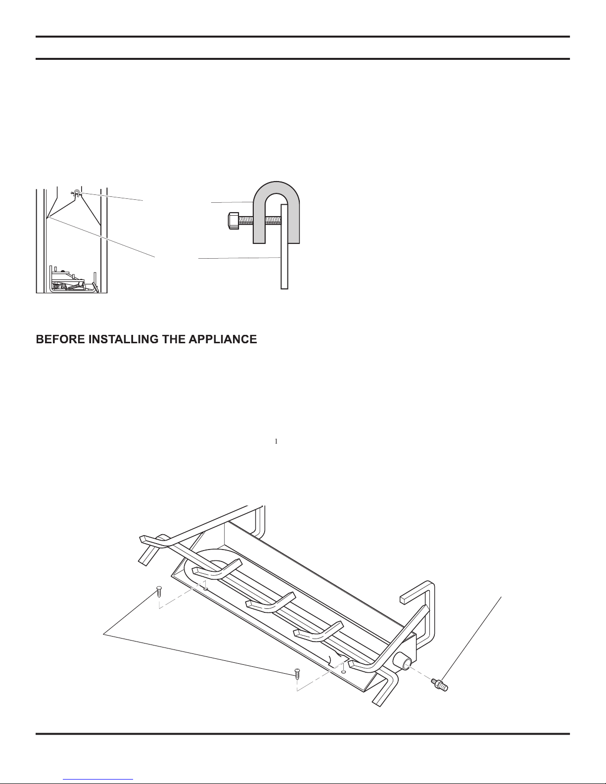
Damper Stop
Damper
• Turn off gas supply to fi replace or fi rebox.
• Clean fi replace fl oor and chimney before installing log set. Seal any ash. Clean out doors to protect the unit
ASSEMBLY PROCEDURE
2. Drill two (2)
/
/
3. Anchor the front pan to the fl oor using the screws provided.
4 of the fi replace damper blade and provide a minimum fl ue opening, per table on page 5.
removed or welded in the full open position. In addi-
Massachusetts.
Page 8
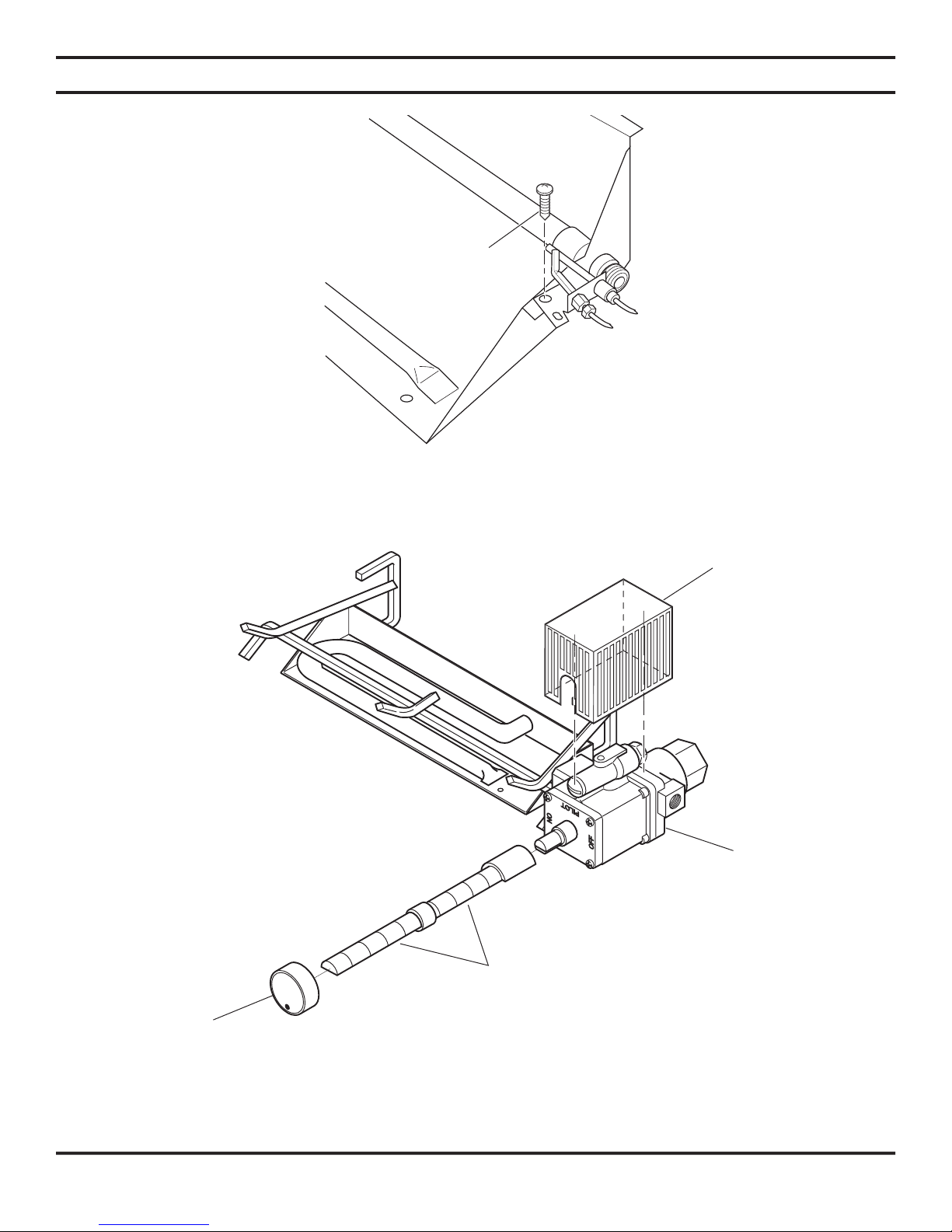
Adjust pilot fl ame to
WARNING
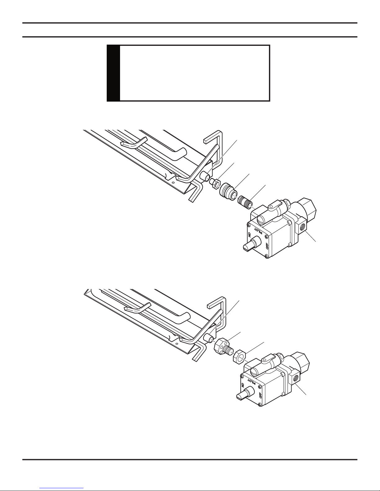
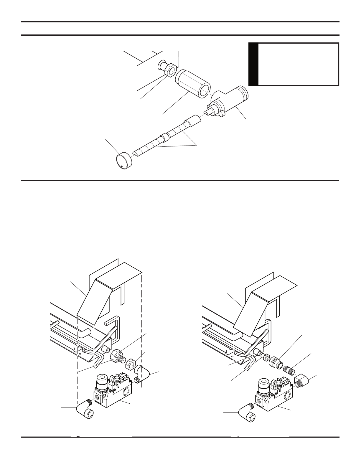
Natural Gas Injector
Valve
Valve
Valve
Valve
Air Mixing Nut
Page 9
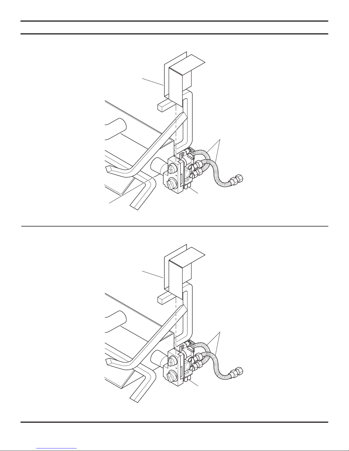
Valve
Page 10
Valve
WARNING
Valve
Air Mixing Injector
Vermiculite
Valve
Valve
Valve
Page 11
Valve
Valve
Air Mixing Nut
Vermiculite
Air Mixing Nut
Valve
Valve
Page 12

Valve
WIRING (MILLI-VOLT)
be checked with a milli-volt meter having a 0-1000MV
range. Conduct each check shown in chart below by
A. COMPLETE MILLI-VOLT SYSTEM CHECK
a. If the reading is more than 100 milli-volts and the automatic valve still does not come on — replace the control.
b. If the closed circuit reading (“A” reading) is less than 100 milli-volts, determine cause for low reading —
proceed as follows:
a. 325 milli-volts minimum. If the minimum milli-volt reading is not obtainable, readjust pilot for maximum milli-volt
CONNECT
CHECK TO LEADS TO READING
TEST TEST TERMINALS SHOULD BE
A COMPLETE TH & THTP CLOSED
SYSTEM
B THERMOPILE TH & THTP OPEN
OUTPUT
WARNING
Do not connect to 110
volt supply.
WARNING
WARNING
Page 13

Valve
Valve
Always use an external regulator for all propane/LPG gas logs only,
to reduce the supply tank pressure to a
A manual shutoff valve must be installed upstream of the appliance. Union tee and
CAUTION
WARNING
Page 14

#1
#2
#3
#4
#5
#6
2"
Fill the burner pan with vermiculite to the bottom of the rear log and sloped to the front edge of the burner pan. Excess ver-
/
burner evenly. Do no use more rock wool than the amount supplied with the unit. To enhance the appearance of the Wildfi re
VWF18MO LOG PLACEMENT
1. Slide shield plate down back of burner pan.
Figure 17
2. Center rear log #1 on grate bars and fl ush with rear of
3. Place front left log #2 on the front of the plate and to the
4. Place front right log #3 on the front of the plate and to
5. Install left crossover log #4 as shown.
6. Install right crossover log #5 as shown.
7. Install top log #6 as shown.
Page 15

#1
#2
#3
#4
#5
#6
#7
2"
#1
#2
#3
#4
#5
#7
#6
#8
2"
VWF24MO LOG PLACEMENT
1. Slide shield plate down back of burner pan.
Figure 18
2. Center rear log #1 on grate bars and fl ush with rear of
3. Place front left log #2 on the front of the plate and to the
4. Place front right log #3 on the front of the plate and to
NOTE: Allow 2" between the back log and the
5. Install left log #4 as shown.
6. Install right top log #5 as shown.
7. Install left top log #6 as shown.
8. Install top crossover log #7 as shown.
VWF30MO LOG PLACEMENT
1. Slide shield plate down back of burner pan.
Figure 19
2. Center rear log #1 on grate bars and fl ush with rear of
3. Place front left log #2 on the front of the plate and to the
4. Place front right log #3 on the front of the plate and to
5. Install left middle log #4 as shown.
6. Install right middle log #5 as shown.
7. Install right top log #6 as shown.
8. Install left top log #7 as shown.
9. Install top crossover log #8 as shown.
Page 16

2"
#8
#6
#7
#9
#10
#11
#5
#4
#2
#1
#3
Figure20
4. Place center front log #3 on middle grate prong.
Figure 20.
NOTE: Allow 2" between the back log and the
Page 17

Accessory
#1
#3
#4
#5
#6
#7
#2
#8
1. Place Back Log #1 on grate bars on back of grate.
Figure 22
2. Place Front Log #2 on front of grate.
3. Position Right Log #3 on top right of Log #1 and Log
#2. Make sure back of Log #3 fi ts in right grove in top
4. Place Left Log #4 on top left of Log #1 and Log #2.
Make sure back of Log #4 fi ts in left grove in top of Log
#1.
5. Rest Top Right Log #5 on Log # 3 and Log #2.
Figure 22
6. Rest Top Left Log #6 on Log #4 and Log #2.
7. Place Log #7 on Log #2 and Log #5.
8. Place Log #8 on Log #3 and Log #7.
Page 18

1. Slide shield plate down back of burner pan.
Figure 22
2. Place Back Log #1 on grate bars on back of grate.
Figure 24.
3. Place Middle Log #2 in front of Log #1 .
Figure 22.
4. Position Right Front Log #3 on right front side of grate.
5. Position Left Front Log #4 on left front side of grate.
Make sure notch in bottom of log sits on grate prong.
6. Rest Top Right Log #5 across top right sides of Log #1
7. Rest Top Left Log #6 across top left side of Log #1 and
Log #2.
#2
#5
#1
Page 19

26
4. Place end of Bottom Right Log #3 on cutout of back
Rest Front Right Log #8 on top
right log #4 and front of burner pan.
#1
#2
#3
#5
#6
#8
#4
AND VWF36/30SRO
(8 LOGS)
#7
#8
Page 20

Log #1B on front right of the grate.
4. Fit cutout in the bottom left of Rear Log #3 over the back end of log
#2. Rest right end of Log #3 on rear grate bar.
#1. Rest back end of Log #5 on Log #4.
#6.
#8
#2
#4
#1A
#5
#7
#6#3#6
#1B
Page 21

Accessory Cover
Log #1B on front right of the grate.
4. Fit cutout in the bottom left of Rear Log #3 over the back end of
back end of Log #5 on top right of Log #3.
#1.
#8 rest on Log #6.
#1A
#2
#3
#4
#5
#7
#6
#8
#9
#1B
Page 22

to “OFF.”
to “PILOT.” Push in control knob for 5 seconds.
hold the control knob in for about one (1) minute after the pilot is lit. Release knob and it
• If knob does not pop up when released, stop and immediately call your service technician
• If the pilot will not stay lit after several tries, turn the gas control knob to off and call
to “ON.”
FOR YOUR SAFETY READ BEFORE LIGHTING
MANUAL CONTROL LIGHTING INSTRUCTIONS
WHAT TO DO IF YOU SMELL GAS:
• Do not attempt to light any appliance.
• Do not touch any electric switch; do not use any phone in your building.
• Immediately call your gas supplier from a neighbor's phone. Follow the gas supplier's instructions.
• If you cannot reach your gas supplier, call the fi re department.
result in a fi re or explosion.
Do not use this appliance if any part of it has been under water. Immediately call a qualifi ed service tech-
been under water.
because some gas is heavier than air and will settle
to
position. Do not force.
WARNING
Page 23

O
N
OFF
P
I
I
L
O
T
1. Turn control knob clockwise
to OFF position to completely shut off the heater.
2. If applicable: Turn ON/OFF switch to OFF position.
MILLI-VOLT CONTROL LIGHTING INSTRUCTIONS
to the “OFF” position, and turn ON/OFF switch to “OFF” position.
position, turn the gas control knob counterclockwise
to “PILOT” position. Push
to the “ON” position.
position.
and call your service
Page 24

WARNING
because some gas is heavier than air and will settle on the fl oor.
WHAT TO DO IF YOU SMELL GAS:
• Do not attempt to light any appliance.
• Do not touch any electric switch; do not use any phone in your building.
• Immediately call your gas supplier from a neighbor's phone. Follow the gas supplier's instructions.
• If you cannot reach your gas supplier, call the fi re department.
result in a fi re or explosion.
Do not use this appliance if any part of it has been under water. Immediately call a qualifi ed service tech-
been under water.
1. STOP! Read the safety information label.
2. WARNING: BE SURE THE CHIMNEY DAMPER IF FULLY OPEN.
3. Make sure the manual shutoff valve is fully open, and the gas contol valve is fully off.
4. Wait fi ve (5) minutes to clear out any gas. Then smell for gas, including near the fl oor. If you smell gas,
5. Place a burning match on the surface of the burner embers (granules). Do not hold the match in hand.
to “ON”.
6. If the burner does not light before the match goes out, immeadiately turn the manual valve clockwise
to “OFF”
1. Turn the manual valve clockwise
to “OFF.”
MANUAL CONTROL LIGHTING INSTRUCTIONS
FOR YOUR SAFETY READ BEFORE LIGHTING
WARNING
Page 25

Flame should be yellow and extend vertically (not curling toward fi replace screen).
use this appliance with glassed doors closed. This could cause the pilot to go out and severe sooting outside the fi replace.
Page 26

place a match or smoke stick along the top and sides of the fi replace opening. If the fl ame or smoke is not pulled into the
within the room.This effect can be a sign of a blocked chimney, a faulty vent system or
WARNING
Page 27

be placed outside of the fi replace.
WARNING
Page 28

Item Description VWF(18,24,30)NM NG LP MVVKN MVVKLP MXVKN MXVKLP
2 Manual Control Valve 27D0303 27D0304 27D0304 — —
3 Milli-volt Control Valve — — — 27D0800 32D0211 — —
4 Hi/Lo Remote Control Valve — — — — — 27D8521 27D8522
5 Pilot — 27D0301 27D0302 27D7027 27D7028 27D7027 27D7028
6 Shaft Extender (Manual) 27D0410 27D0410 27D0410 — — — —
(2 required)
7 Control Knob 27D0417 27D0602 27D0602 — — — —
ASSEMBLY
Page 29

#1
#2
#3
#4
#5
#7
#6
#8
#8
#6
#7
#9
#10
#11
#5
#4
#2
#1
#3
2 Left Front Log 27D7501 27D7507 27D7511
3 Right Front Log 27D7502 27D7508 27D7512
4 Left Side Middle Log 27D7503 27D7503 27D7503
5 Right Side Middle Log 27D7504 27D7504 27D7504
6 Right Top Log 27D7505 27D7505 27D7505
7 Left Top Log — 27D7509 S7D7509
8 Top Crossover Log — — 27D7513
2 Left Front Log 27D7501 27D7507 27D7511
3 Right Front Log 27D7502 27D7508 27D7512
4 Left Side Middle Log 27D7503 27D7503 27D7503
5 Right Side Middle Log 27D7504 27D7504 27D7504
6 Right Top Log 27D7505 27D7505 27D7505
7 Left Top Log — 27D7509 S7D7509
8 Top Crossover Log — — 27D7513
Item Description Qty 36MO
1 Rear Log 1
2 Left Front Log 1
3 Center Front Log 1
4 Right Front Log 1
5 Left Side Log 1
6 Right Side Log 1
7 Right Side Middle Log 1
8 Top Log 1 27D8586
9 Top Log 1
11 Top Left Log 1
Page 30

#1
#3
#4
#5
#6
#7
#2
#8
Item Description Qty VWF24B
1 Back Log 1 27D1026
2 Middle Log 1 27D1025
3 Right Front Log 1 27D1024
4 Left Front Log 1 27D1023
5 Top Right Log 1 27D1028
6 Top Left Log 1 27D1027
Item Description Qty VWF24B
#1
#2
#3
#4
#5
#6
Item Description VWF18AO VWF24AO VWF30AO
2 Back Log 27D8577 27D8585 27D8593
3 Right Middle Log 27D8580 27D8588 27D8596
4 Left Middle Log 27D8581 27D8589 27D8597
5 Top Right Log 27D8578 27D8586 27D8594
6 Top Left Log 27D8579 27D8587 27D8595
7 Top Center Log — — 27D8598
8 Top Top Center — — 27D8599
AMERICAN OAK LOGS
Page 31

#1
#2
#3
4#
#5
6#
7#
8#
Item Description Qty VWF24SRO VWF30SRO VWF36SRO
1 Back Log 1 27D8800 27D8807 27D8814
2 Bottom Left Log 1 27D8801 27D8808 27D8815
3 Bottom Right Log 1 27D8802 27D8809 27D8816
4 Top Right Log 1 27D8803 27D8810 27D8817
5 Bottom Front Left Log 1 27D8804 27D8811 27D8818
6 Top Left Log 1 27D8805 27D8812 27D8819
7 Center Top Log 1 27D8806 27D8813 27D8820
8 Front Right Log 1 — — 27D8821
Page 32

#1A
#1B
#1A
#1B
#2
#2
#3
#3
#4
#4
#5
#5
#6
#6
#7
#7
#8
#8
#9
Item Description Qty VWF18SP VWF24SP VWF30SP
1A Front Left Log 1 27D8700 27D8702 27D8704
1B Right Front Log 1 27D8701 27D8703 27D8705
2 Side Support Log 1 27D8551 27D8559 27D8567
3 Rear Log 1 27D8552 27D8560 27D8568
4 Right Log 1 27D8553 27D8561 27D8569
5 Right Middle Log 1 27D8554 27D8562 27D8570
6 Left Log 1 27D8555 27D8563 27D8571
7 Top Center Log 1 27D8556 27D8564 27D8572
8 Top Left Log 1 27D8557 27D8565 27D8573
9 Top Top Left Log 1 — — 27D8574
Page 33

Page 34

Page 35

Page 36

Monessen Hearth Systems (MHS) warrants the components and materials in your gas appliance to be free from
MHS will, at its option, replace or repair the defective components at no charge to the original owner. MHS
by a dated proof of purchase.
by an authorized service representative.
MHS reserves the right to investigate any and all claims against the Limited Warranty and decide upon
Monessen Hearth Systems
149 Cleveland Drive
Paris, Kentucky 40361
 Loading...