

Page 1
Installation & Operating Manual
!
Installation and Appliance Setup - Care and Operation
INSTALLER: Leave this manual with party responsible for use and operation.
OWNER: Retain this manual for future reference.
Call your dealer for questions on Installation, Operation, or Service.
NOTICE: SAVE THESE INSTRUCTIONS
Sundance® Vent Free Gas Heater
Models: SD30PV, SD30NV
INSTALLER: Leave this manual with the appliance.
CONSUMER: Retain this manual for future reference.
WARNING
If the information in this manual is not followed exactly,
a re or explosion may result causing property damage,
personal injury or loss of life.
—Do not store or use gasoline or other ammable vapors
and liquids in the vicinity of this or any other appliance.
—WHAT TO DO IF YOU SMELL GAS
• Do not try to light any appliance.
• Do not touch any electrical switch; do not use any
phone in your building.
• Immediately call your gas supplier from a neighbor’s
phone. Follow the gas supplier’s instructions.
• If you cannot reach your gas supplier, call the re
department.
Installation and service must be performed by a qualied
installer, service agency or the gas supplier.
This appliance may be installed in an aftermarket*
permanently located manufactured (mobile) home where
not prohibited by local codes.
This appliance is only for use with the type of gas indicated
on the rating plate.
This appliance is not convertible for use with other gases
unless a certied kit is used.
*Aftermarket: Completion of sale, not for purpose of resale,
from the manufacturer.
This is an unvented gas-red heater. It uses air (Oxygen)
from the room in which it is installed. Provisions for adequate
combustion and ventilation air must be provided. Refer to
the Fresh Air Requirements section for further information.
1
3-90-733069Monessen • Sundance VF Installation Manual_R1 • 04/17
Page 2

PLEASE READ THE INSTALLATION & OPERATING INSTRUCTIONS BEFORE USING APPLIANCE.
Thank you and congratulations on your purchase of a Monessen stove.
IMPORTANT: Read all instructions and warnings carefully before starting installation. Failure to follow these instructions may
result in a possible re hazard and will void the warranty.
Table of Contents
1 Safety & Operations
A. Important Safety Information .................................... 3
B. Stove Dimensions .................................................... 4
C. Clearance to Combustibles ...................................... 5
D. Floor Protection........................................................ 5
E. Gas Specications ................................................... 6
F. Gas Inlet & Manifold Pressures ................................ 6
G. High Elevations ........................................................ 6
H. Odor During Operation............................................. 6
I. Vent Free Features .................................................... 7
J. Fresh Air Requirements ............................................ 7
2 Assembly
A. Unpack the Stove ..................................................... 8
B. Install Optional Fan .................................................. 8
C. Install On/Off Switch ................................................ 9
D. Thermostat Connection ............................................ 9
E. Connect the Gas Supply Line ................................ 10
F. Install Log Set ......................................................... 10
3 Operation
A. Your First Fire ......................................................... 12
B. Pilot & Burner Inspection........................................ 12
C. Flame & Temperature Adjustment .......................... 12
D. Flame Characteristics ............................................ 12
E. Lighting Instructions ............................................... 13
4 Troubleshooting Guide ......................................... 14
5 Maintenance
A. Cleaning Firebox & Inspection ............................... 16
B. Cleaning Procedure ............................................... 16
C. Glass Replacement................................................ 16
D. Care of Cast Iron.................................................... 16
6 Reference Materials
A. Service Parts List ................................................... 18
B. Fan Kit .................................................................... 18
C. Remote Controls .................................................... 18
D. Warming Shelf ....................................................... 18
E. Warranty ................................................................. 19
= Contains updated information
Proposition 65 Warning: Fuels used in gas, woodburning
or oil red appliances, and the products of combustion
of such fuels, contain chemicals known to the State
of California to cause cancer, birth defects and other
reproductive harm.
California Health & Safety Code Sec. 25249.6
2
3-90-733069Monessen • Sundance VF Installation Manual_R1 • 04/17
Page 3
1
Safety & Operations
A. Important Safety Information
In order to ensure safe and effective installation, this unit
must be installed only by a qualied agency, individual, rm,
corporation or company that is experienced in the installation,
repair and servicing of this type of appliance and is familiar
with the building codes and installation techniques appropriate
in your area. Contact your hearth products dealer or local gas
supplier for the name of a qualied service person.
In the Commonwealth of Massachusetts, all gas ttings and
installation of this heater shall only be done by a licensed
gas tter or licensed plumber.
IMPORTANT: Read this owner’s manual carefully and
completely before trying to assemble, operate, or service
this heater. Improper use of this heater can cause serious
injury or death from burns, re, explosion, electrical shock,
and carbon monoxide poisoning. Failure to follow instructions
may result in property damage, bodily injury or loss of life.
This manual contains important user information. Keep this
manual with the heater after installation is complete.
FOR SAFE INSTALLATION AND OPERATION, PLEASE
NOTE THE FOLLOWING:
1. Use only Natural Gas with model 4050. Use only Propane
with model 4051. Do not use any other fuels.
2. Install only in accordance with the National Fuel Gas
Code, ANSIZ223.1/NFPA54-latest edition. (Exception: Do
not derate this appliance for altitude. This appliance has
been tested and listed for use in altitudes up to 10,000
feet.)
3. Use only the installation instructions provided by the
manufacturer for this appliance. Installation and repair
should be done by a qualied installer, preferably NFI
or WETT (Canada) certified. The appliance should
be inspected before use and at least annually by a
professional service person. More frequent cleaning may
be required due to excessive lint from carpeting, bedding
material, etc. It is imperative that control compartments,
burners and circulating air passageways of the appliance
be kept clean.
4. WARNING: Any change to this heater or its controls can
be dangerous. DO NOT make modications to any heater
or associated parts.
5. DO NOT install this heater in a bedroom or bathroom.
6. Due to high surface temperatures, DO NOT install this
heater
• in a recreational vehicle,
• where curtains, furniture, clothing or other ammable
objects are less than 36 inches from the front, top or
sides of the heater,
• in high trafc areas,
• in windy or drafty areas.
7. DO NOT place clothing or other ammable material on or
near the appliance.
CARBON MONOXIDE POISONING
MAY LEAD TO DEATH!
Carbon Monoxide Poisoning: Early signs of carbon
monoxide poisoning resemble the u, with headaches,
dizziness, or nausea. If you have these signs, the heater
may not be working properly. Get fresh air at once! Have
the heater serviced. Some people are more affected by
carbon monoxide than others. These include pregnant
women, people with heart or lung disease or anemia, those
under the inuence of alcohol, and those at high altitudes.
8. DO NOT obstruct the top grille at all. Doing so will cause
high levels of carbon monoxide that will lead to death.
9. This heater needs fresh, outside air ventilation to operate
properly. Refer to Fresh Air Requirements.
10. This heater shall not be installed in a room or space
unless the required volume of indoor combustion air is
provided by the method described in the National Fuel
Gas Code, ANSI Z223.1/NFPA 54, the International Fuel
Gas Code or applicable local codes.
11. If heater shuts off, heater may not have enough fresh
air ventilation. Provide more fresh air. If heater keeps
shutting off, refer to Troubleshooting.
12. DO NOT operate this heater
• where ammable liquids or vapors are used or stored
• under dusty conditions.
13. The heater becomes very hot when operating. Alert
children and adults to stay away from hot surfaces to
avoid burns or clothing ignition. The heater will remain
hot for a time after shutdown. Allow surface to cool before
touching.
14. Carefully supervise young children when they are in the
room with the heater.
15. Do not use the heater if any part has been exposed
to or under water. Immediately call a qualied service
technician to inspect the room heater and to replace any
part of the control system and any gas control which has
been under water.
16. DO NOT operate the heater if any log is broken or
damaged.
17. Turn heater off and let cool before servicing. Only a
qualied service person should service and repair heater.
18. DO NOT operate this appliance with the safety screen
removed. If the safety screen is removed from the
appliance for service or cleaning, it must be replaced
before operating the heater.
NOTE: If any of the original wire as supplied with the
appliance must be replaced, it must be replaced with a wire
of at least 105°F temperature rating.
3
3-90-733069Monessen • Sundance VF Installation Manual_R1 • 04/17
Page 4
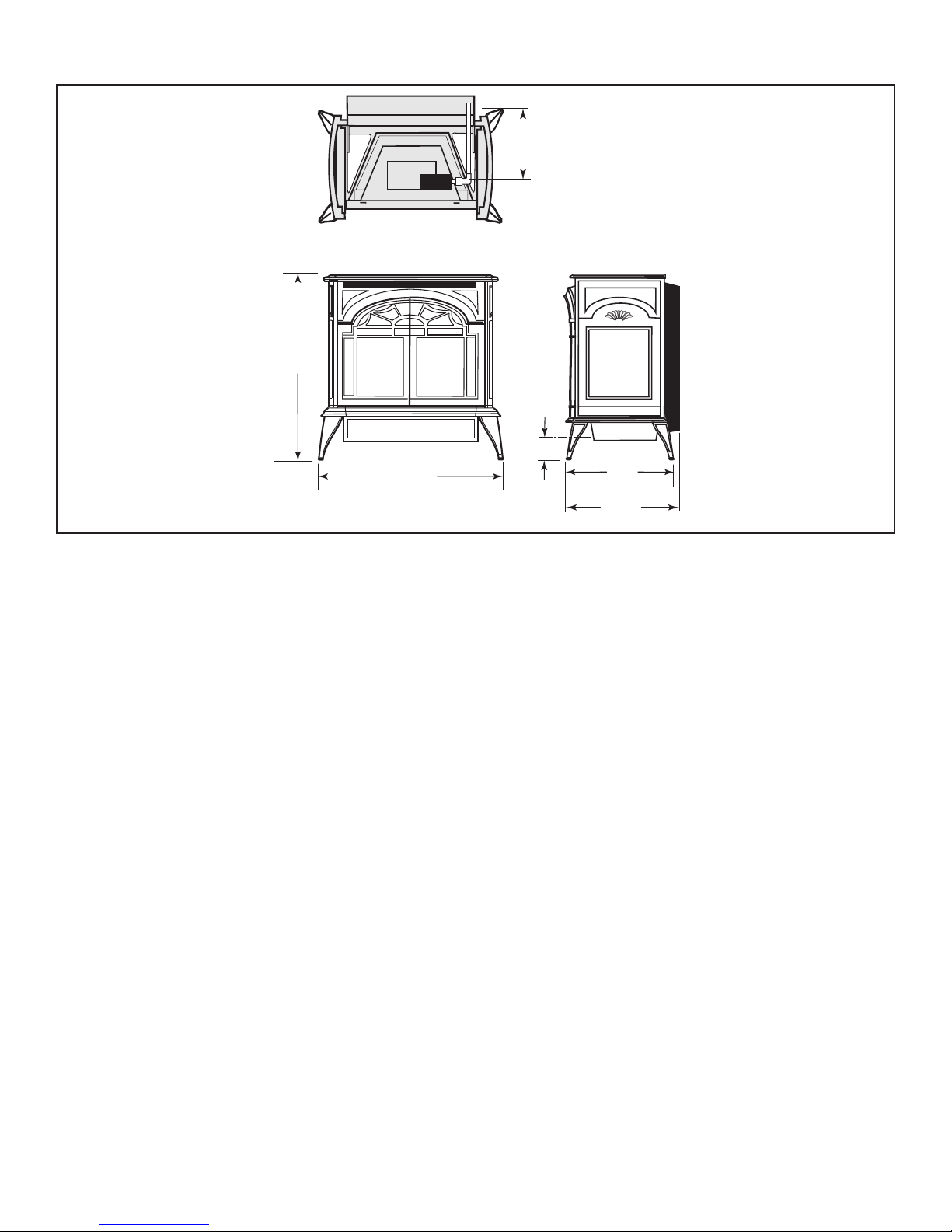
B. Stove Dimensions
C
L
C
L
9"
(229 mm)
26³⁄₄"
(680 mm)
3"
(76 mm)
Valve Inlet
14¹⁄₂"
(368 mm)
Valve Inlet
15⁵⁄₈"
(379 mm)
25¹⁄₂"
(648 mm)
Freestanding Stove
Drawing Not to Scale
Figure 1 - Sundance freestanding shell dimensions.
4
3-90-733069Monessen • Sundance VF Installation Manual_R1 • 04/17
Page 5
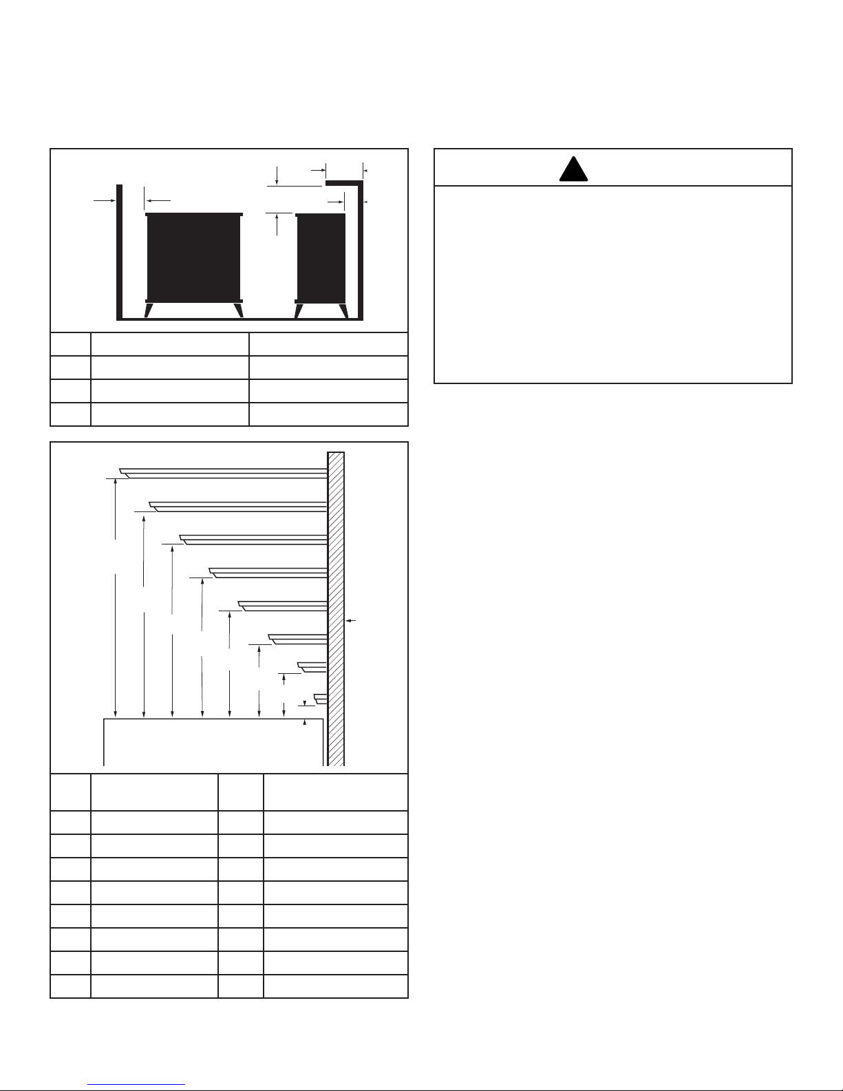
C. Clearance to Combustibles
S
T
U
V
W
X
Y
Z
A
B
C
D
E
F
G
H
B
A
C
D
!
Minimum Clearances to Combustible Materials
Maintain clearance, (empty space), between combustible
materials and the heater as specied below for the appropriate
rebox shell being installed.
A Ceiling 35” (889mm)
B Side Wall 2” (51mm)
C Rear Wall 0” (0mm)
D Max. Alcove Depth 13” (330mm)
D. Floor Protection
The Sundance must be installed on rigid ooring. If the
appliance is installed on any combustible surface other than
wood ooring, such as carpet or tile, a metal or wood panel
must be installed to extend the full length and width of the unit.
WARNING
• Do not install this heater in a bathroom or bedroom.
• Installation of this heater must conform with local codes
or, in the absence of local codes, with the National Fuel
Gas Code, ANSI Z223.1 / NFPA54.
• This heater creates warm air currents. These currents
move heat to wall surfaces next to the heater. Installing
the heater next to vinyl or cloth wall coverings or
operating the heater where impurities in the air such
as tobacco smoke exist, may discolor walls.
• Do not use a blower insert, heat exchanger insert or
other accessory not approved for use with this heater.
Mantel
Ref
A 13” (330mm) S 35” (889mm)
B 11-1/4” (286mm) T 30” (762mm)
C 9-3/8” (241mm) U 25” (635mm)
D 7-1/2” (191mm) V 20” (508mm)
E 5-3/4” (146mm) W 15” (381mm)
F 4” (102mm) X 10” (254mm)
G 2-1/4” (57mm) Y 5” (127mm)
H 1” (25mm) Z 2” (51mm)
5
Shelf Depth Ref.
Mantel from
Stove Top
3-90-733069Monessen • Sundance VF Installation Manual_R1 • 04/17
Page 6
!
!
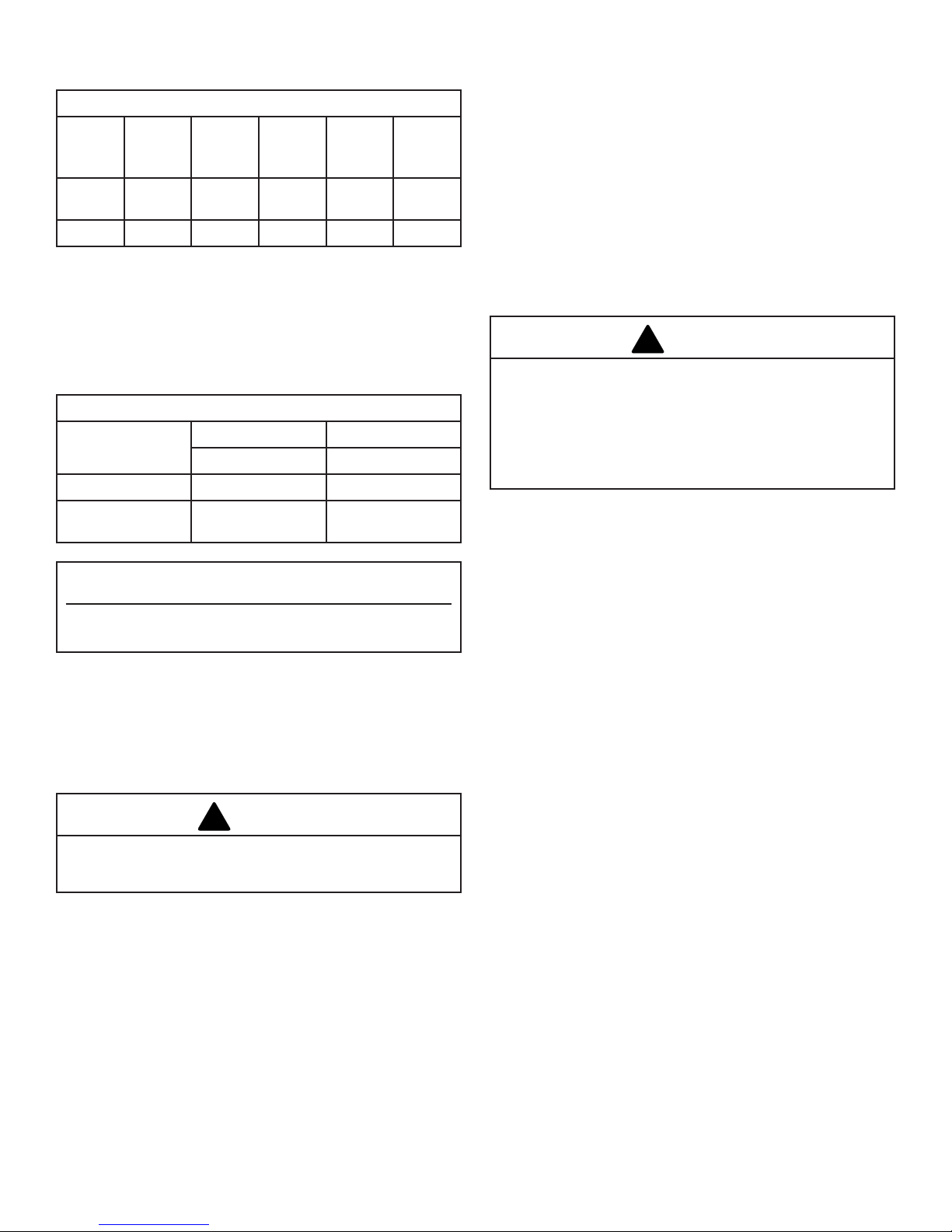
E. Gas Specications
Gas Specications
Max
Gas
Model Fuel
4050 Nat. Millivolt 28,000 19,500
4051 Prop Millivolt 28,000 19,500 N/A
*Natural Gas units with air shutter fully closed and rotated
with bend outside of burner for less restriction. Propane
units have no air shutter.
Firebox weight / shipping 110 lbs.
Control
Input
BTU/h
Min
Input
BTU/h
Air
Shutter
Setting*
Fully
Closed
G. High Elevations
Input ratings are shown in Btu per hour and are certied
without deration from elevations up to 4,500 feet (1,370
m) above sea level.
Nuisance outages may occur at altitudes above 4,500 feet
(1,370 m) if dirt, dust, lint and/or cobwebs are allowed
to accumulate on burner and/or ODS pilot. Monthly
inspection and cleaning is recommended for altitudes
above 4,500 feet (1,370 m)
For elevations above 4,500 feet (1,370 m), installations
must be in accordance with the current ANSI Z223.1/
NFPA 54 and/or local codes having jurisdiction.
WARNING
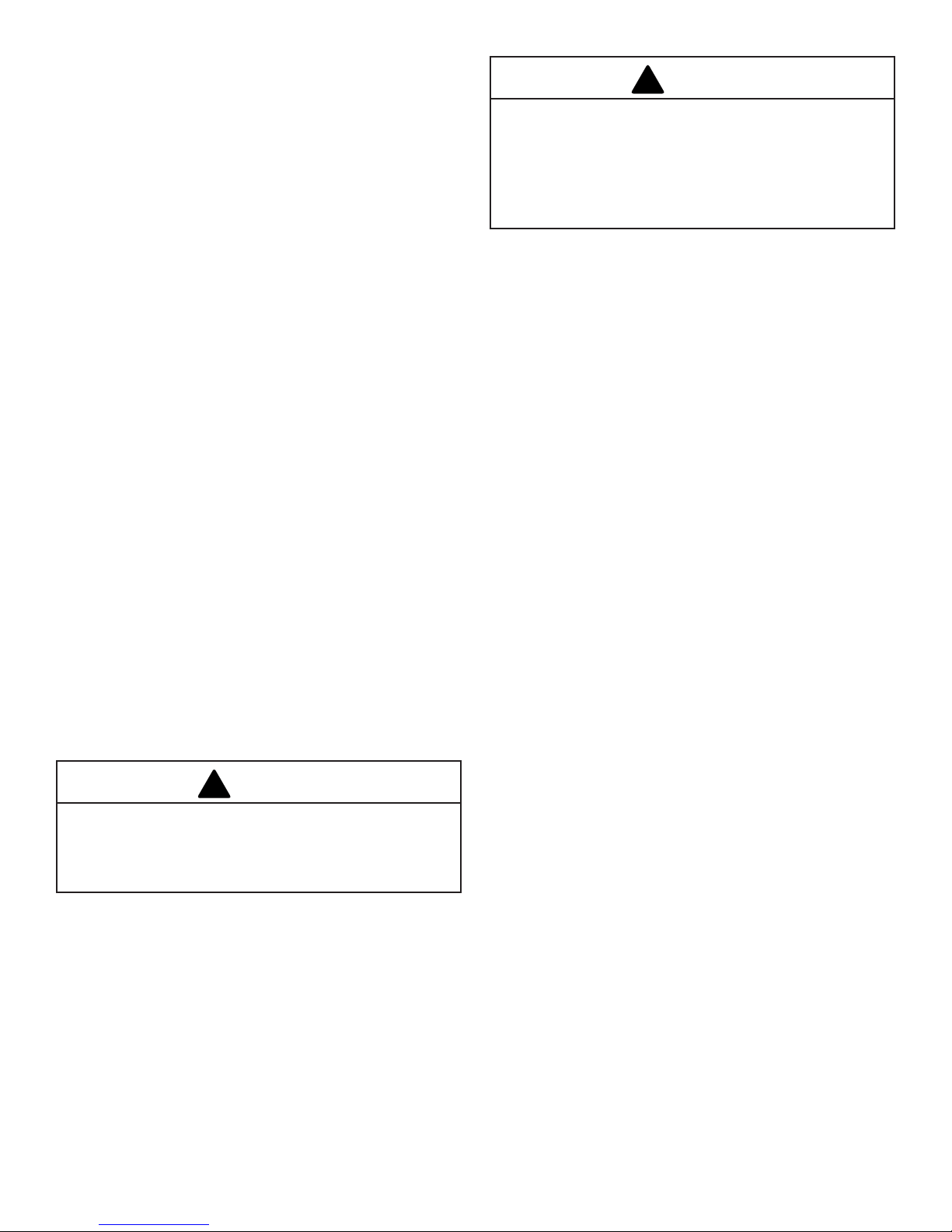
F. Gas Inlet & Manifold Pressures
Gas Inlet & Manifold Pressures
Natural LP (Propane)
Inlet Minimum
Inlet Maximum 14” w.c. 14” w.c.
Manifold
Pressure
ANSI Z21.11.2, Latest Edition
The installation of your Monessen stove must conform
with local codes, or in the absence of local codes, with the
National Fuel Gas Code ANSI Z223.1/NFPA 54 - latest edition.
(EXCEPTION: Do not derate this appliance for altitude up to
4,500 feet (1,370m). Maintain the manifold pressure at 3.5”
w.c. for Natural Gas and 11.0” w.c. for LP Gas.
5.5” w.c. 11” w.c.
3.5” w.c.
Sundance Vent-Free
Certied to:
Unvented Heaters
10” w.c. (MP)
11” w.c. (RP)
WARNING
Improper installation, adjustment, alteration, service or
maintenance can cause injury or property damage. Refer
to this manual for correct installation and operational
procedures. For assistance or additional information
consult a qualied installer, service agency, or the gas
supplier.
H. Odor During Operation
Neither natural gas nor propane gas give off an odor when
burned. The nature of a vent free combustion system,
however, is such that odors may occasionally be produced
during heater operation when impurities exist in the immediate
area. Cleaning solutions, paint, solvents, cigarette smoke,
candles, adhesives, new carpet or textiles, etc., all can create
fumes. These fumes may mix with combustion air and can
create odor. Such odors will disappear over time, however the
condition can be alleviated by opening a window or otherwise
providing additional ventilation to the area.
Failure to keep the primary air opening(s) of the burner(s)
clean may result in sooting and property damage.
6
3-90-733069Monessen • Sundance VF Installation Manual_R1 • 04/17
Page 7
I. Vent Free Features
!
!
The Sundance Vent Free gas stove is an unvented gas heating
appliance tested and listed to the ANSI standard Z21.11.2,
Latest Edition. This appliance is specically congured to
burn either Natural Gas or Propane fuel, as indicated on the
metal rating plate attached to the rear shroud. The Sundance
is not fuel convertible.
The stove is shipped fully assembled and ready for installation.
The stove is equipped with an SIT control valve that allows
thermostatic control, on/off switch or a remote switch (not
supplied).
Both models incorporate variable regulators that allow you to
adjust burner heat output between HIGH, (28,000 Btu), and
LOW, (19,500 Btu). See the Operation Section for details.
The standing pilot incorporates an Oxygen Depletion System
(ODS/pilot) designed to shut off the appliance if enough fresh
air is not available.
J. Fresh Air Requirements
Fresh Air Requirements for Combustion and Ventilation:
Modern construction standards have resulted in homes that
are highly energy-efcient and that allow little heat loss.
Your home needs to breathe, however, and all fuel-burning
appliances within it require fresh air in order to function properly
and safely. Exhaust fans, clothes dryers, replaces, and other
fuel burning appliances all use the air inside the building. If
the available fresh air is insufcient to meet the demands of
these appliances, problems can result.
The Sundance Vent Free Stove has specific fresh air
requirements. You must determine that these fresh air
requirements will be met within the space where the
appliance will be installed. The following information will
help you insure that adequate fresh air is available for the
heater to function properly.
WARNING
If the area in which the heater may be operated does
not meet the required volume for indoor combustion air,
combustion and ventilation air shall be provided by one
of the methods described in the National Fuel Gas Code,
ANSI Z223.1/NFPA 54, the International Fuel Gas Code
or applicable local codes.
WARNING
This heater must have fresh air for proper operation. If
not, poor fuel combustion could result. Read the following
instructions to insure proper fresh air for this and other
fuel-burning appliances in your home.
7
3-90-733069Monessen • Sundance VF Installation Manual_R1 • 04/17
Page 8

MOT OR
SNAPST AT
ON/OFF
RHEOST AT
WHT
WHT
BLK
BLK
BLK
GRN
BLK
!
!
2
Assembly
A. Unpack the Stove
Remove the unit from the skid by loosening the bolts located
in the shipping brackets. Once bolts are removed, remove
shipping brackets from around the leg levelers.
CAUTION
Porcelain enameled surfaces are fragile. Handle porcelain
enameled castings tenderly. Familiarize yourself with
the assembly steps before you begin and proceed
with deliberation and care. If possible, have assistance
available.
Place enameled castings on a soft, cushioned surface
until you are ready to assembly.
Avoid contact between the castings and other hard
surfaces or objects.
B. Install Optional Fan Kit
1. Remove shroud assembly by loosening two (2) hex head
bolts on lower inside of shroud. Lift shroud assembly up
and away from stove.
2. Attach the fan to the rear shroud by engaging the upper
ange of the fan skirt under the lower edge of the shroud
and secure the skirt with the four screws and one star
washer provided. (Figs. 2 & 3)
3.
Feed the snapstat wire lead up between the inner and outer
rear shroud panels and secure the snapstat to the upper
right side of the inner shroud. (Figure 4)
4. Secure the snapstat wire harness to the shroud panel
using the wire tie provided.
5. Replace shroud and tighten the two (2) hex head nuts on
lower inside of shroud.
6. Route the rheostat control switch and wire forward under
the stove. Use the wire tie to secure the fan and rheostat
wire harnesses together to the tubing under the bottom
heat shield.
7. Install the rheostat onto the bracket to the left of the valve.
(Figure 5)
Figure 4 - Attach snapstat to inner shroud.
Retaining Nut
Figure 2 - Place upper ange behind lower edge of shroud.
Figure 3 - Correct position of fan skirt installation.
Upper
Flange
Rheostat
Figure 5 - Attach rheostat to bracket.
Figure 6 - Fan wiring diagram.
Control Knob
WARNING
Failure to position the parts in accordance with these
diagrams, or failure to use only parts specically
approved with this heater may result in property damage
or personal injury.
8
3-90-733069Monessen • Sundance VF Installation Manual_R1 • 04/17
Page 9

OFF
ON
Thermopile
Black
Black
Millivolt
Gas Valve
TP/TH
TP
TH
Thermostat/Remote
(Optional)
Thermopile
Black
Black
TP/TH
TP
TH
C. Install ON/OFF Switch
The switch assembly parts are found in the parts bag.
1. Attach switch assembly to left rear side of stove shroud
using two screws and existing holes in shroud. (Figure 7)
2. Run wires down back of stove, under bottom of rear shroud
to valve.
3. Attach wires to valve terminals. (Figure 8)
Switch
Assembly
Screws
Figure 7 - Attach switch assembly to rear shroud.
Existing
Holes
On/Off Switch Wiring
Optional Thermostat/Remote Wiring
SIT Valve
Thermopile
TPTH
TP
TH
Valve
P
T
I
L
O
ON/OFF Switch or
Millivolt Thermostat
Figure 8 - Install wiring to switch before connecting to valve.
D. Thermostat Connection (Optional)
Use only a thermostat rated for 500 - 750 millivolts. Do
not use low voltage (24V) thermostats.
Check the table below for the appropriate gauge thermostat
wire to use for the length of lead required in your installation.
Thermostat Wire / Gauge Maximum Run
18 40 Feet
20 25 Feet
22 16 Feet
Figure 9 - ON/OFF switch and optional Thermostat/Remote wiring.
1. Install the wall thermostat in the desired location and run
the wires to the stove location. Terminate these leads with
1/4” female connectors.
2. Connect the thermostat wires to the valve. (Figure 9)
9
3-90-733069Monessen • Sundance VF Installation Manual_R1 • 04/17
Page 10

E. Connect the Gas Supply Line
!
!
Check the Rating Plate attached by a steel cable to the
rebox, to conrm that you have the appropriate rebox for
the type of fuel to be used.
The appliance should have a main gas valve provided in an
accessible location for turning on or shutting off the gas to
the main burner.
This appliance should only be connected by a qualied
gas technician. Test to conrm manifold pressures as
specied below.
The Sundance and its individual shutoff valve must be
disconnected from the gas supply piping during any
pressure testing of that system at test pressures in
excess of 1/2 psig (3.5 kPa).
The Sundance must be isolated from the gas supply
piping system by closing its individual manual shutoff
valve during any pressure testing of the gas supply
piping system at test pressure equal to or less than 1/2
psig.
There must be a gas shutoff between the stove and the
supply.
In order to connect Natural Gas, use a tting with 1/2”
NPT nipple on the valve side and 1/2” natural gas supply
line with an input of 28,000 Btus at a maximum manifold
pressure of 3.5” and minimum inlet supply for adjustment
of 5.5” w.c.
In order to connect Propane, use a tting with 1/2”
NPT nipple on the valve side and 1/2” propane gas
supply line with an input of 28,000 Btus at a maximum
manifold pressure of 10.0” and minimum inlet supply for
adjustment of 11.0” w.c.
Gas connection should be made in accordance with current
National Fuel Gas Code, ANSI Z223.1/NFPA 54. Since some
municipalities have additional local codes, be sure to consult
you local authority.
Connect the gas supply and test for leaks. Use a 50/50
solution of liquid soap and water to test for leaks at gas ttings
and joints. NEVER test with an open ame. Light the pilot
according to the directions in the Lighting and Operating
section of this manual, before going to the next step.
F. Install Log Set
WARNING
Failure to position the parts in accordance with this
diagram or, failure to use only parts specically approved
with this heater, may result in property damage or
personal injury. Do not alter the logs!
NOTE: Loose material shall be installed per the
instructions. Replacement of loose material must be
purchased from the original room heater manufacturer
and application of excess loose material may adversely
affect performance of heater.
WARNING
All previously applied loose material must be removed
prior to reapplication.
1. Remove the logs from their packaging, and inspect each
piece for damage. DO NOT INSTALL DAMAGED LOGS.
2. Install the rear log by placing it on the sheet metal shelf at
the back of the rebox. (Figure 15) The log should touch
the back wall of the rebox and be centered.
10
3-90-733069Monessen • Sundance VF Installation Manual_R1 • 04/17
Page 11

3. Install the right log by placing it on the sheet metal bracket
behind the grate with the right end of the log, “the thicker
end”, touching the grate and the right side the rebox.
Swing the left end of the log “painted end”, backward until
it comes in contact with the branch on the rear log. Set
the log down over the bent tab on the right. When the log
is in place it rests on the tab mentioned earlier and the
tip of it comes in contact with the branch on the rear log.
(Figure 10)
4. Install the left log by placing it on the sheet metal bracket
behind the grate with the left end of the log, “the thicker
end” touching the grate and the left end of the rebox.
Lay the log into the recessed area on the left branch of
the rear log. When the log is in place, it will rest on the left
branch of the rear log toward the left side of the branch.
5. Loosely sprinkle the lava rocks directly on top of the
burner just behind decorative grate. (Figure 11) Do not
place lava rocks toward back of burner. The lava rock is
shipped inside the bag assembly.
Left Log
Right Log
Complete the Installation
1. Install the screen frame by sliding the hooks over the
top front edge of the rebox and resting the bottom
on the support brackets. Rotate the top edge of the
assembly toward the rebox, and center it. Rotate the
right and left cams towards the back of the rebox to
secure glass frame in place.
2. Grasp the front plate by the window bars and lift
into position engaging the two steel tabs behind the
adjacent bosses in the side plates. (Figure 12) Seat
the front against the sides so the tabs at the bottom
lip engage with the notches in the stove legs.
Engage steel tabs
behind the cast
iron bosses
Rear Log
Figure 10 - Install rear, left and right logs.
Control Door
Bottom Tabs engage
notch in the leg.
Figure 12 - Install the Front Plate. Your Front may look different
from that shown.
When properly installed, the bottom of the front plate cannot
be pulled away form the sides without lifting it.
NOTE: Be sure the control door can swing out. It should close
against the steel tab stop.
If installing the optional warming shelf, you may nd it easiest
to attach it to the top plate before placing the top in position
on the stove. Follow the instructions supplied with the kit.
3. Lay the screen and top grille in place. (Figure 13)
This completes assembly of the Sundance.
Grille
Screen
Figure 11 - Sundance logs in place.
11
Leveling
Screws
Figure 13 - Install the Top Plate and Grille.
3-90-733069Monessen • Sundance VF Installation Manual_R1 • 04/17
Page 12

counterclockwise
Turn clockwise
3
Operation
A. Your First Fire
Read these instructions carefully and familiarize yourself
with the burner controls. Locate the pilot assembly, Figure
14. Follow the lighting instructions on the next page exactly.
During the rst re, it is not unusual to smell some odor
associated with new logs, paint and metal being heated.
Odors should dissipate within the rst eight to ten hours,
however, you can open a window to provide fresh air to
alleviate the condition.
B. Pilot and Burner Inspection
Each time you light your heater check that the pilot ame and
burner ame patterns are as shown in Figures 16 and 17. If
ame patterns are incorrect, turn the heater off. Contact your
dealer or a qualied gas technician for assistance. Do not
operate the heater until the pilot ame is correct.
Follow regular maintenance procedures as described in the
Maintenance section of this manual.
Turn
to increase
flame height
Figure 15 - Flame adjustment knob for SIT Valve.
I
H
to decrease
O
L
flame height
D. Flame Characteristics
It is important to periodically perform a visual check of the
pilot and burner ames. Compare them to the pictorial
illustrated below. (Figs. 21 & 22) If the ame patterns appear
abnormal contact a qualied service provider for service and
adjustment.
Natural
Pilot
LP Pilot
Figure 14 - Pilot assembly location.
C. Flame & Temperature Adjustment - RN/RP
Models
For units equipped with ‘HI/LO’ valves the ame adjustment
is accomplished by rotating the ‘HI/LO’ adjustment knob
located near the center of the gas control valve. (Figure 15)
Figure 16 - Correct pilot ame appearance.
Figure 17 - Correct burner ame pattern.
12
3-90-733069Monessen • Sundance VF Installation Manual_R1 • 04/17
Page 13

!
PILOT
ON
OFF
ON
P
I
L
O
T
O
F
F
O
F
F
E. Lighting & Operating Instructions
FOR YOUR SAFETY READ BEFORE LIGHTING
WARNING
If you do not follow these instructions exactly, a re or
explosion may result causing property damage, personal
injury or loss of life.
A. This heater has a pilot which must be lit manually. When
lighting the pilot follow these instructions exactly.
B. BEFORE LIGHTING smell all around the heater area for
gas. Be sure to smell next to the oor because some gas
is heavier than air and will settle on the oor.
WHAT TO DO IF YOU SMELL GAS
• Do not try to light any replace
• Do not touch any electric switch
• Do not use any phone in your building
• Immediately call your gas supplier from a neighbor’s
phone. Follow the gas supplier’s instructions.
• If you cannot reach your gas supplier, call the Fire
Department
C. Use only your hand to push in or turn the gas control
knob. Never use tools. If the knob will not push in or turn
by hand, do not try to repair it, call a qualied service
technician. Applying force or any attempted repair may
result in a re or explosion.
D. Do not use this replace if any part has been under
water. Immediately call a qualied service technician
to inspect the heater and to replace any part of the
control system and any gas control which has been
under water.
Lighting Instructions
1. STOP! Read the safety information above.
2. Turn off all electrical power to the replace.
3. Turn the On/Off switch to “OFF” position or set thermostat
to lowest level.
4. Open control access panel.
5. Push in gas control knob slightly and turn clockwise
to “OFF”.
SIT NOVA
6. Wait ve (5) minutes to clear out any gas. Then smell
for gas, including near the oor. If you smell gas, STOP!
Follow “B” in the safety information above. If you do not
smell gas, go to the next step.
7. Remove glass door before lighting pilot. (See Glass Frame
Removal section).
8. Visibly locate pilot by the main burner.
9. Turn knob on gas control counter-clockwise to
“PILOT”.
10. Push the control knob all the way in and hold. Immediately
light the pilot by repeatedly depressing the piezo spark
ignitor until a ame appears. Continue to hold the control
knob in for about one (1) minute after the pilot is lit. Release
knob and it will pop back up. Pilot should remain lit. If it
goes out, repeat steps 5 through 8.
• If knob does not pop up when released, stop and
immediately call your service technician or gas supplier.
• If after several tries, the pilot will not stay lit, turn the gas
control knob to “OFF” and call your service technician or
gas supplier.
11. Replace glass door.
12. Turn gas control knob to “ON” position.
13. Turn the On/Off switch to “ON” position or set thermostat
to desired setting.
14. Turn on all electrical power to the replace.
To Turn Off Gas To Heater
1. Turn the On/Off switch to Off position or set the thermostat
to lowest setting. (R models only)
2. Turn off all electric power to the replace if service is to
be performed.
13
3. Open control access panel.
4. Push in gas control knob slightly and turn clockwise
to “OFF”. Do not force.
5. Close control access panel.
3-90-733069Monessen • Sundance VF Installation Manual_R1 • 04/17
Page 14

!
4
Follow these procedures in the order presented.
Troubleshooting Guide
WARNING
Turn off heater and allow to cool completely before
servicing.
CONDITION POSSIBLE CAUSE SOLUTION
No spark at pilot when Ignitor is
operated.
The Ignitor Electrode sparks, but
Pilot does not light.
A. Ignition Electrode is disconnected
from ignition wire, broken or
incorrectly positioned.
B. Ignitor wire is broken. Inspect and re-connect, replace or repair
3. Bad Piezo Ignitor. Replace Piezo Ignitor
A. Gas supply is turned off or supply line
shut-off valve is closed.
B. Control Knob is not in PILOT position. Turn Control Knob to PILOT.
C. Control Knob not pressed in while in
PILOT position.
D. Air present in gas lines. Continue holding in Control Knob and
E. Inlet supply pressure is not within
correct settings.
F. Other conditions that should be
identified only by a qualified gas
technician
Inspect and re-connect, replace or repair
as necessary
as necessary
Turn on gas supply or open supply line
shut-off valve.
Press Control Knob in while in the PILOT
position.
repeat ignition procedure until air is bled
from the lines.
Call local gas supplier. Adjust inlet supply
pressure to specication: NG; 5.5” w.c.-
14.0”w.c. LP; 11.0” w.c.-14.0”w.c.
Call qualied gas technician.
14
3-90-733069Monessen • Sundance VF Installation Manual_R1 • 04/17
Page 15

CONDITION POSSIBLE CAUSE SOLUTION
Pilot lights but ame goes out when
Control Knob is released.
Pilot ame is lifting.
Thermopile
Thermocouple
Pilot flame is weak - does not touch
Thermocouple.
A. Control Knob not fully depressed or
held in long enough.
B. Gas supply line shut-off valve is not
fully open.
C. Thermocouple connection is loose
Depress Control Knob fully and hold in
for a full 30 seconds.
Fully open gas supply line shut-off
valve.
Inspect and tighten securely.
at the Control Valve.
D. Pilot ame does not touch the Ther-
mocouple.
This can be caused by:
A) Incorrect gas pressure, and/or
B) other conditions that should be
identied only by a qualied service
1. Call local gas supplier. Adjust inlet
supply pressure to specication:
NG; 5.5” w.c.-14.0”w.c. LP; 11.0”
w.c.-14.0”w.c.
2. Call local gas service technician.
technician.
E. Thermocouple is damaged. Call local gas service technician.
F. Control Valve is damaged. Call local gas service technician.
Pilot lights but Main Burner does
not.
Main Burner shuts off and Pilot
ame goes out while in operation.
Correct LP Pilot Flame. Correct NG Pilot Flame.
A. Gas supply line shut-off valve is not
fully open.
B. Foreign material is blocking Burner
ports.
Fully open gas supply line shut-off
valve.
Inspect and clear debris away from
Burner port
C. Main Burner orice is clogged. Call local gas service technician.
D. Thermostat or remote switch not
activated on JUVS.
Set thermostat to higher temperature
or check remote switch.
E. Bad Thermopile. Call local gas service technician.
A. Insufcient fresh air. Determine that adequate ventilation
exists to provide sufcient fresh
air. Open a window or provide
additional ventilation. (See Fresh Air
Requirements)
B. Incorrect inlet supply pressure. Call local gas supplier. Adjust inlet
supply pressure to specication: NG;
5.5” w.c.-14.0”w.c. LP; 11.0” w.c.-
14.0”w.c.
15
3-90-733069Monessen • Sundance VF Installation Manual_R1 • 04/17
Page 16

!
!
5
Maintenance
The following procedures will help ensure that your heater
continues to perform safely and efciently.
A. Cleaning Firebox & Inspection
Cleanliness is critical to correct operation of the heater.
The log set, burner, valve controls and air circulation
areas must all be kept free of dust and unobstructed by
debris. Inspect these areas before each use and clean
whenever accumulation is evident. Follow the simple
procedure outlined below.
Frequent cleaning may be necessary in living environments
subject to excessive carpet lint or pet hair. For example, if
you live with a dog that sheds continuously, you will need to
inspect the burner area frequently and clean it as often as
the accumulation requires. In extreme conditions, it may
be necessary to clean the burner and log set monthly
or bi-weekly.
This appliance should be inspected and thoroughly
cleaned annually by a qualied gas technician.
B. Cleaning Procedure
1. Turn the burner OFF and let the heater cool completely
before cleaning.
2. Lift the Front plate up and then swing the bottom out to
disengage it from the heater shell.
3. Remove the screen by lifting up and away from the unit.
Or, if so equipped, remove the glass panel by rotating the
two cams toward the front of the rebox. Lift the panel up
and off of the rebox frame. (Figure 16)
4. Carefully inspect the log set for damage. Contact your local
dealer if any damage is evident. DO NOT OPERATE THE
HEATER WITH A DAMAGED OR LOOSE LOG SET.
Use a soft-bristled brush vacuum cleaner attachment to
remove dust or debris from the log set, pilot and burner.
Use care as the log set is fragile.
5. Inspect the catalytic combustor at the top of the rebox.
Replace the combustor if any damage or deterioration is
evident.
6. Replace the screen or glass panel and the front plate.
DO NOT OPERATE THE HEATER WITH THE SCREEN
/ GLASS PANEL OR FRONT PLATE REMOVED.
Screen Hooks
Glass Latch
Figure 16 - Remove the screen or glass panel.
C. Glass Replacement
If so equipped, do not operate this appliance with the glass
panel cracked, broken, or removed. Replace damaged
glass only with an approved ceramic glass panel. Follow the
Cleaning Procedure instructions regarding parts removal.
D. Care of Cast Iron
An occasional dusting with a dry rag will help keep the painted
surfaces looking new. Use high-temperature stove paints,
available through your local dealer, to touch-up areas as
needed. Clean areas to be painted with a wire brush and be
sure to cover the log set, burner and valve assembly. Apply
the paint sparingly; two light coats of paint will give better
results than a single heavy coat.
Porcelain enamel surfaces should be cleaned with a
soft, damp cloth. Do not use abrasive cleaning agents. If
necessary, use only a cleaning agent formulated specically
for use on porcelain enamel surfaces.
WARNING
Turn the burner Pilot OFF before applying paint. NEVER
paint pilot or around pilot area.
WARNING
Dust and debris accumulation can result in poor
performance. Inspect the Valve compartment, burner parts
and log set frequently and Clean these parts monthly or
as often as accumulation warrants.
16
3-90-733069Monessen • Sundance VF Installation Manual_R1 • 04/17
Page 17

1a
1b
1c
2a,b
6
5
21
19
20
4
11
12
13
15
7, 8
18
22
3
16a,b,c,d
9
10
14a,b
17
1d
23
24
25
26
27
5
Reference Material
A. Service Parts List
Sundance Vent Free Gas Heaters - Models 4050, 4051
Hearth & Home Technologies reserves the right to make changes in design, materials, specications, prices and discontinue colors and products at
any time, without notice.
17
3-90-733069Monessen • Sundance VF Installation Manual_R1 • 04/17
Page 18

Sundance Vent Free Gas Heaters - Models 4050, 4051
1. Gas Log Assembly 20005005
1a. Log #V40 Rear 20005006
1b. Log #V42 Left 20005008
1c. Log #V41 Right 20005007
1d. Lava Rocks Burner 57897
2. Manifold Assy 20003739
3. Damper Steel Handle/Screw 30002720
4. Handle Package, Ceramic w/Screw 30004175K
5. Trim ON/OFF Switch 30000874
6. Screen 20005009
7. Valve SIT - Nat. 14D0467
8. Valve SIT - LP 14D0468
9. Oxygenerator, NG OP #8204 55464
10. Oxygenerator, LP OP #8404 55465
11. Front, Sundance OP DR Black 30001496
12. Door, Left - Black 30004082
13. Door, Right - Black 30004081
14a. Burner Housing Assy. - Nat. 20003130
14b. Burner Housing Assy. - LP 20004995
15. Bracket, Rear Log - JUV 20003274
16a. Orice Hood #69 (.0292”) - Front - LP 30000513
16b. Orice Hood #54 (.055”) - Front - Nat. 20000130
16c. Orice Hood #54 (.055”) - Rear - LP 20000130
16d. Orice Hood #44 (.086”) - Rear - Nat. 30000334
17. Ignitor Piezo 14D0503
18. Gasket, Base Pan Inner 20002566
19. Bracket Support Right Log 20004920
20. Bracket Support Left Log 20005022
21. Grate Decorative Burner 20003022
22. Grille 30000393
23. Mesh, Grille 30000508
24. Top, Sundance Black 30001278
25. Door, Control Black 1301087
26. Left End Black 30001280
27. Right End Black 30001279
28. 1/4” Fiberglass Gasket (not shown) 1203560
29. *Magnet, Door (not shown) 30004112
30. *Magnet, Control Door (not shown) 1408818
Flexline - Black 20H1011
*Use common super glue or silicone to attach magnets.
Optional Accessories Available
Fan Kits
FK28 Fan Assembly
The FK28 fan kit helps distribute heated air from within the
rebox out into the room. The fan is controlled by a snapstat
that turns power on and off as the rebox temperature rises
above and falls below a preset temperature. A rheostat
provides for variable fan speeds.
Specications
115 Volt / 60Hz / .75 Amps
Maintenance
The fan itself does not require regular maintenance, however
periodic cleaning of the fan and the surrounding area is
required.
Installation
Refer to Assembly Section for installation instructions.
Remote Controls
The remote control allows you to turn the heater on or off
from anywhere in the room.
Model Functions Controlled
RCB,RCMT,TSMT ON/OFF
RCST,TSST ON/OFF and Temperature
Warming Shelf
Warming shelves add versatility to your stove. The warming
shelf can be used to keep foods warm at mealtime.
Model Color
2702 Classic Black
The shelf installation is done in three stages. First you attach
the shelf loosely to the stove, leaving the screws loose enough
to allow nal adjustments. Then, you position the shelf and
adjust the brackets so the shelf ts correctly. Finally, you
tighten the screws.
Refer to the instructions included with each warming shelf
for complete installation procedures.
18
3-90-733069Monessen • Sundance VF Installation Manual_R1 • 04/17
Page 19

Page 1 of 2
Hearth & Home Technologies
HHT warrants to the original owner of the HHT appliance at the site of installation, and to any transferee taking ownership
itself. The maximum amount recoverable under this warranty is limited to the purchase price of the product. This warranty
following the date of product shipment from HHT, regardless of the installation or occupancy date. The warranty period for
Wood
All parts and material except as
listed
Igniters, electronic components,
and glass
X X X X X Factory-installed blowers
X Molded refractory panels
X Firepots and burnpots
5 years 1 year X X Castings and baffles
Manifold tubes,
HHT chimney and termination
years
Lifetime
beyond warranty period
3 years
LIMITED LIFETIME WARRANTY
Hearth & Home Technologies, on behalf of its hearth brands (”HHT”), extends the following warranty for HHT
gas, wood, pellet, coal and electric hearth appliances that are purchased from an HHT authorized dealer.
WARRANTY COVERAGE:
of the appliance at the site of installation within two years following the date of original purchase, that the HHT appliance
will be free from defects in materials and workmanship at the time of manufacture. After installation, if covered components manufactured by HHT are found to be defective in materials or workmanship during the applicable warranty period,
HHT will, at its option, repair or replace the covered components. HHT, at its own discretion, may fully discharge all of its
obligations under such warranties by replacing the product itself or refunding the verified purchase price of the product
is subject to conditions, exclusions and limitations as described below.
WARRANTY PERIOD:
Warranty coverage begins on the date of original purchase. In the case of new home construction, warranty coverage
begins on the date of first occupancy of the dwelling or six months after the sale of the product by an independent,
authorized HHT dealer/ distributor, whichever occurs earlier. The warranty shall commence no later than 24 months
parts and labor for covered components is produced in the following table.
The term “Limited Lifetime” in the table below is defined as: 20 years from the beginning date of warranty coverage for
gas appliances, and 10 years from the beginning date of warranty coverage for wood, pellet, and coal appliances. These
time periods reflect the minimum expected useful lives of the designated components under normal operating conditions.
Warranty Period HHT Manufactured Appliances and Venting
Parts Labor Gas Wood Pellet
1 Year
XXXXXXX
EPA
Coal Electric Venting
XXX
2 years
7 years 3 years X X X
10
Limited
1 year X Burners, logs and refractory
3 years X X X X X Firebox and heat exchanger
Components Covered
covered by Conditions,
Exclusions, and Limitations
90 Days
4021-645F 02-18-13
XXXXXXX
See conditions, exclusions, and limitations on next page.
All replacement parts
19
3-90-733069Monessen • Sundance VF Installation Manual_R1 • 04/17
Page 20

WARRANTY CONDITIONS:
event will HHT be liable for any incidental or consequential damages caused by defects in the appliance. Some states
do not allow exclusions or limitation of incidental or consequential damages, so these limitations may not apply to you.
WARRANTY EXCLUSIONS:
This warranty does not cover the following:
• Changes in surface finishes as a result of normal use. As a heating appliance, some changes in color of interior and
• Damage to printed, plated, or enameled surfaces caused by fingerprints, accidents, misuse, scratches, melted items,
• Repair or replacement of parts that are subject to normal wear and tear during the warranty period. These parts
• Minor expansion, contraction, or movement of certain parts causing noise. These conditions are normal and com-
• Damages resulting from: (1) failure to install, operate, or maintain the appliance in accordance with the installation
• Non-HHT venting components, hearth components or other accessories used in conjunction with the appliance.
• Any part of a pre-existing fireplace system in which an insert or a decorative gas appliance is installed.
• HHT’s obligation under this warranty does not extend to the appliance’s capability to heat the desired space. Informa-
• This warranty only covers HHT appliances that are purchased through an HHT authorized dealer or distributor. A list of
HHT authorized dealers is available on the HHT branded websites.
• This warranty is only valid while the HHT appliance remains at the site of original installation.
• This warranty is only valid in the country in which the HHT authorized dealer or distributor that sold the appliance
resides.
• Contact your installing dealer for warranty service. If the installing dealer is unable to provide necessary parts, contact
the nearest HHT authorized dealer or supplier. Additional service fees may apply if you are seeking warranty service
from a dealer other than the dealer from whom you originally purchased the product.
• Check with your dealer in advance for any costs to you when arranging a warranty call. Travel and shipping charges
for parts are not covered by this warranty.
exterior surface finishes may occur. This is not a flaw and is not covered under warranty.
or other external sources and residues left on the plated surfaces from the use of abrasive cleaners or polishes.
include: paint, wood, pellet and coal gaskets, firebricks, grates, flame guides, batteries and the discoloration of glass.
plaints related to this noise are not covered by this warranty.
instructions, operating instructions, and listing agent identification label furnished with the appliance; (2) failure to
install the appliance in accordance with local building codes; (3) shipping or improper handling; (4) improper operation, abuse, misuse, continued operation with damaged, corroded or failed components, accident, or improperly/
incorrectly performed repairs; (5) environmental conditions, inadequate ventilation, negative pressure, or drafting
caused by tightly sealed constructions, insufficient make-up air supply, or handling devices such as exhaust fans or
forced air furnaces or other such causes; (6) use of fuels other than those specified in the operating instructions; (7)
installation or use of components not supplied with the appliance or any other components not expressly authorized
and approved by HHT; (8) modification of the appliance not expressly authorized and approved by HHT in writing;
and/or (9) interruptions or fluctuations of electrical power supply to the appliance.
tion is provided to assist the consumer and the dealer in selecting the proper appliance for the application. Consideration must be given to appliance location and configuration, environmental conditions, insulation and air tightness of
the structure.
This warranty is void if:
• The appliance has been over-fired or operated in atmospheres contaminated by chlorine, fluorine, or other damaging
chemicals. Over-firing can be identified by, but not limited to, warped plates or tubes, rust colored cast iron, bubbling,
cracking and discoloration of steel or enamel finishes.
• The appliance is subjected to prolonged periods of dampness or condensation.
• There is any damage to the appliance or other components due to water or weather damage which is the result of, but
not limited to, improper chimney or venting installation.
LIMITATIONS OF LIABILITY:
• The owner’s exclusive remedy and HHT’s sole obligation under this warranty, under any other warranty, express or
implied, or in contract, tort or otherwise, shall be limited to replacement, repair, or refund, as specified above. In no
This warranty gives you specific rights; you may also have other rights, which vary from state to state. EXCEPT TO
THE EXTENT PROVIDED BY LAW, HHT MAKES NO EXPRESS WARRANTIES OTHER THAN THE WARRANTY
SPECIFIED HEREIN. THE DURATION OF ANY IMPLIED WARRANTY IS LIMITED TO DURATION OF THE
EXPRESSED WARRANTY SPECIFIED ABOVE.
4021-645F 02-18-13 Page 2 of 2
20
3-90-733069Monessen • Sundance VF Installation Manual_R1 • 04/17
Page 21

21
3-90-733069Monessen • Sundance VF Installation Manual_R1 • 04/17
Page 22

352 Mountain House Road
Halifax, PA 17032
22
3-90-733069Monessen • Sundance VF Installation Manual_R1 • 04/17
 Loading...