

Page 1
Log Placement Instructions
Models: NBST27-F
WARNING!
The positioning of the logs is critical to the safe, clean operation of this gas log set. Sooting and other problems may
result if the logs are not properly positioned per these instructions. Failure to position in accordance with the diagrams
below, or failure to use only parts specically approved for this log set may result in property damage or personal injury.
WARNING
• Gloves are recommended when handling logs to
prevent skin irritation from loose bers. Logs
are fragile - handle with care.
• Use only rock wool provided with log set.
• DO NOT ADD ADDITIONAL ROCK WOOL.
Wash hands after placing rock wool. Itching may occur.
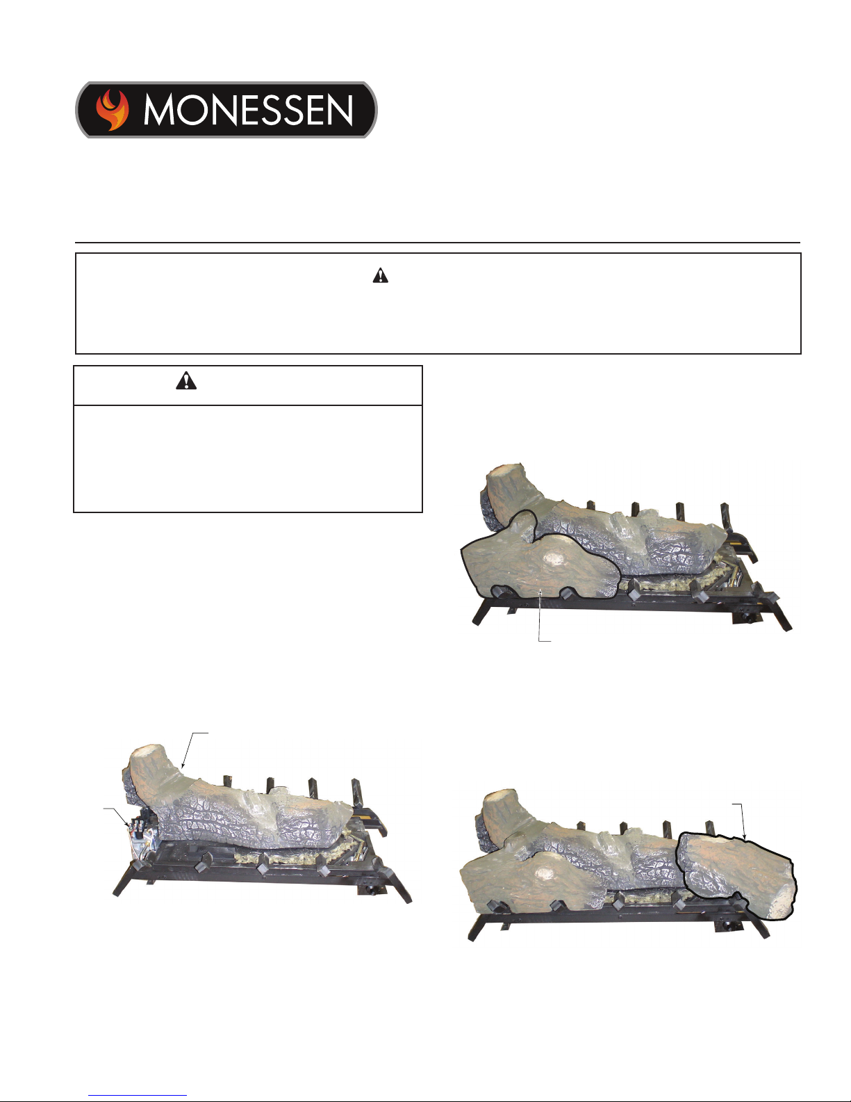
A. Log Placement
Begin on Side A, valve on left as you face the replace.
1. Place log #1 on burner by aligning two (2) holes on
bottom of log with two (2) pins on burner. The tallest
part of the log is on the valve side of burner. Gently
push log down until it comes in contact with burner surface. Figure 5.1
Log 1
2. Place log #2 on left grate tines by aligning the ‘V’
notches in the log with grate tines. The groove on the
bottom of the log should be rmly seated on the grate
bar. Figure 2
Log #2
Figure 2 - Place Log #2
3. Place log #3 on farthest right grate tine by aligning the
‘V’ notch in log with grate tine. The groove in the bottom of the log should sit on the ller bracket surround-
ing the pilot assembly. Figure 3
Control
Valve
Figure 1 - Place Log #1
Monessen • NBST27-F Log Placement Instructions • 4615-903 Rev. A • 08/18
Log #3
Figure 3 - Place Log #3
Page 2
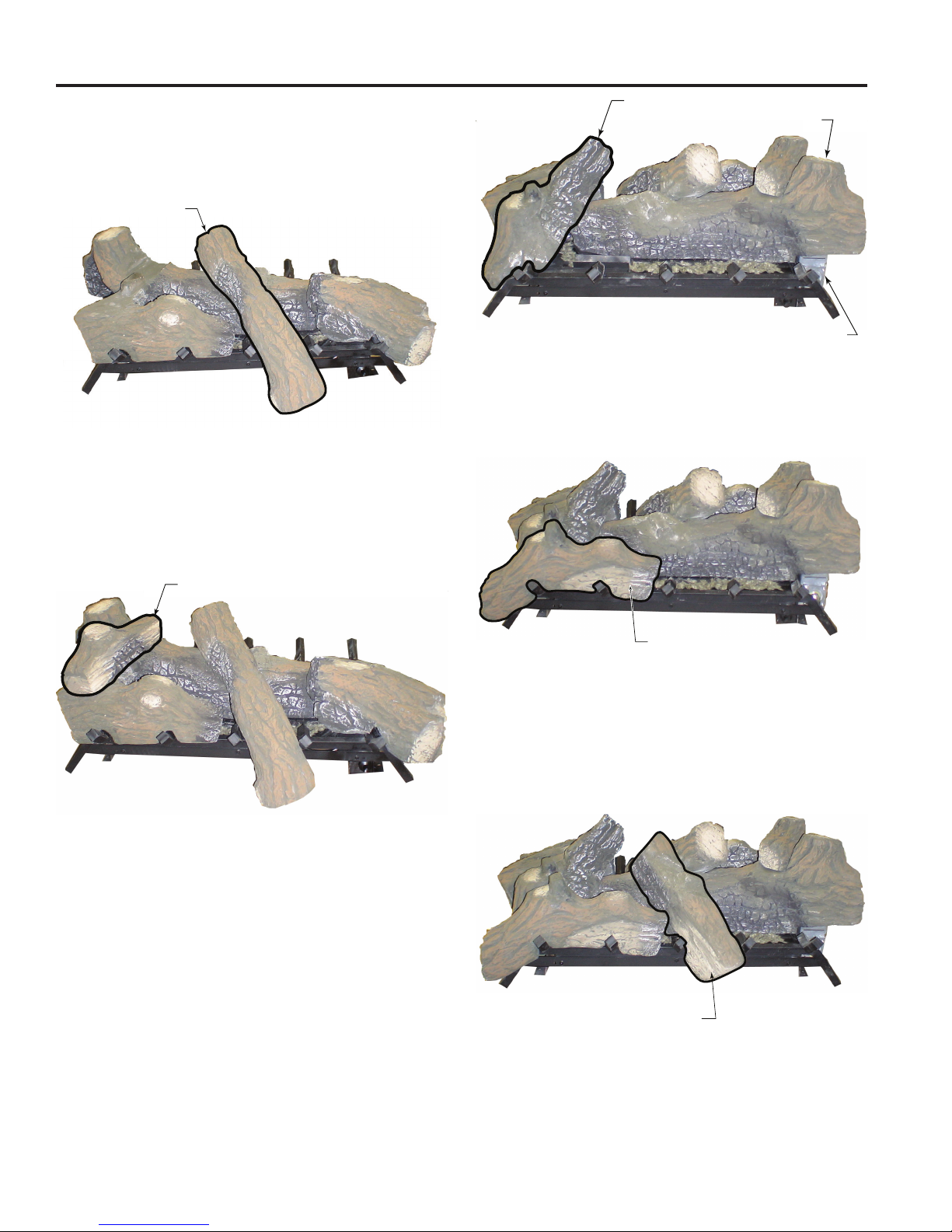
4. Place log #4 by aligning the ‘V’ notch on bottom of log
with horizontal grate bar between tines as shown in
Figure 20. Place the rectangular notch on bottom of
log onto the matching rectangular protrusion on log #1.
Figure 4
Log #4
Figure 4 - Place Log #4
5. Place log #5 by placing rectangular notch on bottom
of log onto matching rectangular protrusion on log #2.
Make sure ember or ‘burnt’ portion of log is facing center of burner. Figure 5
Log #6
Log #1
Control Valve
Figure 6 - Place Log #6
7. Place log #7 on left two (2) grate tines by aligning the
‘V’ notch in log with grate tines. Make sure groove on
bottom of log is rmly seated on grate bar. Figure 7
Log #5
Figure 5 - Place Log #5
Continue on Side B, valve on right as you face the
replace.
6. Place log #6 on pilot end of burner by aligning the ‘V’
notch in bottom of log with the ller bracket surrounding the pilot. Place the rectangular notch in the bottom
of the log onto the rectangular protrusion on the end of
log #1. Figure 6
Log #7
Figure 7 - Place Log #7
8. Place log #8 by aligning ‘V’ notch in bottom of log with
the horizontal grate bar between tines as shown in Fig-
ure 24. Place the rectangular notch on bottom of log
onto rectangular protrusion on middle of log #1. Figure
8
Log #8
Figure 8 - Place Log #8
2 Monessen • NBST27-F Log Placement Instructions • 4615-903 Rev. A • 08/18
Page 3

9. Place log #9 on farthest right grate tine by aligning ‘V’
notch in bottom of log with grate tine. Place rectangular notch in bottom of log onto rectangular protrusion
on log #8. Figure 9
Log #9
Figure 9 - Place Log #9
10. Place log #10 by aligning two (2) rectangular notches
on bottom of log with rectangular protrusions on logs
#6 & #7. Make sure the ember or ‘burnt’ area of log is
facing center of burner. Figure 10
DO NOT sprinkle volcanic rocks on the logs,
around the pilot, nor near the burners. This
may cause sooting. Place volcanic rocks
only on the oor of the replace.
During initial opearation of the new heater,
new burning logs and/or rock wool will give
CAUTION
off a paper burning smell and orange ames
will be present. Simply open the windows
for a few hours to vent the odor.
C. Flame Appearance
Flames from the pilot and burner should be visually
checked as soon as the heater is installed. In addition,
periodically check the ames visually during operation.
Check the Pilot Flame (refer to lighting instructions)
The pilot ame must always be present when the heater is
in operation. It should just touch the top of the thermocouple
tip for natural. Refer to Figure 11 for correct pilot ame.
If the pilot ame does not touch the thermocouple, then the
main burner cannot function reliably. Figure 12 for incorrect
shape of pilot ame.
Log #10
Figure 10 - Place Log #10
B. Place Decorative Rock
The volcanic rocks are shipped with your log set. The volcanic rocks may be placed around the unit on the oor of
the rebox. Be sure to avoid any areas on the burner itself
Thermocouple
for Natural
Thermocouple
for LP
Figure 10 - Correct Appearance of Pilot Flame
Thermocouple
for Natural
Thermocouple
for LP
Monessen • NBST27-F Log Placement Instructions • 4615-903 Rev. A • 08/18
Figure 11 - Incorrect Appearance of Pilot Flame
Page 4

In normal operation at full rate after 15 minutes, the
following ame appearances should be observed:
Burner will have a random pattern of yellow ames as
shown in Figure 12. There should be glowing embers on
the front burner. NOTE: The front ames and embers will
be an opaque orange color during the burn off time.
CAUTION: After a 15 minute pre-heat period, observe all
yellow ames to ensure there is no impingement with any
log. If any yellow ame is contacting any log, turn off log
set and allow to cool. Remove all logs and carefully rein-
stall following log placement instructions precisely. Relight
burner and check again for impingement of any ame on
log. If ame impingement cannot be eliminated, contact
your installer or dealer for assistance. Flame impingement
on logs may create soot and possible property damage.
D. Operating Insructions
Avoid any drafts that alter burner ame patterns. Do
not allow fans to blow directly into the replace. Do not
place a blower inside the burn area of the rebox. Ceiling
fans may create drafts that alter ame patterns. Sooting
and improper burning will result.
During manufacturing, fabricating and shipping, various
components of this appliance are treated with certain oils,
lms or bonding agents. These chemicals are not harmful,
but may produce annoying smoke and smells as they are
burned off during the initial operation of the appliance,
possibly causing headaches or eye or lung irritation. This
is a normal and temporary occurrence.
The initial break-in operation should last four hours with the
burner at the highest setting. Provide maximum ventilation
by opening windows or doors to allow odors to dissipate.
Any odors remaining after this initial break-in will be slight
and will disappear with continued use.
This appliance must not be used with glass doors in the
closed position. This can lead to pilot outages and severe
sooting outside the replace.
Figure 12 - Correct Appearance of Rear Flames
WARNING: This part is designed to be used with a product that operates with one of the
following fuel sources: liquid propane, natural gas, wood, or wood pellets. This product and
the fuel used to operate this product, and the products of combustion of such fuel, can expose
you to chemicals including benzene and carbon black which are known to the State of California to cause cancer, and carbon monoxide which is known to the State of California to cause
birth defects or other reproductive harm. For more information go to www.P65Warnings.ca.gov.
For a complete list of warn-ings and safety instructions for this product, download the Owner’s
Manual at www.hearthnhome.com
Monessen, a brand of Hearth & Home Technologies
7571 215th Street West, Lakeville, MN 50044
www.monessenhearth.com
Monessen • NBST27-F Log Placement Instructions • 4615-903 Rev. A • 08/18
 Loading...