

Page 1
– Do not store or use gasoline or other fl ammable
vapors and liquids in the vicinity of this or any
– WHAT TO DO IF YOU SMELL GAS
• Do not try to light any appliance.
• Do not touch any electrical switch; do not use
• Immediately call your gas supplier from a
• If you cannot reach your gas supplier, call the
fi re department.
– Installation and service must be performed by
WARNINGS
WARNINGS
WARNINGS
WARNINGS
Page 2

.................................
3
......................................................
.............................
Firebox External Dimensions
Minimum Hearth Dimensions
.................................
...............................................
..............................................
................................................
Forced Air Kit
.......................................................
Brass or Chrome Trim
Firebrick
...............................................................
Optional Wide Canopy
Warranty
..................................................
Page 3
the absence of local codes, with the
National Fuel Gas
box enclosures for gas-fi red unvented decorative room
heaters.
location of the heater, and annual cleaning are necessary
to avoid potential problems with sooting. Sooting,
resulting from improper installation or operation,
placement instructions for proper installation.
Candles, incense, oil lamps, etc. produce
these types of products. In addition, the smoke and/or
to minimize the use of candles, incense, etc. while the
vent-free appliance is in operation.
room in which it is installed. Provisions for adequate
installation guidelines.
Please leave these instructions with the owner.
Please retain these instructions for future reference
1. Due to high temperatures, the appliance should
be located out of traffi c and away from furniture
2. Children and adults should be alerted to the hazard
to avoid burns or clothing ignition.
3. Young children should be carefully supervised
4. Do not place clothing or other fl ammable material
5. Any safety screen or guard removed for servicing
the heater.
6. Installation and repair should be done by a qualifi ed
7. To prevent malfunction and/or sooting, an unvented
imperative that control compartments, burners and
Early signs of
headaches, dizziness and/or nausea. If you have these
for use with this heater where applicable.
WARNING
Page 4
They are not intended to be a primary heating appli-
In most homes of average construction, this does not pose
harmful but may produce annoying smoke and smells
irritation. This is a normal and temporary occurrence.
The initial break-in operation should last two to three
hours with the burner at the highest setting. Provide
maximum ventilation by opening windows or doors to
initial break-in period will be slight and will disappear
piping system by closing its equipment shutoff valve
to inspect the room heater and to replace any part of the
room heater is installed.
vent the fi rebox from coming in contact with combustible
materials.
www.nfi certifi ed.org
We suggest that our gas hearth
®
wellhead gas.
WARNING
Page 5
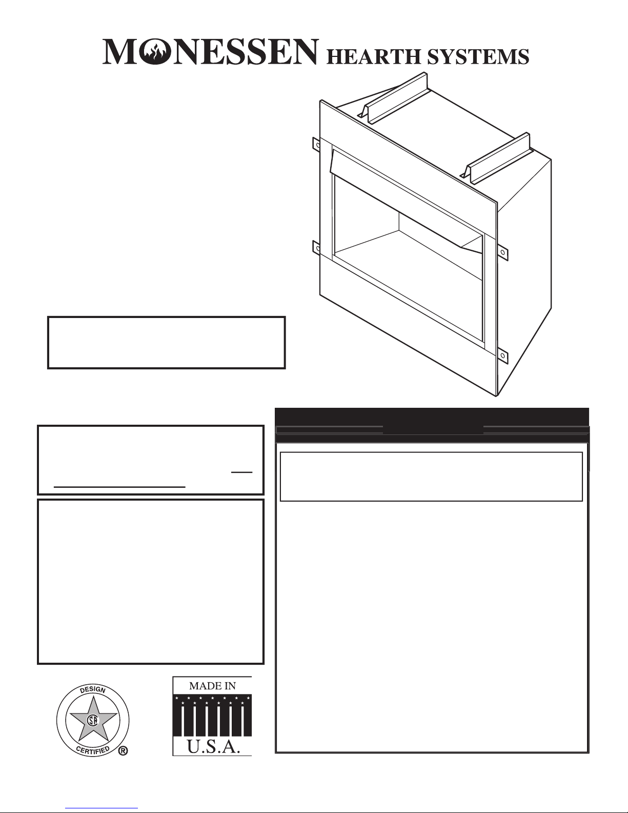
The MCUF36 and MCUF42 Series are vent-free fi reboxes. They feature a self contained heat-circulating system.
This installation manual will enable you to obtain a safe, effi cient and dependable installation of your vent-free fi rebox.
Do not alter or modify the fi rebox or its components under any circumstances. Any modifi cation or alteration of the fi rebox
1. Vent-Free Gas Firebox 4. Five (5) sheet metal screws for canopy
2. Canopy 5. Two (2) nuts and bolts for grate
3. Installation and Operating Instructions
WHAT YOU WILL NEED FOR INSTALLATION
Piping complying with local codes
• Wall fi nishing materials
Refer to the installation instructions provided with the log sets for items required for log set installation.
for the fi rebox.
WARNING
NOTICE
Page 6

D
F
E
H
63/4"
63/4"
261/2"
27"
21/2"
21/2"
1
/2"-5/8"
433/4"
40"
2" Knockout
95/8"
81/4"
C
B
A
In planning the installation for the appliance it is necessary to determine where the unit is to be installed and whether optional
installation. Each installation is unique, however, and might require a different sequence.
4. Install vent-free gas log heater per the instructions provided with the vent-free gas log heater.
B
C //
/
/
E
/4/
4
36" 42"
Page 7

AND
A
/2/
4
B
C //
D
vent-free fi rebox. The following factors should be taken
into consideration:
• Clearance to side wall, ceiling, woodwork and
page 8. Minimum clearances to combustibles
must
be maintained.
• Location must not be affected by drafts caused by
kitchen exhaust fans, ceiling fans, return air registers
• Installation must provide adequate ventilation and
•
DO NOT INSTALL THIS FIREBOX IN A BED-
ROOM OR BATHROOM.
• Location should be out of high traffi c or windy or
DO NOT INSTALL WHERE CURTAINS, FURNITURE, CLOTHING OR OTHER FLAMMABLE OBJECTS
ARE LESS THAN 42" FROM FRONT OF HEATER.
• Never obstruct the front opening of the vent-free fi rebox or restrict the fl ow of combustion and ventilation air.
• Minimize modifi cations to existing construction. Refer to Figure 3 below for location suggestions.
• Do not install in the vicinity where gasoline or other fl ammable liquids may be stored. The vent-free fi rebox must be
kept clear and free from these combustible materials.
Page 8

9"
Minimum
42"
Minimum
9"
Minimum
Ensure that minimum clearances shown in Figures 4 through 7 are maintained. Left and right clearances are determined
Follow these instructions carefully to ensure safe installation. Failure to follow these requirements may create a
Sidewall clearances:
The clearance from the inside of the appliance to any combustible wall should not be
less than 9".
See Figure 4.
Ceiling clearance:
The ceiling must be at least 42” from the top of the fi rebox opening.
See Figure 4.
Back wall clearnace:
The appliance may be placed against a combustible back wall.
AND
Page 9

/
AND
4.
Mantel clearances:
The canopy supplied with the unit must be installed. If a combustible mantel is installed, it must
meet the clearance requirements as shown in
Figure 5
see page 14
This inner chamber fi rebox fl oor must be installed at least 5" above any combustible fl ooring mate-
rial, such as carpeting or asphalt tile, which is closer than 14" to the base of the fi rebox.
See Figure 6.
The inner chamber fi rebox fl oor may be installed nearer to the fl oor if a minimum of 14" of noncombustible material
See Figure 7.
Page 10

H
G
D
F
E
A
C
B
A
81/4"
1
/2"-5/8"
C
A
G
C
G
Firebox framing can be built before or after the appliance is set in place. Construct fi rebox framing following
Figures 8
See Figure 1 on Page 6
The framing headers may rest on the top of the fi rebox standoffs.
The fi rebox may be installed directly on a combustible fl oor or raised on a platform of an appropriate height. When the
installed on a metal or wood panel extending the full width and depth of the enclosure.
A 41
/4/
4
B 43
/
/
C 30
/2/
2
D 15
/
/
E 71
/2/
2
F 35
/
/
G 21" 21"
H 50
/2/
2
WARNING
Page 11

K
J
MCUF36 MCUF42
with Trim with Trim
41
/
/
2. Slide the fi rebox into prepared framing or position fi rebox in its fi nal position and frame later.
3. Level the fi rebox by checking the top edge of the fi rebox. Shim if necessary.
4. Anchor fi rebox to the side framing members using 8d nails or other suitable fasteners.
See Figure 13.
5. The canopy must be installed for safe operation of the heater.
See page 13
for canopy installation details.
When fi nishing a custom cabinet, mantel, or other built-in enclosure,
the opening size to accommodate the fi replace with trim installed
is as follows:
full consideration to the clearance
this manual.
WARNING
Page 12

the latest edition of the National Fuel Gas Code ANSI Z223.1/NFPA54.
Remove the baseplate for ease of gas line installation. Remove three (3) screws along the front edge of the baseplate.
Remove four (4) screws which secure the baseplate to the combustion casing (two at rear and one along each side).
Replace baseplate prior to connecting gas line to heater. Consult heater installation and operating instructions for correct
installation of the heater into the fi rebox.
The
/
both sides of the fi rebox.
Install a
/
2
recessed fl ush into the wall or fl oor. The valve should be controlled by a removable valve key for safety.
An ANSI approved manual shut-off valve, union and plugged
/
upstream of the heater.
A sediment trap may be upstream of the heater to prevent moisture and contaminants from passing through trap to the heater
An external regulator must be used on all propane / L.P.G. heaters, in addition to the regulator fi tted to the heater,
to reduce the supply tank pressure to 13" w.c. (maximum). Any copper tubing used to supply propane / L.P.G. from
the tank must be internally tinned.
After completing connection, test all gas joints from the gas meter to the gas heater regulator for leaks. Using soap and
WARNING
WARNING
WARNING
Page 13

A canopy is furnished with each fi rebox and MUST be installed for safe operation.
See Figure 14.
1. Remove the three (3) screws from the top front frame assembly. Also remove the two (2) screws on the side frames.
See Figure 14.
2. Align the canopy with the holes in the top frame.
3. Replace the screws previously removed.
4. Tighten side screws. Make sure the canopy is level and
that may be provided with the unvented
WARNING
WARNING
Page 14

White
V.A.C.
If you are installing the forced air kit, Model BLOTM, on MCUF36 or MCUF42 models, see the installation instructions
provided with the kit for electrical wiring requirements, or the blower installation section. The fi rebox must be connected
to main power supply at time of fi rebox installation. The blower must be installed prior to the installation of the vent-free
heater. The electrical connections must be made before the fi rebox is framed and enclosed in the fi nished walls.
WARNING
Any of the original wire as supplied with the fi replace must
be replaced. Contact dealer for proper replacement wiring
harness.
Electrical power cord (plug) can be routed to exit the
MCUF36/MCUF42 on either the left side or the right side.
Remove cord protector from side of unit, route power cord
through hole opposite side. Reinstall cord protector.
you against electrical shock. Only connect plug to a properly grounded, three-prong
The optional wide canopy can be installed. See installation instructions provided with kit.
WARNING
WARNING
Page 15

ITEM DESCRIPTION QTY
1 Canopy 1 26D4568K 26D4570K
2 Screen Panel 2 26D4562 26D45622
3 Screen Rod 2 26D0132K 26D0133K
ACCESSORIES IN KITS
1 Standard Brass Canopy 1 BRCU36 BRCU42
1 Wide Brass Canopy 1 BRC36 BRC42
4 Blower w/ Rheostat 1 BLOTM BLOTM
5 Brass Trim Curved Design 1 BRTKM36 BRTKM42
5 Pewter Trim Curved Design 1 PWTKM36 PWTKM42
5
1 BLTKM36 BLTKM42
ITEM DESCRIPTION QTY
1 Canopy 1 26D4568K 26D4570K
2 Screen Panel 2 26D4562 26D45622
3 Screen Rod 2 26D0132K 26D0133K
ACCESSORIES IN KITS
1 Standard Brass Canopy 1 BRCU36 BRCU42
1 Wide Brass Canopy 1 BRC36 BRC42
4 Blower w/ Rheostat 1 BLOTM BLOTM
5 Brass Trim Curved Design 1 BRTKM36 BRTKM42
5 Pewter Trim Curved Design 1 PWTKM36 PWTKM42
5
Page 16

June 2004 P/N 26D4720 • Rev. 1
The following components are warranted for life to the original owner, subject of proof of purchase: Firebox,
The following components are warranted for 5 years to the original owner, subject of proof of purchase: Vent
Free Ceramic Fiber Logs, Catalytic Filter and Aluminized Burners.
Monessen Hearth Systems (MHS) warrants the components and materials in your gas appliance to be free from
manufacturing and material defects for a period of two years from date of installation. After installation, if any of
the components manufactured by MHS in the appliance are found to be defective in materials or workmanship,
MHS will, at its option, replace or repair the defective components at no charge to the original owner. MHS
two years from the date of installation. Any products presented for warranty repair must be accompanied
by a dated proof of purchase.
This Limited Lifetime Warranty will be void if the appliance is not installed by a qualifi ed installer in accordance
the installation thereof by unqualifi ed installers, (2) the costs of removal, reinstallation or transportation of
by an authorized service representative.
This warranty is expressly in lieu of other warranties, express or implied, including the warranty of merchantability
that do not allow limitations on how long an implied warranty lasts, or do not allow exclusion of indirect
MHS reserves the right to investigate any and all claims against the Limited Lifetime Warranty and decide
upon method of settlement.
For information about this warranty, contact:
Technical Services
Monessen Hearth Systems
149 Cleveland Drive
Paris, Kentucky 40361
 Loading...