

Monessen Hearth IRVF2T, IRVF3T, IRVF5T Maintance Manual
WARNING
WARNING
IRVF2T, IRVF3T, AND IRVF5T MODELS
INFRARED UNVENTED ROOM HEATERS
WITH THERMOSTAT CONTROL
INSTALLATION, OPERATION AND MAINTENANCE MANUAL
THE DESIGN OF THIS HEATER COMPLIES WITH STANDARD Z21.11.2 OF THE AMERICAN NATIONAL STANDARDS INSTITUTE AS
CERTIFIED
BY CSA INTERNATIONAL.
THIS APPLIANCE MAY BE INSTALLED IN AN AFTERMARKET, PERMANENTLY LOCA TED, MANUFACTURED (MOBILE) HOME,
WHERE NOT PROHIBITED BY LOCAL CODES.
THIS APPLIANCE IS ONLY FOR USE WITH THE TYPE OF GAS INDICATED ON THE RATING LABEL. THIS APPLIANCE IS NOT
CONVERTIBLE
FOR USE WITH OTHER GASES.
WARNING: IF THE INFORMATION IN THIS MANUAL IS NOT FOLLOWED EXACTLY, A FIRE OR EXPLOSION MAY RESULT
CAUSING
PROPERTY DAMAGE, PERSONAL INJURY OR LOSS OF LIFE.
DO NOT STORE OR USE GASOLINE OR OTHER FLAMMABLE VAPORS AND LIQUIDS IN THE VICINITY OF THIS OR ANY OTHER
APPLIANCE
.
WHA T TO DO IF YOU SMELL GAS
• DO NOT TRY TO LIGHT ANY APPLIANCE.
• DO NOT TOUCH ANY ELECTRICAL SWITCH; DO NOT USE ANY PHONE IN YOUR BUILDING.
• IMMEDIATELY CALL YOUR GAS SUPPLIER FROM A NEIGHBOR’S PHONE. FOLLOW THE GAS SUPPLIER’S
INSTRUCTIONS
.
• IF YOU CANNOT REACH YOUR GAS SUPPLIER, CALL THE FIRE DEPARTMENT.
INST ALLATION AND SERVICE MUST BE PERFORMED BY A QUALIFIED INSTALLER, SERVICE AGENCY OR THE GAS SUPPLIER.
THIS IS AN UNVENTED GAS-FIRED HEATER. IT USES AIR (OXYGEN) FROM THE ROOM IN WHICH IT IS INSTALLED. PROVISIONS
FOR
ADEQUATE COMBUSTION AND VENTILATION AIR MUST BE PROVIDED. REFER TO COMBUSTION AND VENTILATION
AIR REQUIREMENTS SECTION OF THIS MANUAL FOR DETAILS.
53D9012. Rev 1 03/03
TABLE OF CONTENTS
Your heater has been designed for years of safe, efficient, and trouble-free operation provided the
instructions in this manual are followed. To help insure your safety , it is very important that you take time
to read this entire manual before installing or operating this heater .
Important Information .................................................................................... ...... .. .. 1
Parts Diagram and List
How This Appliance Operates ..............................................................................4
Selecting A Location .........................
Gas Piping and Pressure Requirements
Combustion and Ventilation Air Requirements ........................................................9-10
Installation and Adjustment . .................................................................. .............. 11-15
Lighting and Operating Heater .................................................. ........................16-17
Safety Checklist ..............................................................................................18
Maintenance ......................................................................................................19
Troubleshooting ................................................................................ .. ...................20
Warranty ............................................................................................................21
•DUE TO HIGH TEMPERATURES, THE HEATER SHOULD BE LOCATED OUT OF TRAFFIC AND AWAY FROM
FURNITURE
•C
HILDREN AND ADULTS SHOULD BE ALERTED TO THE HAZARD OF HIGH SURFACE TEMPERATURE AND
SHOULD
•Y
OUNG CHILDREN SHOULD BE CAREFULLY SUPERVISED WHEN THEY ARE IN THE SAME ROOM WITH THE
HEATER
•D
O NOT PLACE CLOTHING OR OTHER FLAMMABLE MATERIAL ON OR NEAR THE HEATER.
•A
NY SAFETY SCREEN OR GUARD REMOVED FOR SERVICING THE HEATER MUST BE REPLACED PRIOR TO
OPERATING
•I
NSTALLATION AND REPAIR SHOULD BE PERFORMED ONLY BY A QUALIFIED SERVICE PERSON.
•T
HE HEATER SHOULD BE INSPECTED BEFORE USE AND CLEANED AND INSPECTED AT LEAST ANNUALLY BY
A
PROFESSIONAL SERVICE PERSON. MORE FREQUENT CLEANING MAY BE REQUIRED DUE TO EXCESSIVE
LINT
FROM CARPETING, BEDDING MATERIAL, ETC. IT IS IMPERATIVE THAT CONTROL COMPARTMENTS,
BURNERS AND CIRCULATING-AIR PASSAGEWAYS OF THE HEATER BE KEPT CLEAN.
•T
HIS APPLIANCE IS INTENDED FOR SUPPLEMENTAL HEATING.
F
OR MASSACHUSETTS RESIDENCES ONLY:
•T
HIS PRODUCT MUST BE INSTALLED BY A LICENSED PLUMBER OR GAS FITTER WHEN INSTALLED WITHIN
THE
COMMONWEALTH OF MASSACHUSETTS. FLEXLINE INSTALLATION MUST NOT EXCEED 36 INCHES.
AND DRAPERIES.
STAY AWAY TO AVOID BURNS OR CLOTHING IGNITION.
.
THE HEATER.
......................................................................................2-3
........................................... .........................5-6
..................................................................7-8
CAUTION
WARNING: ANY CHANGE TO THIS HEATER OR ITS CONTROLS CAN BE DANGEROUS.
WARNING: FAILURE TO KEEP THE PRIMARY AIR OPENINGS OF THE BURNERS CLEAN MAY RESULT IN
SOOTING
53D9012. Rev 1 03/03
AND PROPERTY DAMAGE.
IMPORTANT INFORMATION
EQUIPPED WITH
Study these instructions carefully before beginning the installation of
this heater. These instructions contain information to be used as a guide
during the installation and use of this heater. Critically important safety
information is provided in gray blocks along the edges of many pages.
These instructions must be followed for safe, efficient, and trouble-free
operation of this heater.
Before installing the heater, inspect it thoroughly for shipping damage
and missing parts. If any damage or missing parts are detected, report
this to the dealer from whom you purchased the heater and get the
deficiency corrected before installing and using the heater. Do not install
or use a damaged or incomplete heater.
The installer of this heater must describe the operation of the heater to
the people who will be operating it and leave this instruction manual with
the operator of the heater.
Do not use this room heater if any part has been under water. Immediately
call a qualified service technician to inspect the room heater and to
replace any part of the control system and any gas control which has
been under water.
2
Danger: This heater, as any gas-
fired appliance, can produce
poisonous carbon monoxide
along with other combustion
products. Carbon monoxide, in
strong concentrations, can
cause sickness, serious
personal injury and death.
Early signs of carbon monoxide
poisoning resemble the flu, with
headache, dizziness and/or
nausea. If you have these signs,
the heater may not be working
properly . Get fresh air at once!
Immediately have heater
serviced by a qualified
technician.
When properly installed, used and maintained, this heater should not
produce carbon monoxide in dangerous quantities. However, since
carbon monoxide can be deadly poisonous, the installer and all users of
this heater should read and follow these instructions carefully.
The type gas this heater is equipped for, and the only type gas supply it
should be attached to, is specified on a label affixed to the heater’s left
side reflector located just behind the cabinet front. An additional label
indicating the correct gas type is affixed to the bottom of the heater .
The input rating in Btu/hr for each of the heaters described by this manual
is as specified below in Table 1.
TABLE 1
MODEL
NUMBER
OF
HEATER
NUMBER
OF BURNER
PLAQUES
IN HEATER
BTU/HR INPUT
FOR HEATERS
EQUIPPED WITH
LP GAS
BTU/HR INPUT
FOR HEATERS
EQUIPPED WITH
NATURAL GAS
10,00010,0002IRVF2T
18,00015,0003IRVF3T
30,00025,0005IRVF5T
Some people (pregnant
women, persons with heart or
lung disease, anemia, those
under the influence of alcohol,
those at high altitudes) are
more affected by carbon
monoxide than others.
Danger: Operation of this heater
on gases for which it is not
equipped may lead to carbon
monoxide poisoning.
Warning: This heater cannot be
converted to a gas other than the
type for which it was equipped
at the factory .
Warning: Any change to this
heater or its controls can be
dangerous.
WARNING: DO NOT ALLOW FANS TO BLOW DIRECTLY INTO THE
FIREPLACE
BURNER
. AVOID ANY DRAFTS THAT ALTER
FLAME PATTERNS.
1
53D9012. Rev 1 03/03
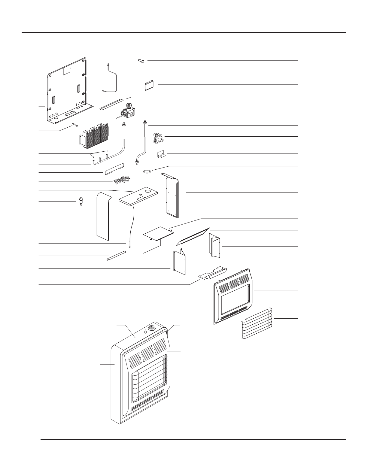
PARTS DIAGRAM
8 11 IN WC
555
FRONT
RIGHT
SIDE
LEFT
SIDE
TOP
5
16
17
18
19
20
21
22
23
24
25
26
27
28
29
TOP
LEFT
SIDE
RIGHT
SIDE
FRONT
30
2
53D9012. Rev 1 03/03

PARTS LIST
6
All repair part orders should be placed through your local dealer. To ensure prompt and accurate service, please
provide the following information when placing a repair part order: Model number of your Appliance, Part Name,
Part Number, and Quantity of parts needed. D
SELLER.
THE
O NOT TAKE A HEATER NEEDING REPAIR, OR BELIEVED TO BE DEFECTIVE, BACK TO
KEY
NO.
1
2
3
4
5
6
7
8
9
10
11
12
13
14
15
16
17
18
19
20
21
22
23
24
25
26
27
28
29
30
DESCRIPTION
Cabinet Back Pntd.
Speed Nut 10-24 U Type
Clamp, Thermostat Bulb
Burner Assembly
Orifice (LP Gas)
Orifice (Nat Gas)
Burner Tube Assembly
Venturi Shield
Pilot (LP Gas)
Pilot (NAT Gas)
Cabinet Top w/Caution Label
Piezo Ignitor
Cabinet Side Left W/Labels
Piezo Cable
Brace Reflector
Reflector, Left Side Pntd.
Front Shield & Hearth Plate Assembly
Wall Anchor
Pilot Tube Assembly
Control Bracket Assembly Pntd.
Burner Shield
Thermostat Control
Regulator To Control Tube Assembly
Regulator (LP Gas)
Regulator (NAT Gas)
Regulator Bracket
Control Ring
Cabinet Side Right W/Markings
Heat Shield Weld Assembly
Deflector Pntd.
Reflector, Right Side Pntd.
Cabinet, Front Pntd.
Dress Guard
QTY. PER
HEATER
1
4
2
1
see ( )
see ( )
1
1
1
1
1
1
1
1
1
1
1
2
1
1
1
1
1
1
1
1
1
1
1
1
1
1
1
IRVF2T
PART NO.
077519
050889
P549
072285
072085 (2)
072084 (2)
072420
058711
14D0476
26D2529
074034
071040
078074
067972
049863
069104
074039
052997
072419
054461
055878
072090
072425
072088
072086
071705
051041
078073
075278
069103
072330
072334
IRVF3T
PART NO.
077520
050889
P549
072286
072085 (3)
072084 (3)
072422
055872
14D0476
26D2529
074035
071040
078074
067972
069104
074040
052997
072421
054461
055873
072090
072425
072088
072087
071705
051041
078073
055870
075279
069103
072337
072341
IRVF5T
PART NO.
078040
050889
P549
072287
072085 (5)
072084 (5)
072424
055874
14D0476
26D2529
074036
071040
078074
067972
069104
074041
052997
072423
054461
055875
072090
072425
072088
072087
071705
051041
078073
050980
075280
069103
072344
072348
3
53D9012. Rev 1 03/03

HOW THIS APPLIANCE OPERATES
This heater is to be installed either wall mounted or freestanding
Warning: This heater is hot while
in operation. Do not touch. Keep
children, clothing and furniture
away . Never operate this heater
without the factory-installed
dress guard in place. Never use
this heater to dry clothes, cook
on, or for any other purpose other
than providing heat to the area
around the heater .
Notice: The heater will go
through a curing process during
its initial (first 2 to 3 hours)
operating period and may emit
some smoke and fumes (burning
off oil, etc.). Be prepared for any
smoke and fumes by raising
windows or opening doors to
provide additional ventilation
during this initial operating
period.
according to these instructions and must not be enclosed within a
confined space or within a cabinet. It is intended to provide heat directly
to the space in which it is located. The heater is designed, tested and
built to operate safely , when installed according to these instructions, in
areas built of material common to residential construction. Any alteration
of the heater or any installation and use not in accordance with these
instructions may be hazardous. Refer to "
COMBUSTION AND VENTILATION AIR REQUIREMENTS" sections of this manual
"
for details.
The heater’s burner plaques produce heat as soon as they are lit. During
operation, the heater gives off infrared radiant heat which travels through
the air and heats nearby objects first, then heats the room air.
The control system on this heater is a safety system that must not be
tampered with. Do not attempt to make any adjustments to the control
or pilot other than those described in the "
or "TROUBLESHOOTING" sections of this manual.
The control system on this heater serves several functions. It regulates
the incoming gas to the correct pressure for the combustion rate required.
It will not regulate LP gas directly from the container; a separate regulator
must be installed on the tank or bottle to reduce the gas pressure supplied
to the heater to between 11 and 13 inches water column. The control
system also provides a safety shutoff to allow gas to flow to the burner
assembly only when the pilot is burning and to shut off gas to both the
pilot and burner assembly should the pilot flame not be burning. The
control system provides a manual valve to turn gas on and off to the
burner assembly . The control has a thermostat which automatically shuts
off the burner assembly when the room reaches a selected temperature.
There is a safety feature in the control valve which will lock the control
knob in the ‘Off’ position until the pilot valve closes, should the control
knob be accidentally turned to ‘Off’ while the pilot is burning; this prevents
escape of unburned gases. The control system also regulates the pilot
gas flow as required for proper operation and provides for shutoff of the
gas to the pilot and burner assembly before the oxygen in the area of the
heater is depleted to dangerous levels.
SELECTING A LOCATION" and
INSTALLATION AND ADJUSTMENT"
4
53D9012. Rev 1 03/03
Air is pulled into the burner assembly by the gas stream and mixed with
the gas inside the burner assembly before burning. Additional air required
to complete the burning of the gas enters the heater through its front.
See the “
this manual. Blocking or altering air flow into and away from the heater
could cause improper combustion and the production of carbon monoxide
gas that could accumulate to hazardous concentrations. To prevent a
disruption of the air flow through the heater, keep the heater clean as
described by the “
COMBUSTION AND VENTILATION AIR REQUIREMENTS” section of
MAINTENANCE” section of this manual.
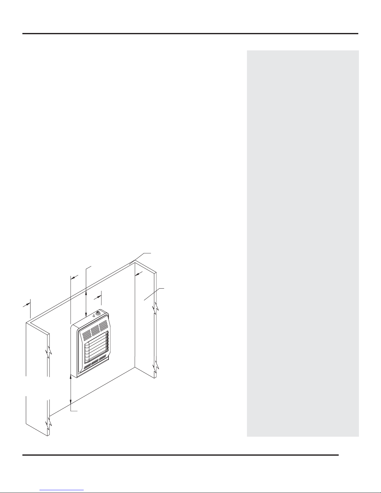
SELECTING A LOCATION
36" MIN.
(SEE NOTE 2 )
18" MIN.
(SEE NOTES
1 &2 )
12" MIN.
(SEE NOTES
1 &2 )
NOTES:
1. THE 12" MINIMUM AND 18"
MINIMUM DIMENSIONS
FROM HEATER SIDES TO
COMBUSTIBLES MAY BE
REVERSED IF NECESSARY.
2. WALL MOUNTED HEATER
SHOWN. UNLESS NOTED
OTHERWISE, ALL CLEARANCE
DIMENSIONS SHOWN ALSO
APPLY TO A HEATER MOUNTED
ON A FLOOR STAND.
3. GAS PIPING NOT SHOWN.
(SEE NOTE 2)
IN FRONT OF HEATER.
MATERIAL CLOSER THAN 48 INCHES
DO NOT PLACE COMBUSTIBLE
SIDE WALL
OR OTHER
COMBUSTIBLE
SURFACE
SIDE WALL
OR OTHER
COMBUSTIBLE
SURFACE
3"
MINIMUM TO TOP SURFACE OF
CARPETING, TILE OR OTHER
COMBUSTIBLE MATERIAL.
(APPLIES TO ALL WALL MOUNTED HEATERS ONLY)
CEILING LINE OR OTHER
COMBUSTIBLE SURFACE
These heaters are shipped from the factory equipped for mounting on a
flat wall. A wall-mount template is provided with each heater to aid in
locating the heater on a wall. Maintaining at least the minimum spacing
to combustibles as illustrated by Figure 1 is required for safety. Using
the wall-mount template will help ensure that the required minimum
clearances between the heater and adjacent walls, floor, and ceiling are
maintained when mounting the heater on a wall.
The wall-mount anchors provided with each heater are for mounting the
heater to a hollow wall (wall area between studs.) If the heater is to be
mounted to a solid wall such as concrete or masonry , these wall-mount
anchors should not be used. Obtain appropriate solid wall-mount anchors
with number 10 mounting screws from your local hardware store.
The minimum clearances (see Figure 1) between combustible materials
and a wall mounted heater are:
Back - 0 inches (mount directly on wall).
Floor - 3 inches
Sides - 12 inches on one side of the heater;
18 inches on the opposite side of the heater.
Top - 36 inches
Danger: Do not install this
heater in any area where
gasoline or any combustible or
explosive material will be used
or stored. The flame from this
heater is exposed to the area
around the heater. Contact with
explosive or flammable
materials will lead to explosion
or fire.
Front - 48 inches
36" MIN.
FIGURE 1
12" MIN.
(SEE NOTES
1 &2 )
SIDE WALL
OR OTHER
COMBUSTIBLE
SURFACE
(APPLIES TO ALL WALL MOUNTED HEATERS ONLY)
(SEE NOTE 2 )
18" MIN.
(SEE NOTES
1 &2 )
3"
MINIMUM TO TOP SURFACE OF
CARPETING, TILE OR OTHER
COMBUSTIBLE MATERIAL.
CEILING LINE OR OTHER
COMBUSTIBLE SURFACE
SIDE WALL
OR OTHER
COMBUSTIBLE
SURFACE
NOTES:
1. THE 12" MINIMUM AND 18"
MINIMUM DIMENSIONS
FROM HEATER SIDES TO
COMBUSTIBLES MAY BE
REVERSED IF NECESSARY.
2. WALL MOUNTED HEATER
SHOWN. UNLESS NOTED
OTHERWISE, ALL CLEARANCE
DIMENSIONS SHOWN ALSO
APPLY TO A HEATER MOUNTED
ON A FLOOR STAND.
3. GAS PIPING NOT SHOWN.
DO NOT PLACE COMBUSTIBLE
MATERIAL CLOSER THAN 48 INCHES
IN FRONT OF HEATER.
(SEE NOTE 2)
5
53D9012. Rev 1 03/03

SELECTING A LOCATION
Danger: Operation of the heater
as a freestanding heater without
the proper floor stand correctly
installed may lead to fire or the
production of carbon monoxide
gas.
Warning: If heater is installed and
operated at clearances less than
those specified as minimum in
these instructions, a fire hazard
may exist with possible fire
causing property damage or
personal injury. If the heater is
operated at clearances less than
those specified in these
instructions, insufficient air may
be supplied to the heater causing
poisonous carbon monoxide to
be produced.
Notice: The Z21.1 1.2 standard of
the American National Standards
Institute prohibits the installation
of a heater with a rating greater
than 6,000 Btu’s per hour in a
bathroom. The standard also
prohibits the installation of a
heater with a rating greater that
10,000 Btu’s per hour in a
bedroom.
Warning: Failure to adequately
protect the flooring materials
under a floor mounted heater can
lead to damaged flooring material
or fire.
A floor stand model XFS is available from your dealer. The floor stand
enables these heaters to be installed freestanding as shown by Figure
2.
The minimum clearances (see Figure 1) between combustible material
and a freestanding heater installed on a floor stand are:
Back - 0 inches (floor stand may touch rear wall)
Floor - 0 inches (floor stand may rest directly on floor - See "
FLOOR
PROTECTION" information below.)
Sides - 12 inches on one side of the heater;
18 inches on the opposite side of the heater.
Top - 36 inches
Front - 48 inches
When selecting a location for the heater, be sure attention is given to
the following considerations.
1. Some materials such as vinyls and plastics will deform at relatively
low temperatures and must be kept at greater clearance distances
than the minimum clearances specified above.
2. The heater should be located centrally within the area where heat
is desired, but out of traffic areas, or areas where children play, to
minimize the chance of persons accidentally contacting the hot
surface of the heater.
3. The heater must not be located near doorways or in other areas
where drafts may affect the operation of the pilot or burner assembly .
4.
DO NOT INSTALL THE HEATER BENEATH CURTAINS OR DRAPES.
To comply with the Z21.11.2 standard of the American National
Standards Institute, none of the heaters described by this manual
may be installed in a bathroom and the IRVF2T is the only model
that may be installed in a bedroom. If an infrared heater is installed
in a bedroom, it must be wall mounted. Floor stand mounted heaters
are prohibited in bedrooms.
FLOOR PROTECTION
Some Flooring materials will discolor or otherwise deteriorate due to
the temperature underneath the heater. Therefore, when the heater is
installed freestanding with a floor stand in place on carpet, tile, linoleum
or any combustible material other than wood flooring, the heater must
be installed with a wood panel, metal panel or stoveboard extending at
least the full width and depth of the floor stand. See Figure 2.
6
53D9012. Rev 1 03/03
 Loading...