

Monessen Hearth GG18PV, GG18NV, GG24NV, GG24PV User Manual
1
Monessen • Glow Getter Owner’s /Installation Manual • 4606-900 Rev. A • 8/17
Models:
Installation/Owner’s Manual
Appliance Setup, Care and Operation
NOTICE: DO NOT discard this manual!
In the Commonwealth of Massachusetts installation must be
performed by a licensed plumber or gas tter.
See appliance installation manual for additional
Commonwealth of Massachusetts requirements.
INSTALLER: Leave this manual with party responsible for use and operation.
OWNER: Retain this manual for future reference.
Contact your dealer with questions regarding installation, operation or service.
• DO NOT store or use gasoline or other am-
mable vapors and liquids in the vicinity of this
or any other appliance.
• What to do if you smell gas
- DO NOT try to light any appliance.
- DO NOT touch any electrical switch. DO
NOT use any phone in your building.
- Leave the building immediately.
- Immediately call your gas supplier from
a neighbor’s phone. Follow the gas supplier’s instructions.
- If you cannot reach your gas supplier, call
the re department.
• Installation and service must be performed
by a qualied installer, service agency, or the
gas supplier.
WARNING:
FIRE OR EXPLOSION HAZARD
Failure to follow safety warnings exactly
could result in serious injury, death, or
property damage.
GG18NV/PV
GG24NV/PV
Glow Getter
Series
• DO NOT install this unit in a bedroom or
bathroom.

Monessen • Glow Getter Owner’s /Installation Manual • 4606-900 Rev. A • 8/172
Safety Alert Key:
• DANGER! Indicates a hazardous situation which, if not avoided will result in death or serious injury.
• WARNING! Indicates a hazardous situation which, if not avoided could result in death or serious injury.
• CAUTION! Indicates a hazardous situation which, if not avoided, could result in minor or moderate injury.
• NOTICE: Used to address practices not related to personal injury.
Table of Contents
Installation Standard Work Checklist ....................3
1 Product Specic & Important Safety Information
A. Appliance Certication ............................4
B. BTU Specications ...............................4
C. High Altitude Installations ..........................4
D. Non-Combustible Materials Specication. . . . . . . . . . . . . . 4
2 Getting Started
A. Design and Installation Considerations ............... 5
B. Tools and Supplies Needed ........................ 5
C. Inspect Appliance and Components ..................5
D. Check Parts ....................................6
E. Installation Information ............................ 6
F. Millivolt Ignition Controls. . . . . . . . . . . . . . . . . . . . . . . . . . . 7
G. Pilot/ODS ......................................7
H. Adequate Combustion Ventilation Air .................8
3 Clearances & Height Requirements
A. ..............................................9
4 Gas Information
A. Gas Line Connection ............................15
B. Millivolt Valve Controls ...........................15
C. Fuel Type .....................................16
D. Gas Pressure ..................................16
E. Gas Service Access .............................16
F. Connect Optional Wall Switch or Thermostat ..........17
G. Connect Remote Receiver ........................18
H. Check System Operation .........................18
5 Gas Log Sets
A. Log Placement (Charisma). . . . . . . . . . . . . . . . . . . . . . . . 20
B. Log Placement (Moxie) .......................... 21
C. Flame Appearance ..............................23
6 Owner’s Manual
A. Congratulations ................................ 25
B. Limited Lifetime Warranty .........................26
7 Important Safety & Operating Information
A. Appliance Safety ............................... 28
B. General Operating Parts ......................... 30
C. Fuel Specications ..............................30
D. Before Lighting Appliance. . . . . . . . . . . . . . . . . . . . . . . . . 30
8 Product Specication Information
A. Application Certication ..........................31
B. BTU SPecications. . . . . . . . . . . . . . . . . . . . . . . . . . . . . . 31
9 Lighting Instructions
A. .............................................32
10 Maintenance & Service
A. Maintenance: Frequency & Tasks ................. 35
B. Maintenance Tasks: Qualied Service Technician .....35
C. Burner Ignition & Operation .......................36
D. Cleaning & Servicing ............................ 36
11 Troubleshooting
A. .............................................37
12 Service Parts & Accessories
A. Service Parts .................................. 38
B. Accessories ................................... 46
C. Contact Information ............................. 48
3
Monessen • Glow Getter Owner’s /Installation Manual • 4606-900 Rev. A • 8/17
Installation Standard Work Checklist
Gas Section 4 (Pg 15)
Proper appliance for fuel type.
Leak check performed and inlet pressure verified.
Verified proper air shutter setting for installation type.
Customer:
Lot/Address:
Model
(circle one): GG18NV/PV, GG24NV/PV
Date Installed:
Location of Fireplace:
Installer:
Dealer/Distributor Phone #
Serial #:
Comments: Further description of the issues, who is responsible (Installer/ Builder/ Other Trades, etc) and corrective
action needed _____________________________________________________________________________________
Comments Communicated to party responsible ____________________ by ______________________on ___________
(Builder / Gen. Contractor/) (Installer) (Date)
?YHW , ON F I SEY
___________________________
___________________________
___________________________
___________________________
___________________________
Gas Log Install Sections 2 and 4 (Pg. 5 & 20)
Verified that the chimney has been cleaned. (pg. 13)
Verifi ed clearances to combustibles.
Gas Logs are level
ed and secured.
See page 8 for adequate provisions for combustion and ventilation
air have been verified.
___________________________
___________________________
___________________________
___________________________
___________________________
Finishing Section 3 (Pg 9)
Verifi ed all clearances meet installation manual requirements.
Mantels and wall projections comply with installation manual requirements.
___________________________
___________________________
___________________________
___________________________
___________________________
Manual bag and all of its contents are removed and the log set
given to party responsible for use and operation.
Started log set and veried no gas leaks exist.
___________________________
___________________________
4606-903A 08/17
= Contains updated information.
Hearth & Home Technologies recommends the following:
• Photographing the installation and copying this checklist for your file.
• That this checklist remain visible at all times on the appliance until the installation is complete.
This standard work checklist is to be used by the installer in conjunction with, not instead of, the instructions contained in this
installation manual.
WARNING! Risk of Fire or Explosion! Failure to install appliance according to these instructions could
lead to a fire or explosion.
ATTENTION INSTALLER:
Follow this Standard Work Checklist
Embers & Logs Section 5 (Pg 20-23)
All packaging and protective materials removed (inside & outside of appliance).
Embers and logs installed correctly.
Accessories installed properly.
Electrical Section 4 (Pg 17)
Switch wires properly installed.
Monessen • Glow Getter Owner’s /Installation Manual • 4606-900 Rev. A • 8/174
This product is listed to ANSI standards for "Unvented
Room Heaters” and applicable sections of "Gas Burning
Heating Appliances for Manufactured Homes" and "Gas
Fired Appliances for Use at High Altitude."
A. Appliance Certication
D. Non-Combustible Materials Specication
Material which will not ignite and burn. Such materials are
those consisting entirely of steel, iron, brick, tile, concrete,
slate, glass or plasters, or any combination thereof.
Materials that are reported as passing ASTM E 136,
Standard Test Method for Behavior of Materials in
a Vertical Tube Furnace at 750 ºC shall be considered
non-combustible materials.
NOT INTENDED FOR USE AS A PRIMARY HEAT SOURCE.
This appliance is tested and approved as either supplemental room heater or as a decorative appliance. It should not
be factored as primary heat in residential heating calcula-
tions.
NOTICE: This installation must conform with local codes.
In the absence of local codes you must comply with the
National Fuel Gas Code, ANSI Z223.1-latest edition in
the U.S.A.
1
Product Specic and Important Safety Information
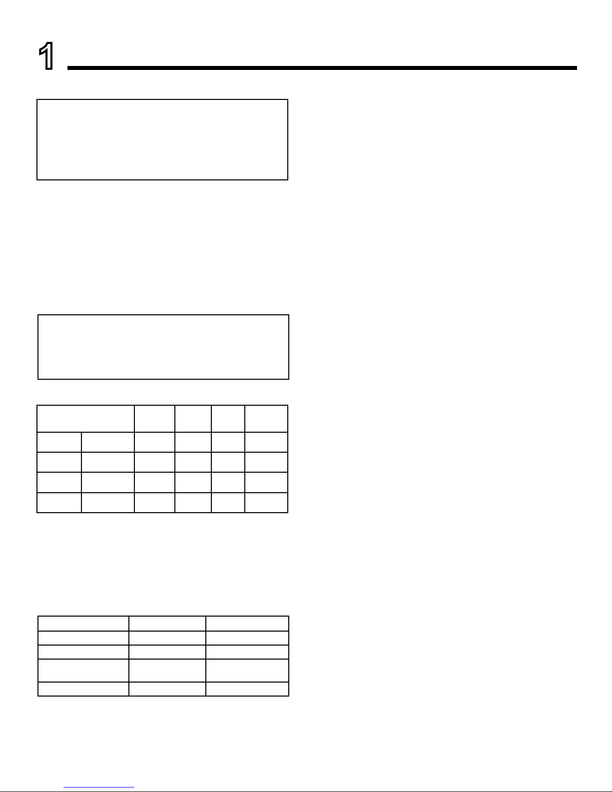
B. BTU Specications
C. High Altitude Installations
NOTICE: If the heating value of the gas has been reduced,
these rules do not apply. Check with your local gas utility
or authorities having jurisdiction.
When installing above 4500 feet elevation: Reduce input
rate 4% for each 1000 feet above 4500 feet.
Check with your local gas utility to determine proper
orice size.
MODEL: GG18NV/PV, GG24NV/PV
LABORATORY: CSA
TYPE: Unvented Room Heater
STANDARD: ANSI Z21.11.2-2016 (Unvented Application)
ANSI Z21.60-2012/CSA2.26-2012 (Vented
Application)
Models
Maximum
Input
BTU/h
Minimum
Input
BTU/h
Front
Orice)
Rear Orice
GG18NV (0-4500 FT) 29,000 21,000 #51 #46
GG18PV (0-4500 FT) 29,000 22,500 #60 1.35mm
GG24NV (0-4500 FT) 37,000 27,000 1.8mm 2.5mm
GG24PV (0-4500 FT) 37,000 29,000 #57 #53
GAS PRESSURES
NOTE: For LP models an external regulator is required
to reduce supply pressure to a maximum of 13" w.c.
NATURAL PROPANE (LP)
Inlet Minimum 5.0" w.c. 11.0" w.c.
Inlet Maximum 10.5" w.c. 13.0" w.c.
Gas Valve Manifold
Pressure Setting
3.5" w.c. 10" w.c.
Pilot Regulator 3.5" w.c. —
NATURAL GAS: An external regulator is required to reduce
supply pressure to a maximum of 101⁄2" w.c. on natural gas
systems operating at higher pressure.
PROPANE/LPG: An external regulator is required to reduce
supply pressure to a maximum of 13" w.c.
Millivolt Ignition Controls
The piezo ignitor allows ignition of the pilot without the use
of matches or batteries.
Millivolt control has four (4) positions:
OFF:All gas to the gas logs is shut off at the valve.
IGN : Valve position to light/maintain a standing pilot.
ON: Valve position to turn ON/OFF log set with remote
switch/thermostat.
LOW/HI: Variable position to control ame height (heat
output).
Pilot/ODS
The gas log heater is tted with a specially designed safety
pilot (ODS assembly) which senses the amount of oxygen
available in the room and shuts the gas log heater off if the
oxygen level begins to drop below a satisfactory level. The
pilot can only be relit when adequate fresh air is available.
Thermal Generator
The millivolt gas log pilot is tted with a millivolt (thermopile)
generator to provide power for remote activation.
5
Monessen • Glow Getter Owner’s /Installation Manual • 4606-900 Rev. A • 8/17
2
Getting Started
A. Design and Installation Considerations
Installation MUST comply with local, regional, state and
national codes and regulations. Consult insurance carrier,
local building inspector, re ofcials or authorities having
jurisdiction over restrictions, installation inspection and
permits.
Before installing, determine the following:
• Where burner assembly and log set are to be installed.
• Gas supply piping.
• Whether optional accessories—devices such as a wall
switch or remote control—are desired.
• Approved wood burning masonry replace or vent-free
replace.
Improper installation, adjustment, alteration, service or
maintenance can cause injury or property damage. For
assistance or additional information, consult a qualied
service technician, service agency or your dealer.
Installation and service of this appliance should
be performed by qualied personnel. Hearth
& Home Technologies recommends HHT
Factory Trained or NFI certied professionals.
C. Inspect Appliance and Components
• Carefully remove the appliance and components from
the packaging.
• Logs are packaged and sold separately.
• Report to your dealer any parts damaged in shipment.
• Read all of the instructions before starting the instal-
B. Tools and Supplies Needed
Before beginning the installation be sure that the following
tools and building supplies are available.
• Tape measure
• Gloves
• Voltmeter
• Manometer
• Phillips screwdriver
• Safety glasses
• Flat blade screwdriver
• Soapy water solution for gas leak testing
• Electric drill and bits (1/4 in. magnetic)
• External regulator (for propane/LPG only & 1/2 psi
Natural gas system
• Piping which complies with local codes
• Pipe sealant approved for use with propane/LPG
(Resistant to sulfur compounds)
Hearth & Home Technologies disclaims any responsibility
for, and the warranty will be voided by, the following actions:
• Installation and use of any damaged appliance.
• Modication of the appliance.
• Installation other than as instructed by Hearth & Home
Technologies.
• Installation and/or use of any component part not approved
by Hearth & Home Technologies.
Any such action may cause a re hazard.
WARNING! Risk of Fire, Explosion or Electric Shock!
DO NOT use this appliance if any part has been under
water. Call a qualied service technician to inspect the
appliance and to replace any part of the control system
and/or gas control which has been under water.
• Manual shutoff valve
• Sediment trap
• Tee joint
• Pipe wrench
lation. Follow these instructions carefully during the
installation to ensure maximum safety and benet.
WARNING! Risk of Fire or Explosion! Damaged parts
could impair safe operation. DO NOT install damaged, incomplete or substitute components. Keep appliance dry.
Gloves are recommended when handling
refractory to prevent skin irritation from
loose bers. Logs are fragile; handle with
care.
CAUTION
Monessen • Glow Getter Owner’s /Installation Manual • 4606-900 Rev. A • 8/176
E. Installation Information
Use manufacturer's installation and clearance require-
ments as dened in their manual.
The GG18, 24, 30 series unvented room heaters are
approved for installation into the following unvented reboxes: MCUF, LCUF, GCUF, GRUF, BUF and Exacta.
The Glow Getter Series unvented room heaters may also
be installed into a Ventless Firebox Enclosure for Gas Fired
Decorative Type Unvented Room Heaters per ANSI Z21.91
(typically referred to as a "universal rebox"), as long as
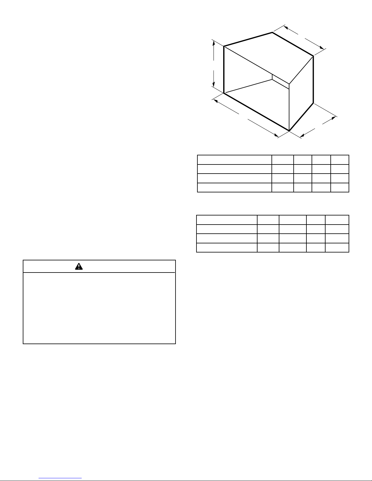
rebox hearth dimensions meet the minimum hearth dimensions shown below.
A
C
D
B
Figure 2.1 - Dimensions for Engine, Logs & Firebox
Model A B C D
GG18 with LOGS 25” 13" 20” 12"
GG24 withLOGS 29” 13" 24” 13”
GG30 with LOGS 32” 13” 24” 13”
This appliance is for installation only in a solid-fuel
burning masonry or UL127 factory-built replace
or in listed ventless rebox enclosure. It has been
design certied for these installations.
Exception: DO NOT install this appliance in a factory-
built replace that includes instructions stating
it has not been tested or should not be used with
unvented gas logs.
WARNING
Model A B C D
GG18 with LOGS 27” 14” 20” 20”
GG24 with LOGS 31” 14" 24” 21”
GG30 with LOGS 34” 14” 24” 21”
Firebox Dimension Requirements
Dimensions for Engine & Logs
D. Check Parts
Verify contents to ensure you have received all parts. You
should have the following:
Models
• Unvented gas log burner assembly
• One (1) bag of crushed volcanic rock
• Installation/operating instructions
• Two (2) anchoring brackets
• Two (2) anchoring screws
• Two (2) sheet metal scews
• Refractory logs (packaged and sold separately)
• Two (2) bags of rock wool
• On/off log switch assembly
The following options may be used with the millivolt controlled heater. These options are not packaged with the
log set.
• Hand-held remote with receiver (MV)
• Wall switch with 15' wire
• HILOKT (an accessory kit for ame adjustment from
a hand held remote)
Carefully inspect the contents for shipping damage. If any
parts are missing or damaged, immediately inform the
dealer from whom you purchased the appliance. Do not
attempt to install any part of the appliance unless you
have all parts in good condition.
7
Monessen • Glow Getter Owner’s /Installation Manual • 4606-900 Rev. A • 8/17
Do not install the heater:
• Where curtains, furniture, clothing, or
other ammable objects are less than
36" from the front of the heater.
• In high trafc areas.
• In windy or drafty areas.
WARNING
WARNING
Gloves are recommended when handling
logs to prevent skin irritation from loose
bers. Logs are fragile—handle with care.
Placement in Fireplace with a Restrictive Barrier
The following are guidelines for placing a gas log set in a
replace that has a restrictive barrier of the replace for
vented appliance only.
Height of Restriction
(x)
Minimum Depth of
Fireplace/Firebox
No Restriction 14"
0" to 1
1
⁄2" 16"
Greater than 1
1
⁄2" to 3" 16"
Greater than 3" *
*Any barrier greater than 3" placed in front of the gas log set is not
recommended by the manufacturer.
NOTE: Non-combustible material such as refractory brick
may be used to line the oor of the replace in order to raise
the height of the gas log set in relation to a restrictive barrier.
If the unit is raised, the minimum height dimension listed
in the homeowner’s manual must be met or exceeded.
NOTE: If the log set is equipped with a remote receiver, a
restrictive barrier may reduce the battery life by increasing
the ambient temperature inside the replace. Placement
of the receiver outside of the replace will extend the
battery life.
Barriers such as the bottom of a glass door frame
placed in front of a gas log set can change the air
ow characteristics of the replace which in turn
can cause the unit to overheat and malfunction when
installed as a vented log set.
WARNING
Glass door frames with adjustable louvers
should have the louvers fully open while
the unit is in operation
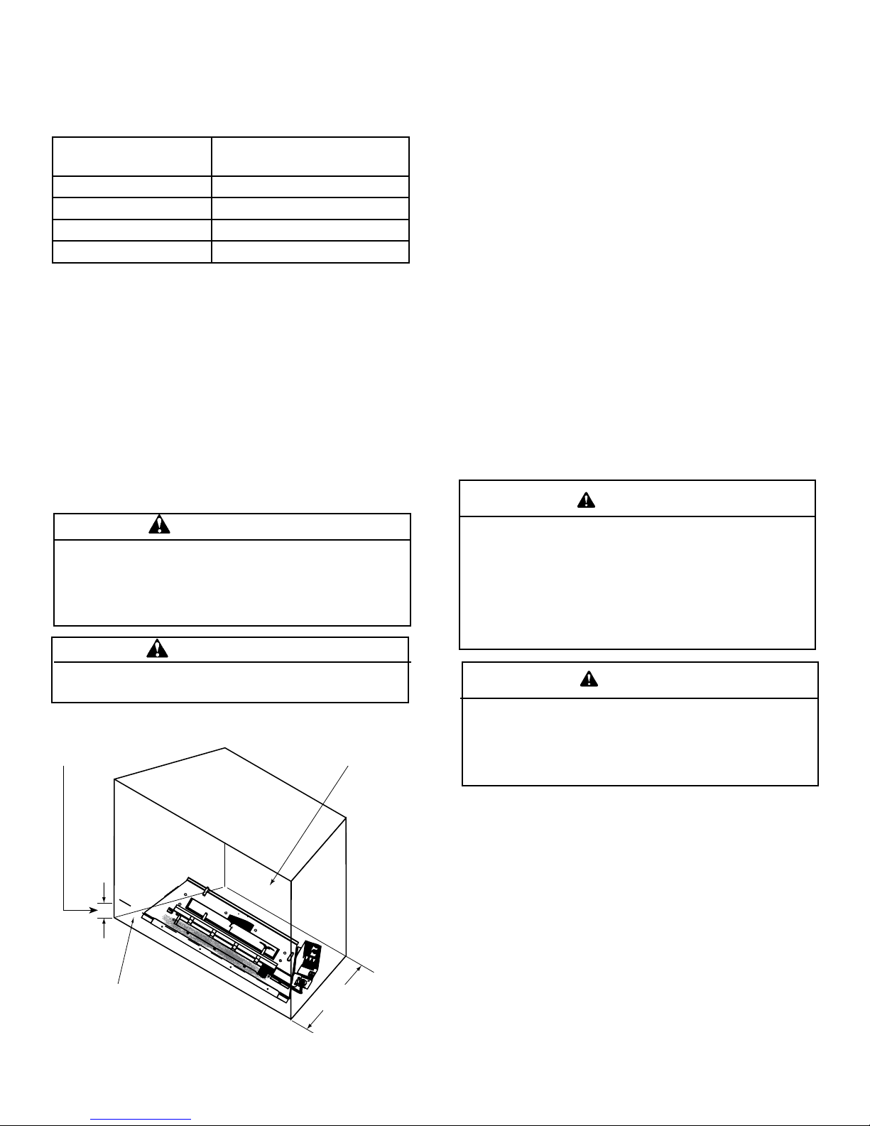
Depth of replace/rebox
(Refer to table)
The log set should be placed against
or as near as possible to the rear
wall of the replace/rebox.
Height of restrictive barrier caused by glass
door frames, recessed replaces, etc. from
the base or bottom surface of the unit.
(Refer to table)
Figure 2.2 - Reference Drawing of a Natural Flame Log Set in
an Enclosure with Glass Door or Barrier Installed
DO NOT INSTALL ANY GLASS OR BARRIERS ON A
VENTLESS FIREBOX
WARNING
F. Millivolt Ignition Controls
Natural Gas: An external regulator is required to reduce
supply pressure to a maximum of 10-1/2” w.c. on natural
gas systems operating at higher pressure.
The piezo ignitor allows ignition of the pilot without the use
of matches or batteries.
Milivoit control has four (4) positions:
OFF: All gas to the gas logs is shut off at the valve.
IGN: Valve position to light/maintain a standing pilot.
ON: Valve position to turn ON/OFF log set with remote
switch/thermostat.
LOW/HI: Variable position to control ame height (heat
output).
The gas log heater is tted with a specially designed safety
pilot (ODS assembly) which senses the amount of oxygen
available in the room and shuts the gas log heater off if the
oxygen level begins to drop below a satisfactory level. The
pilot can only be relit when adequate fresh air is available.
G. Pilot/ODS
Monessen • Glow Getter Owner’s /Installation Manual • 4606-900 Rev. A • 8/178
H. Adequate Combustion Ventilation Air
This heater shall not be installed in a conned space or
unusually tight construction unless provisions are provided
for adequate combustion and ventilation air.
The National Fuel Gas Code, (ANSI Z223.1/NFPA54),
denes a conned space as a space whose volume is less
than 50 cubic feet per 1,000 BTU per hour (4.8m
3
per kw)
of the aggregate input rating of all appliances installed in
that space, and an unconned space as a space whose
volume is not less than 50 cubic feet per 1,000 BTU per
hour (4.8 m3 per kw) of the aggregate input rating of all
appliances installed in that space. Rooms communicating
directly with the space in which the appliances are installed,
through openings not furnished with doors, are considered
a part of a conned space.
Unusually tight construction is dened as construction
where:
a. Walls and ceilings exposed to the outside atmosphere
have a continuous water vapor retarder with a rating of
1 perm (6 x 10
11
kg per pa/sec-m2) or less with openings
gasketed or sealed, and
b. Weather stripping has been added to windows and
doors, and
c. Caulking or sealants are applied to areas such as joints
around window and door frames, between sole plates
and oors, between wall-ceiling joints, between wall
panels, at penetrations for plumbing, electrical and gas
lines and other openings.
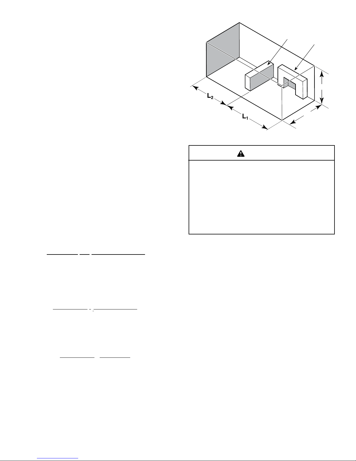
The following formula can be used to determine the maximum heater rating per the denition of unconned space:
BTU/Hr = (L1 + L2) Ft x (W) Ft x (H) Ft
50
Consider two connecting rooms with an open area
between, with the following dimensions:
L1 = 151/2 Ft., L2 = 12 Ft., W = 12 Ft., H = 8 Ft.
BTU/Hr = (151/2 + 12) x (12) x (8)
50
If there were a door between the two rooms the calculation
would be based only on the room with the heater.
BTU/Hr = (151/2) x (12) x (8)
50
W
H
Counter
Fireplace
Figure 2.3
If the area in which the heater may be
operated does not meet the required volume
for indoor combustion air, combustion and
ventilation air shall be provided by one
of the methods described in the National
Fuel Gas Code, ANSI Z223.1/NFPA 54, the
International Fuel Gas Code or applicable
local codes.
WARNING
9
Monessen • Glow Getter Owner’s /Installation Manual • 4606-900 Rev. A • 8/17
3
Clearances and Height Requirements
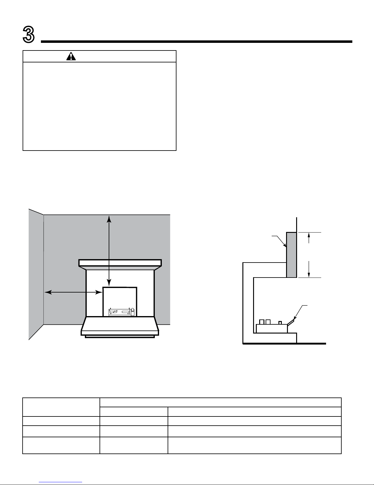
Sidewall and ceiling clearances: The sides of the re-
place opening must be at least 16" from any combustible
wall. The ceiling must be at least 42" from the top of the
replace opening.
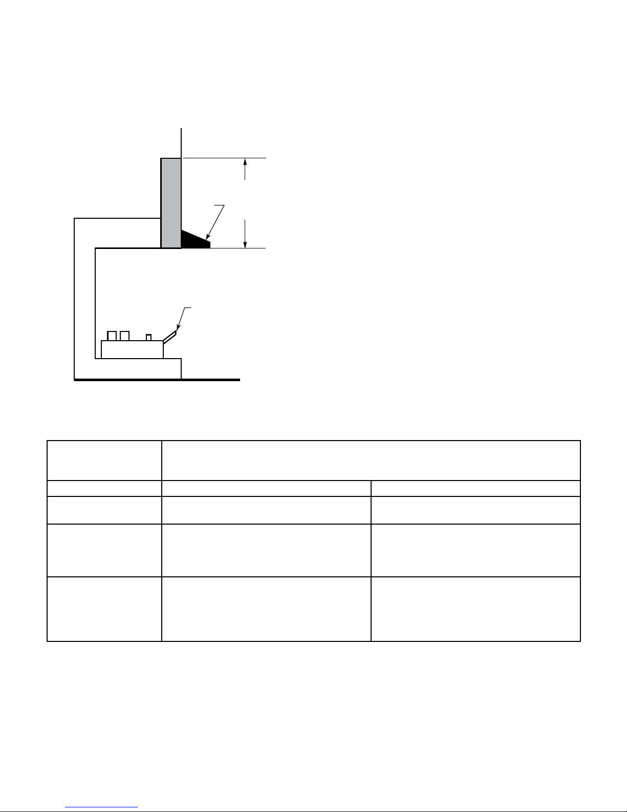
Heat resistant material (minimum requirements) with
no wooden mantel or other combustible projection:
To install the gas logs into a replace with no wooden
mantel, shelf or other combustible projection above the
replace opening, measure the heat resistant material
height, according to Figure 3.2 and TABLE A.
Heat resistant materials such as slate and marble must be
at least 1/2" thick. Sheet metal should not be installed
onto combustible material.
IMPORTANT: If you cannot meet these minimum clear-
ances you must operate the heater with chimney ue
damper open. Refer to “Installing Vented Applications”
found on page 13.
Heat resistant
Material
Measure
This
Distance
Heater in
Fireplace/
Firebox
Figure 3.2 - Measure Heat Resistant Material
Table A — Heat Resistant Material Requirements with No Mantel or Combustible Projection
Heat Resistant Material
Measurement
Requirements for Safe Installation
GG18 GG24
12" or more Hood not required Hood not required
8" or less than 12" Hood not required Extend heat resistant material to 12" or install hood. Figure 4
Less than 8" Extend heat resistant Extend heat resistant material to 8" AND install hood Figure 5.
OR Extend heat resistant material to a height of at least 12".
16"
42"
Figure 3.1 - Sidewall and Ceiling Clearances
The dimensions shown in Figures 3 through 11 and
dened in the replace manufacturer's instructions
are minimum clearances to maintain when installing
this heater. Left and right clearances are determined
when facing the front of the heater.
When heater is installed into a ventless rebox,
minimum clearances, as specied by the ventless
rebox manufacturer, must be met.
Follow these instructions carefully to ensure safe
installation. Failure to follow instructions exactly
can create a re hazard.
WARNING
Monessen • Glow Getter Owner’s /Installation Manual • 4606-900 Rev. A • 8/1710
Heat resistant material (minimum requirements) with
wooden mantel or other combustible projection:
To install the heater with a wooden mantel, shelf or other
combustible projection above, rst measure the heat resistant material shown in Figure 3.3, then refer to Table B.
Hood
Heater in Fireplace
or Firebox
8" or More
of Heat
Resistant
Material
Figure 3.3 - Measuring Heat Resistant Material for Mantel
Table B - Heat Resistant Material Requirements Height and Mantel Location
Heat Resistant
Material
Measurement
Requirements for Safe Installation with Wooden Mantel, Shelf or other Combustible
Projection
GG18 GG24
12" or more Hood not required. Observe proles (side
elevations) shown in Figure 3.4 .
Hood not required. Observe prole (side
elevations shown in Figure 3.6 .
8" or less than 12" Install hood and observe proles shown in
Figure OR Extend heat resistant material to
at least 12" and observe proles shown in
Figure
Install hood and observe proles shown
in Figure 3.5 . OR Extend heat resistant
material to at least 12" and observe proles
shown in Figure 3.6.
Less than 8" Extend heat resistant to at least 8", install
hood and observe proles shown in Figure
3.5 . OR Extend heat resistant material to
at least 12" and observe proles shown in
Figure 3.4 .
Extend heat resistant material to least 8",
install install hood and observe proles
shown in Figure 3.5 . OR Extend heat
resistant material to at least 12" and
observe proles shown in Figure 3.4 .
11
Monessen • Glow Getter Owner’s /Installation Manual • 4606-900 Rev. A • 8/17
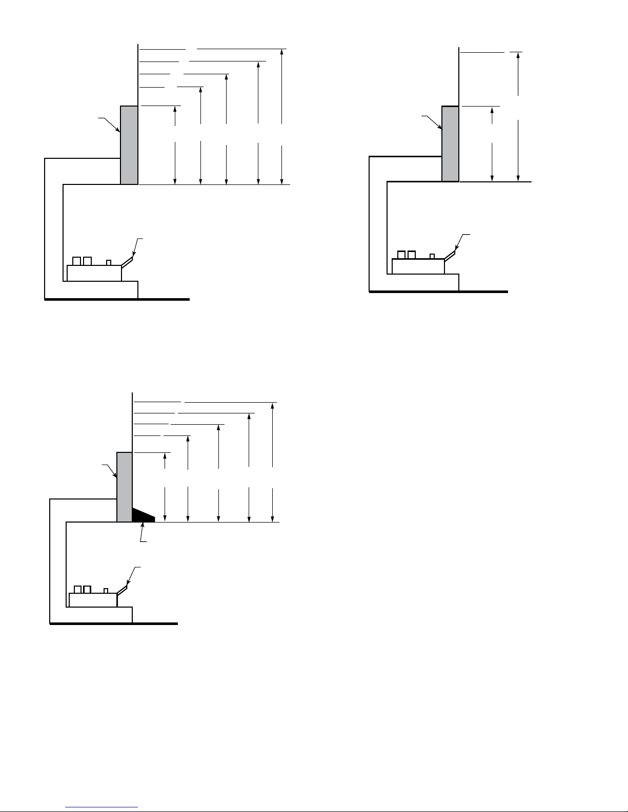
Figure 3.5 - Minimum Mantel Clearance with Hood — All
Models
Example: A mantel may project from the wall a maximum
of 21⁄2" at a minimum of 8" above the opening, and a
maximum of 6" at a minimum of 141⁄2" above the opening.
10"
8"
6"
2¹⁄₂"
8" 14" 20¹⁄₂" 24⁵⁄₈" 28"
Example: A mantel may project from the wall a maximum
of 21⁄2" at a minimum of 14" above the opening, and a
maximum of 6" at a minimum of 201⁄2" above the opening.
Figure 3.4 - Minimum Mantel Clearance with No Hood —
GG18
Heat
Resistant
Material
Heater in
Fireplace or
Firebox
10"
8"
6"
2¹⁄₂"
8" 14¹⁄₂" 18⁵⁄₈" 22¹⁄₂" 26"
12"
Heat
Resistant
Material
Heater in
Fireplace or
Firebox
Hood
Figure 3.6 -Minimum Mantel Clearance with No Hood —
GG18/24
Example: The bottom of the mantel may project from the
wall a maximum of 10" at a minimum of 28" above the
opening.
10" or less
12" min.
28"
Heat
Resistant
Material
Heater in
Fireplace or
Firebox
Monessen • Glow Getter Owner’s /Installation Manual • 4606-900 Rev. A • 8/1712
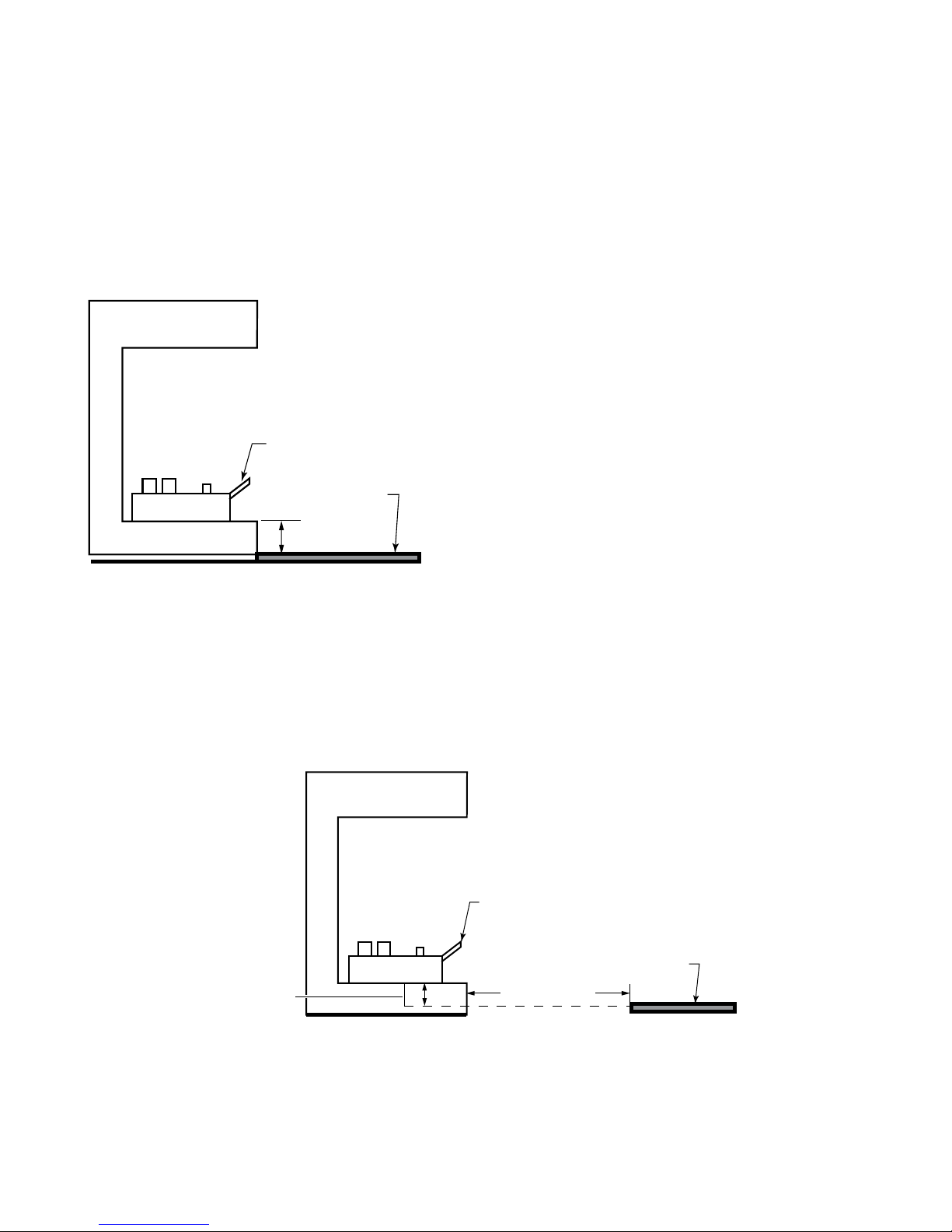
The gas log heater must be installed at least 13⁄8" above
any combustible ooring material, such as carpeting or
tile, which is closer than 14" to the base of the replace.
The minimum distance must be maintained from the top
surface of carpeting, tile, etc. Figure 3.7
OR
The gas log heater may be installed nearer to the oor if a
minimum of 14" of noncombustible material such as slate
or marble is installed between the base of the replace and
the combustible ooring. Figure 3.8
Figure 3.7 - Minimum Clearance above Combustible
Flooring
Heater in Fireplace
or Firebox
Combustible
Material
1
3
⁄8" Minimum
Figure 3.8 - Minimum Clearance above Combustible
Flooring with Noncombustible Material Installed at Base
of Fireplace
14” Minimum
Heater in Fireplace
or Firebox
Combustible
Material
This Distance
May Now be
Less Than 1
3
⁄8"
13
Monessen • Glow Getter Owner’s /Installation Manual • 4606-900 Rev. A • 8/17
Before Fully Installing the Unit:
•
Turn OFF the gas supply to the replace or rebox.
• Seal any fresh air vents and/or ash clean-out doors
located on the oor or wall of the replace. If left
unsealed, drafting may cause pilot outage or soot-
ing. Use a heat resistant sealant. Do not seal the
chimney ue damper.
Vented Application Installations -
Millivolt controlled gas logs may be installed as a vented
decorative log set in compliance with ANSI Z21.60 and
National Fuel Gas Code, Section 6.6. (Since, the gas logs
are operated with the damper open, non-combustible
material and minimum mantel requirements do not
apply.)
Before installing the appliance:
• Turn off gas supply to replace or rebox.
• Have the replace oor and chimney professionally
cleaned to remove ashes, soot, creosote or other
obstructions. Have this cleaning performed annually
after installation.
• Seal any fresh air vents or ash clean-out doors
located on oor or wall of replace. If not, drafting
may cause pilot outage or sooting. Use a heatresistant sealant.
Install and operate the appliance as directed in this
manual.
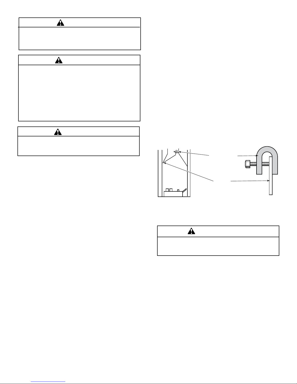
Damper stop installation:
A damper stop must be provided with the unit. Contact your
dealer to obtain one. The damper stop must be installed as
shown in Figure 3.9 to prevent full closure of the replace
damper blade and provide a minimum 29 square inch ue
opening.
Figure 3.9 - Damper Stop Installation.
Damper Stop
Damper
Before installing in a solid fuel burning replace,
The chimney ue and rebox must be cleaned of
soot, creosote, ashes and loose paint by a qualied
chimney cleaner.
WARNING
This log set can be installed in a solid fuel burning
fireplace (masonry fireplace or manufactured
replace) with a working ue and constructed of
non combustible material or in a vent-free rebox.
Exception: DO NOT install this appliance in a factory-
built replace that includes instructions stating that
it has not been tested or should not be used with
unvented gas logs. This log set may be installed as
a vented log set.
WARNING
The use of thermostat is not allowed in vent-less
application except with a thermostat remote with 2
hours shutoff.
WARNING
When this log set is installed in a vented application,
the damper must be clamped to be fully open.
WARNING
Monessen • Glow Getter Owner’s /Installation Manual • 4606-900 Rev. A • 8/1714
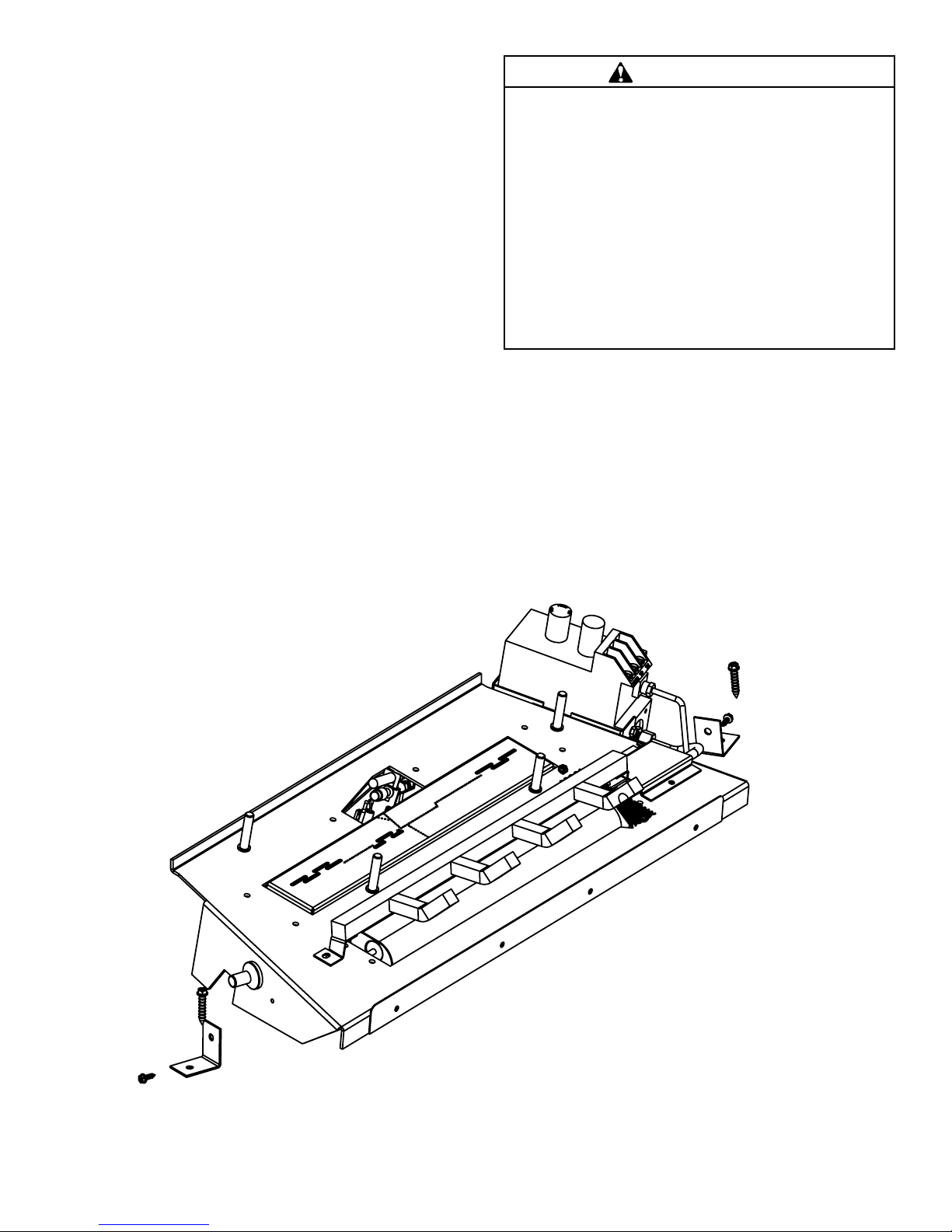
Figure 3.10 - Securing Heater to Floor of Fireplace/Fireox
Assembly Procedure
1. Attach the two brackets shipped with the engine
assembly to the engine base on the right and left hand
side using the two sheet metal screws shipped with the
brackets.
2. Center the burner assembly inside the fireplace or
firebox. Make certain that the front of the burner
assembly sits inside the front edge of the replace or
the rebox.
3. Anchor holes are located on the right and left sides of the
brackets attached to the engine base. After centering
the burner assembly correctly, mark the holes on the
replace or rebox oor. Drill two (2) 5/32” diameter holes
approximately 1 ¼” deep. Anchor the two anchoring
screws shipped with the unit using ¼” hex head chuck
and secure the burner assembly to the replace through
the holes drilled earlier.
You must secure the gas log heater to the replace
oor. If not, the entire unit may move when you
adjust the controls. Movement of unit may cause
shifting of the gas logs which leads to sooting and
improper burning. Grate movement could cause a
gas leak.
Special care is required if you are installing the unit
into a sunken replace. You must raise the replace
oor to allow access to gas log controls. This will
insure adequate air ow and guard against sooting.
Raise the fireplace floor using noncombustible
materials, as described in Placement in a Fireplace
with Restrictive Barrier on Page 7.
WARNING
15
Monessen • Glow Getter Owner’s /Installation Manual • 4606-900 Rev. A • 8/17
4
Gas Information
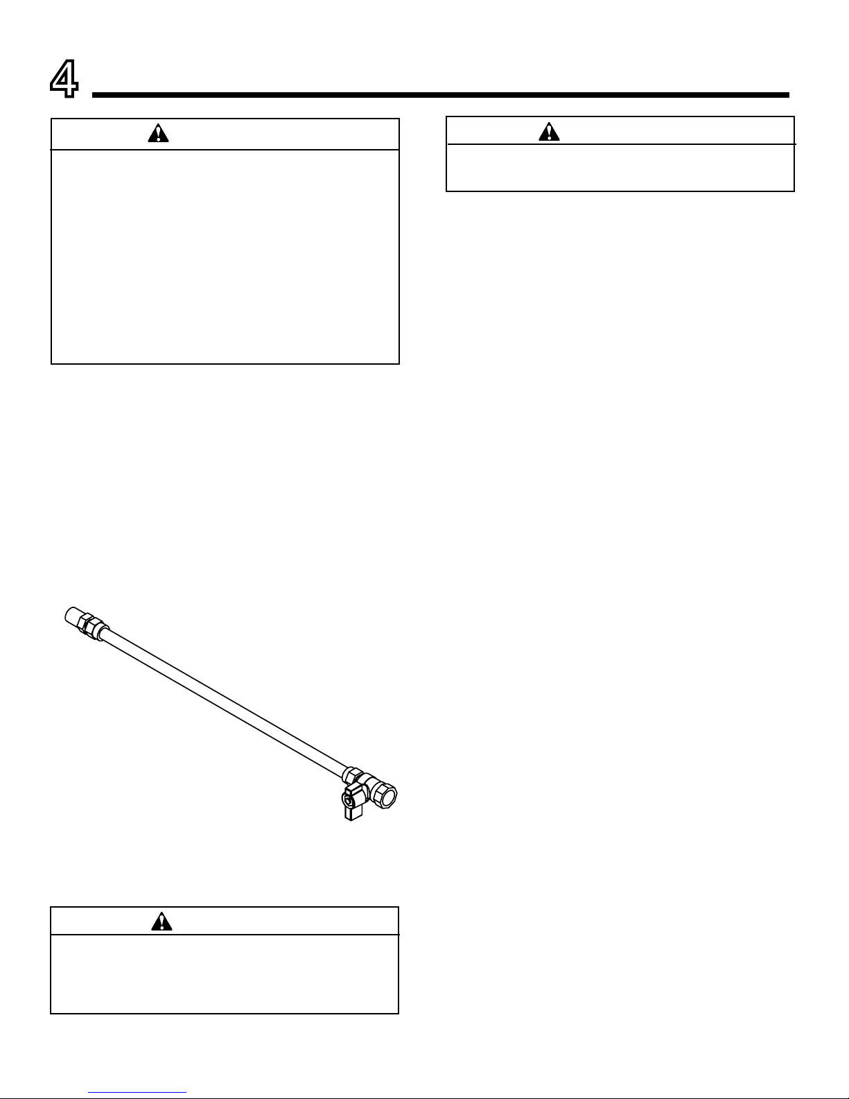
A. Gas Line Connection
NOTICE: A qualied gas appliance installer must connect
the heater to the gas supply. Consult all local codes.
IMPORTANT: Hold heater valve rmly with a wrench to
prevent movement when connecting to inlet pipe.
Always use an external regulator for all propane/LPG
heaters and high pressure one to two-pound systems
only, to reduce the supply tank pressure to a maximum of
13" w.c. This is in addition to the internal regulator in the
heater valve.
The heater gas inlet connection is a 3/8" NPT at the valve.
On all control type units, the inlet connection is on the right
side of unit. To connect from the opposite side, route the
pipe around the back portion of the unit.
When tightening up the joint to the valve, hold the valve
securely to prevent movement.
Test all gas joints from the gas meter to the heater valve for
leaks using a gas analyzer or soap and water solution after
completing connection. DO NOT USE AN OPEN FLAME.
Check the gas pressure with the appliance burning and
the control set to HIGH.
B. Millivolt Valve Control
The valve regulator controls the burner pressure which
should be checked at the pressure test point.
Turn captured screw counter clockwise two or three turns
and then place tubing to pressure gauge over test point
(Use test point “OUT” closest to control knob). After taking
pressure reading, be sure and turn captured screw clock-
wise rmly to re-seal. Do not over torque. Check for gas
leaks.
Use new black iron or steel pipe. Internally tinned
copper or copper tubing can be used per National
Fuel Code, section 2.6.3, providing gas meets
hydrogen sulde limits, and where permitted by local
codes. Gas piping system must be sized to provide
minimum inlet pressure (Listed on Data Plate) at the
maximum ow rate (BTU/hr). Undue pressure loss
will occur if the pipe is too small.
A manual shutoff valve must be installed upstream
of the appliance. Union tee and plugged 1/8" NPT
pressure tapping point should be installed upstream
of the appliance.
WARNING
Connecting directly to an unregulated propane/
LPG tank can cause an explosion.
WARNING
CHECK GAS TYPE: The gas supply must be the
same as stated on the heater’s rating plate. If the
gas supply is different, DO NOT INSTALL THE
HEATER. Contact your dealer for the correct model.
WARNING
Figure 4.1 Gas Connection
 Loading...