

Page 1
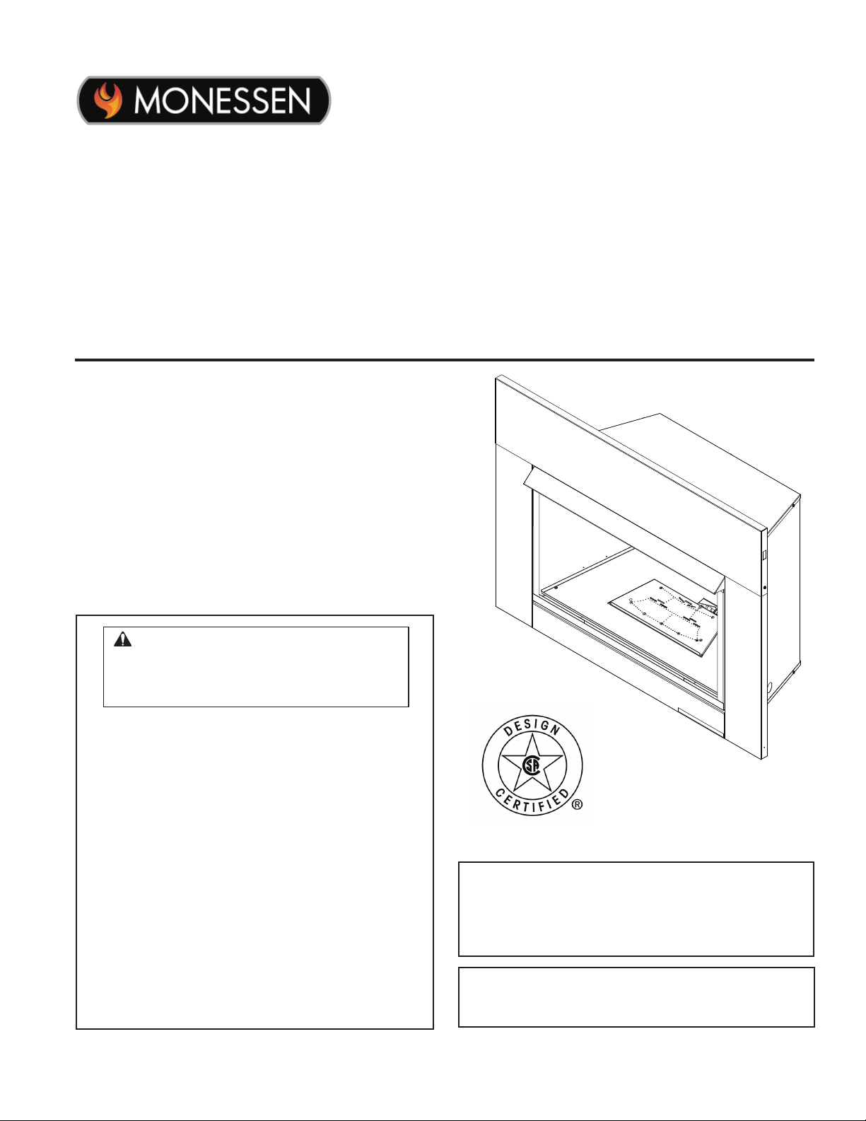
VFI Series Vent Free Gas Fireplace
Installation & Operating Instructions
Models: VFI33L(N/P)(V/I), VFI33C(N/P)(V/I)
WARNING: If the information in this
manual is not followed exactly, a re or
explosion may result causing property
damage, personal injury or loss of life.
• Do not store or use gasoline or other
ammable vapors and liquids in the
vicinity of this or any other appliance.
• WHAT TO DO IF YOU SMELL GAS
– Do not try to light any appliance.
– Do not touch any electrical switch; do
not use any phone in your building.
– Leave the building immediately.
– Immediately call your gas supplier from
a neighbor's phone. Follow the gas
supplier's instructions.
– If you cannot reach your gas supplier,
call the re department.
• Installation and service must be performed
by a qualied installer, service agency or
the gas supplier.
This is an unvented gas-red heater. It uses air
(oxygen) from the room in which it is installed.
Provisions for adequate combustion and ventilation air must be provided. Refer to Page 7.
INSTALLER: Leave this manual with the appliance.
CONSUMER: Retain this manual for future
reference.
Monessen • VFI33 Owner Manual • 20307670 • Rev H • 1/2020
Page 2

CONTENTS
VFI33 Vent Free Gas Fireplace System
Thank you and congratulations on your purchase of a Monessen vent free gas replace.
PLEASE READ THE INSTALLATION AND OPERATION INSTRUCTIONS
BEFORE USING THE APPLIANCE.
IMPORTANT: Read all instructions and warnings carefully before starting installation.
Failure to follow these instructions may result in a possible re hazard and will void the warranty.
Important Safety Information ...................................... 3
Codes ....................................................................... 4
Product Features .......................................................... 5
Operation ................................................................. 5
Gas Pressures ......................................................... 5
Gas Specications And Orice Size .........................5
Ignition Controls .......................................................5
Pilot ..........................................................................5
Thermal Generator ................................................... 5
Fireplace And Framing Dimensions ...........................6
Fireplace And Framing Dimensions ......................... 6
Pre-Installation Information ......................................... 7
Framing Dimensions ................................................7
Getting Started ......................................................... 7
What You Will Need For Installation .........................7
Clearances And Height Requirements .......................8
Before Installing The Fireplace Insert ...................... 9
Heat Resistant Material ............................................ 9
Installation ................................................................... 10
Remove Screen ..................................................... 10
Install Canopy ........................................................ 10
Secure Heater To Floor .......................................... 11
Connect Gas Line ....................................................... 12
Connecting The Gas Line ...................................... 12
Gas Pressure – Millivolt .............................................. 13
Checking Gas Pressure – Millivolt Control ............. 13
Electrical Wiring – Millivolt ......................................... 14
Connect Optional Wall Switch Or Thermostat ........14
Connect Remote Receiver ..................................... 15
Check System Operation ....................................... 15
Operating Instructions – Millivolt ..............................16
For Your Safety Read Before Lighting ................... 16
What To Do If You Smell Gas .................................16
Lighting Pilot For The First Time ............................ 16
Lighting Pilot ..........................................................17
Lighting Burner ....................................................... 18
To Turn Off Gas ......................................................18
Check Gas Pressure – IPI ...................................... 19
Electrical Installation – IPI .......................................... 19
Electrical Wiring ..................................................... 19
Junction Box Wiring ............................................... 19
IPI System Wiring Diagram ....................................20
Operating Instruction – IPI .........................................21
For Your Safety Read Before Lighting ................... 21
What To Do If You Smell Gas .................................21
Operating Instructions ............................................ 21
To Turn Off Gas To The Appliance .........................21
Operating And Indications ...................................... 22
Electrical Wiring – Fan ................................................ 23
Log Placement ............................................................ 24
Before You Begin ...................................................24
Rock Wool Placement ............................................ 25
Install Berkley Oak Logs ........................................ 25
Install Highland Oak Logs ...................................... 27
Install Kentucky Wildwood Logs ............................28
Install Beachcomber and Riverwood Logs.............30
Fireglass Placement ..............................................31
Flame Appearance ................................................. 32
Visual Flame Check ............................................... 32
Check The Pilot Flame ........................................... 32
Thermostat And Millivolt Control ............................ 32
Operating Instructions ............................................ 32
Operating Instructions ............................................... 31
For Your Safety Read Before Lighting ................... 33
What To Do If You Smell Gas .................................33
Millivolt/Thermostat Control Lighting Instructions .. 34
To Turn Off Gas To Heater ..................................... 34
Match Lighting Instructions .................................... 34
Blower Operation ................................................... 34
Cleaning And Servicing .............................................36
Annual Cleaning And Inspection ............................ 36
Periodic Cleaning ................................................... 36
Troubleshooting .........................................................37
Replacement Parts ..................................................... 39
Firebox Assembly ...................................................39
Millivolt Burner Assembly ....................................... 40
IPI Burner Assembly .............................................. 41
Berkley Oak Logs ................................................... 42
Beachcomber and Riverwood Logs........................43
Highland Oak Logs ................................................44
Kentucky Wildwood Logs ....................................... 45
►
Warranty ...................................................................... 46
2
Monessen • VFI33 Owner Manual • 20307670 • Rev H • 1/2020
Page 3
VFI33 Vent Free Gas Fireplace System
IMPORTANT SAFETY INFORMATION
INSTALLER
Please leave these instructions with the appliance.
OWNER
Please retain these instructions for future reference
.
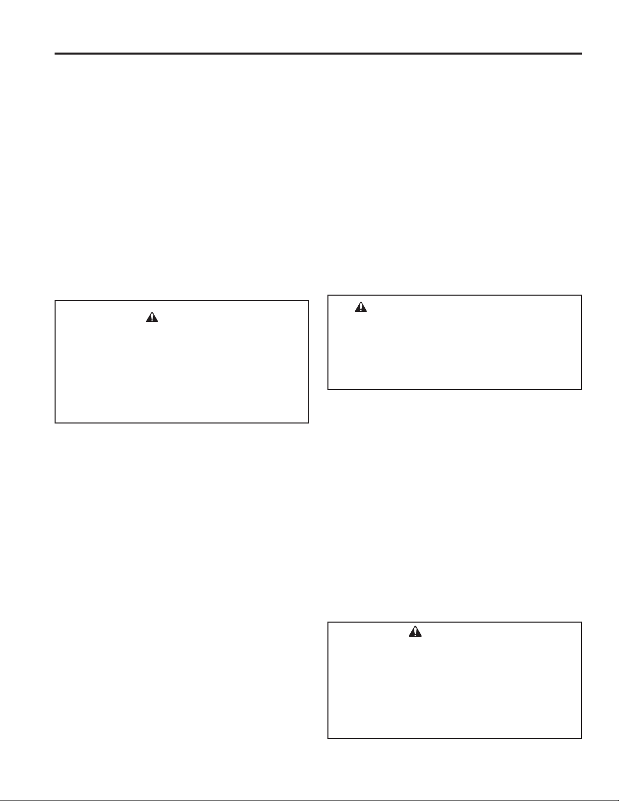
WARNING!
• Any change to this heater or its controls can be dangerous.
• Improper installation or use of the heater can cause serious injury or death from re, burns,
explosion or carbon monoxide poisoning.
• Do not allow fans to blow directly into the replace. Avoid any drafts that alter burner ame
patterns.
• Do not use a blower insert, heat exchanger insert or other accessory, not approved for use with
this heater where applicable.
WARNING!
1. Due to high temperatures, the appliance should be
located out of trafc and away from furniture and
draperies.
2. Children and adults should be alerted to the hazard
of high surface temperature and should stay away
to avoid burns or clothing ignition.
3. Young children should be carefully supervised when
they are in the same room with the appliance.
4. Do not place clothing or other ammable material
on or near the appliance.
5. Any safety screen or guard removed for servicing
an appliance, must be replaced prior to operating
the heater.
6. Installation and repair should be done by a qualied
service person.
7. To prevent malfunction and/or sooting, an unvented
gas heater should be cleaned before use and at
least annually by a professional service person.
More frequent cleaning may be required due to
excessive lint from carpeting, bedding materials,
etc. It is imperative that control compartments,
burners and circulating air passageways be kept
clean.
8. CARBON MONOXIDE POISONING: Early signs of
carbon monoxide poisoning are similar to the u with
headaches, dizziness and/or nausea. If you have these
signs, obtain fresh air immediately. Have the heater
serviced as it may not be operating properly.
9. The installation must conform with local codes or, in
the absence of local codes, with the National Fuel
Gas Code, ANSI Z223.l/NFPA54.
10. This unit complies with the latest edition of ANSI
Z21.11.2, Unvented Heaters.
11. Do not install the heaters in a bathroom or bedroom.
12. Correct installation of the ceramic ber logs, proper
location of the heater, and annual cleaning are necessary to avoid potential problems with sooting. Sooting,
resulting from improper installation or operation, can
settle on surfaces outside the replace. See log place-
ment instructions for proper installation.
13. Avoid any drafts that alter burner ame patterns. Do not
allow fans to blow directly into replace. Do not place
a blower inside burn area of rebox. Ceiling fans may
create drafts that alter burner ame patterns. Sooting
and improper burning will occur.
14. CAUTION: Candles, incense, oil lamps, etc. produce
combustion byproducts including soot. Vent-free
appliances will not lter or clean soot produced by
these types of products. In addition, the smoke and/or
aromatics (scents) may be re-burned in the vent-free
appliance which can produce odors. It is recommended
to minimize the use of candles, incense, etc. while the
vent-free appliance is in operation.
15. This is an unvented gas-fired heater. It uses air
(oxygen) from the room in which it is installed. Provisions for adequate combustion and ventilation air must
be provided.
16. This heater shall not be installed in a room or space
unless the required volume of indoor combustion air is
provided by the method described in the National Fuel
Gas Code, ANSI Z223.1/NFPA 54, the International
Fuel Gas Code or applicable local codes.
17. Keep room area clear and free from combustible materials, gasoline and other ammable vapors and liquids.
18. Unvented gas heaters are a supplemental zone heater.
They are not intended to be the primary heating appliance.
19. Unvented gas heaters emit moisture into the living
area. In most homes of average construction, this
does not pose a problem. In houses of extremely
tight construction, additional mechanical ventilation is
recommended.
Monessen • VFI33 Owner Manual • 20307670 • Rev H • 1/2020
3
Page 4
IMPORTANT SAFETY INFORMATION
VFI33 Vent Free Gas Fireplace System
20. During manufacturing, fabricating and shipping, various
components of this appliance are treated with certain
oils, lms or bonding agents. These chemicals are not
harmful but may produce annoying smoke and smells
as they are burned off during the initial operation of the
appliance; possibly causing headaches or eye or lung
irritation. This is a normal and temporary occurrence.
The initial break-in operation should last four hours
with the burner at the highest setting. Provide maximum ventilation by opening windows or doors to allow
odors to dissipate. Any odors remaining after this initial
break-in period will be slight and will disappear with
continued use.
21. Input ratings are shown in BTU per hour and are for
elevations up to 2,000 feet. For elevations above 2,000
feet, input ratings should be reduced 4 percent for each
1,000 feet above sea level. Refer to the National Fuel
Gas Code.
22. The appliance must be isolated from the gas supply
piping system by closing its equipment shutoff valve
during any pressure testing of the gas supply piping
system at test pressures equal to or less than 1/2 psig
(3.5 kPa).
23. Do not use this room heater if any part has been under
water. Immediately call a qualied service technician
to inspect the room heater and to replace any part of
the control system and any gas control which has been
under water.
24. Never burn solid fuels in a replace where a unvented
room heater is installed.
25. Always have a replace screen in place when the
appliance is in operation and, unless other provisions
for combustion air are provided, the screen must have
an opening(s) for induction of combustion air.
THIS APPLIANCE MAY BE INSTALLED IN AN
AFTER-MARKET, PERMANENTLY LOCATED,
MANUFACTURED (MOBILE) HOME, WHERE
NOT PROHIBITED BY LOCAL CODES.
THIS APPLIANCE IS ONLY FOR USE WITH THE
TYPE OF GAS INDICATED ON THE RATING
PLATE. THIS APPLIANCE IS NOT CONVERTIBLE FOR USE WITH OTHER GASES.
WARNING: Never connect unit to private
(non-utility) gas wells. This gas is commonly
known as wellhead gas.
WARNING: This product and the
fuels used to operate this product (liquid
propane or natural gas), and the products
of combustion of such fuels, can expose
you to chemicals including benzene, which
is known to the State of California to cause
cancer and reproductive harm. For more
information go to: www.P65Warnings.
ca.gov.
CODES
Adhere to all local codes or, in their absence, the latest edition of THE NATIONAL FUEL GAS CODE ANSI Z223.1 or
NFPA54 which can be obtained from…
American National Standards Institute, Inc.
1430 Broadway
New York, NY 10018
or
National Fire Protection Association, Inc.
Batterymarch Park
Quincy, MA 02269
4
Monessen • VFI33 Owner Manual • 20307670 • Rev H • 1/2020
Page 5
VFI33 Vent Free Gas Fireplace System
PRODUCT FEATURES
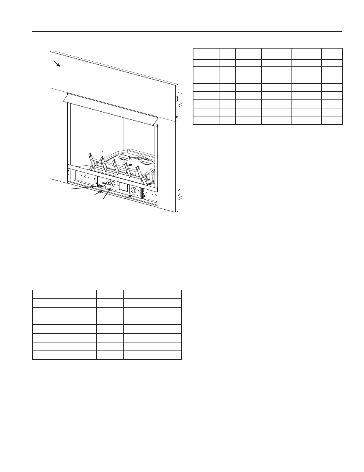
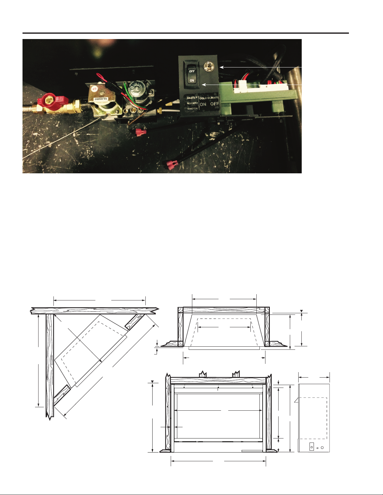
VFI33 CONTROLS
Surround
On/Off Switch
Piezo Ignitor
Control Knobs
Figure 1. Unvented Gas Heater with Control Access Door Open
Blower
OPERATION
This unvented gas heater requires no outside venting and
burns cleanly with high heating efciency.
GAS PRESSURES
Control Fuel Millivolt T-stat
Regulator Pressure Natural 3.5" w.c.
Pilot Regulator Natural 3.5" w.c.
Max. Inlet Pressure Natural 10.5" w.c.
Min. Inlet Pressure Natural 5.0" w.c.
Regulator Pressure LP 10.0" w.c.
Max. Inlet Pressure LP 13.0" w.c.
Min. Inlet Pressure LP 11.0" w.c.
GAS SPECIFICATIONS AND ORIFICE SIZE
MODEL FUEL CONTROL
VFI33LNV NAT. Millivolt 28,000 19,000 #38
VFI33LPV LP. Millivolt 27,000 22,000 #52
VFI33CNV NAT. Millivolt 28,000 19,000 #38
VFI33CPV L P. Millivolt 27,000 22,000 #52
VFI33LNI NAT. IPI 28,000 19,000 #38
VFI33LPI L P. IPI 27,000 22,000 #52
VFI33CNI NAT. IPI 28,000 19,000 #38
VFI33CPI LP. IPI 27,000 22,000 #52
MAX. INPUT
(BTU/h)
NOTE: For LP models an external regulator is required
to reduce supply pressure to a maximum of 13" w.c.
MIN. INPUT
(BTU/h)
ORIFICE
SIZE
IGNITION CONTROLS
Piezo ignitor allows ignition of the pilot without the use of
matches or batteries.
Millivolt and EcoLogic® 2.0 controls have four (4)
positions:
OFF - All gas to the gas logs is shut off at the
valve.
IGN - Valve position to light/maintain a standing
pilot.
ON - Valve position to turn ON/OFF log set with
remote switch/thermostat.
LOW/HI - Variable position to control ame height
(heat output). Both front and rear burners
are in operation to provide realistic glow
and yellow ame.
PILOT
The gas log heater is tted with a specially designed safety
pilot light (ODS assembly) which senses the amount of
oxygen available in the room and shuts the gas log heater
off if the oxygen level begins to drop below a satisfactory
level. The pilot can only be re-lit when adequate fresh air
is available.
THERMAL GENERATOR
The millivolt gas log pilot is tted with a millivolt generator
to provide power for remote activation.
COLD CLIMATE OPTION (IPI MODELS ONLY)
NOTE: If you live in a cold climate, seal all cracks around
your appliance and wherever cold air could enter the room,
with noncombustible material. It is especially important to
insulate the outside chase cavity between the studs and
under the oor on which the appliance rests, if the oor is
above ground level.
Your replace is equipped with an intermittent pilot ignition
(IPI) control. An IPI control with a standing pilot option
provides the dual benet of an economical and environmentally responsible product and one which lights easily
even in the coldest climates. When in intermittent pilot
Monessen • VFI33 Owner Manual • 20307670 • Rev H • 1/2020
5
Page 6
FIREPLACE AND FRAMING DIMENSIONS
Figure 2. Cold Climate Option
VFI33 Vent Free Gas Fireplace System
Cold Climate
Switch
Master Switch
mode (as it comes from the factory), your pilot remains
unlit until needed, saving you fuel. Standing pilot mode,
by comparison, is characterized by a continuously burning
pilot. The benet of a pilot which lights only when needed
is fuel savings. However, with no pilot burning in your replace, units operating in colder climates may experience
delayed start up or lock out. Because colder air is heavier
than milder air and there is no pilot burning to maintain
a warm stable temperature in your rebox, establishing
a draft to aid ignition becomes difcult. This is perfectly
normal but can be somewhat frustrating.
FIREPLACE AND FRAMING DIMENSIONS
1
37
⁄4"
"
8
7
⁄
31
⁄4"
1
37
"
4
1
⁄
64
1/2"
or 5/8"
Rough
Opening
Height
To remedy this issue, your replace has been designed with
a cold climate pilot option, which, when active, maintains
a warmer temperature inside your rebox to make ignition
faster and more efcient. Operating your appliance in cold
climate (aka standing) pilot mode will prohibit the need for
multiple ignition attempts and will prevent the system from
delaying start up or locking out.
To activate the cold climate option, simply move the cold
climate toggle switch located on the right side of the black
control center to the “On” (left) position. (Figure 2.) You can
operate your appliance in this mode regardless of whether
you are using a remote control, wall switch or thermostat.
225⁄8 "
215⁄8 "
331⁄2" Rough Opening Width
13⁄8 "
Rough
Opening
Depth
16"
181⁄4 "
161⁄2 "
Figure 3. Fireplace and Framing Dimensions
6
Monessen • VFI33 Owner Manual • 20307670 • Rev H • 1/2020
24
333⁄8 "
31"
19"
237⁄8 "
31⁄2 "
1
⁄2"
11⁄8 "
Page 7
VFI33 Vent Free Gas Fireplace System
PRE-INSTALLATION INFORMATION
FRAMING DIMENSIONS
If unit is to be “built in,” replace framing can be built before
or after the appliance is set in place. BE SURE THAT ALL
PACKING MATERIAL HAS BEEN REMOVED FROM THE
UNDERSIDE OF THE UNIT PRIOR TO SETTING THE
FIREBOX IN PLACE. Construct replace framing following
Figure 3 on page 6. The framing headers may not rest
directly on top of the rebox.
The replace may be installed directly on a combustible
oor or a raised platform of an appropriate height. Do
not place replace on carpeting, vinyl, tile or other soft
oor coverings. It may, however, be placed on at wood,
plywood, particle board or other hard surfaces. Be sure
replace rests on a solid continuous oor or platform with
appropriate framing for support and so that no cold air can
enter from under the rebox. Your vent-free replace must
be mounted to the oor or the replace hearth.
WARNING!
• Handle the gas log burner assembly by the
grate only. Do not pick the unit up by the
burners.
• Gloves are recommended when handling
ceramic ber logs to prevent skin irritation
from loose bers. Logs are fragile — handle
with care.
GETTING STARTED
Make sure you have received all parts
Check your packing list to verify that all listed parts have
been received. You should have the following:
• Installation/Operating instructions
• 33" unvented gas heater
• Canopy
• Volcanic rock and rock wool (traditional sets only)
• Stone and reglass kit (contemporary sets only)
• Two (2) anchoring screws
• Mounting screws for canopy
Accessories required to nish the installation:
One of two surrounds:
• VFICFSS Black small surround 32"H x 43"W
• VFICFSL Black large surround 35"H x 50"W
One of three rebox liners:
• FBVFIC(M/LR) Firebrick
• BLPVFIC Black porcelain panels
• BMGVFIC Black Magic glass panels
The millivolt controlled version of this heater is the only
style designed to be operated with optional devices for
ON/OFF functions. The following options may be used
with the millivolt controlled heater. These options are not
packaged with the unit.
• Hand held Remote with Receiver
• Wall switch with 15' wire.
• Hand held Thermostat Remote with Receiver
IPI controlled versions of this unit have the following options
that may be used but are not packaged with the unit.
• IPIFKN2: Stepper motor kit (NG)
• IPIFKP2: Stepper motor kit (LP)
Carefully inspect the contents for shipping damage. If any
parts are missing or damaged, immediately inform the
dealer from whom you purchased the appliance. Do not
attempt to install any part of the appliance unless you have
all parts in good condition.
WARNING! Do not install the heater:
• Where curtains, furniture, clothing, or
other ammable objects are less than
42" from the front of the heater.
• In high trafc areas.
• In windy or drafty areas.
WHAT YOU WILL NEED FOR INSTALLATION
You must have the following items available before proceeding with installation:
• External regulator (for propane / L.P.G. and 1/2 lb.
Natural Gas systems only)
• Piping which complies with local codes
• Sediment trap
• Tee joint
• Pipe wrench or appropriate size crescent wrench set
• Phillips head screwdriver
• Drill with 5/32" bit
• Surround
• Manual shutoff valve
• Pipe sealant approved for use with liquid propane
(resistant to sulfur compounds)
WARNING!
If the area in which the heater is operated
does not meet the required volume for indoor
combustion air, combustion and ventilation
air shall be provided by one of the methods
described in the National Fuel Gas Code, ANSI
Z223.1/NFPA 54, the International Fuel Gas
Code or applicable local codes.
Monessen • VFI33 Owner Manual • 20307670 • Rev H • 1/2020
7
Page 8
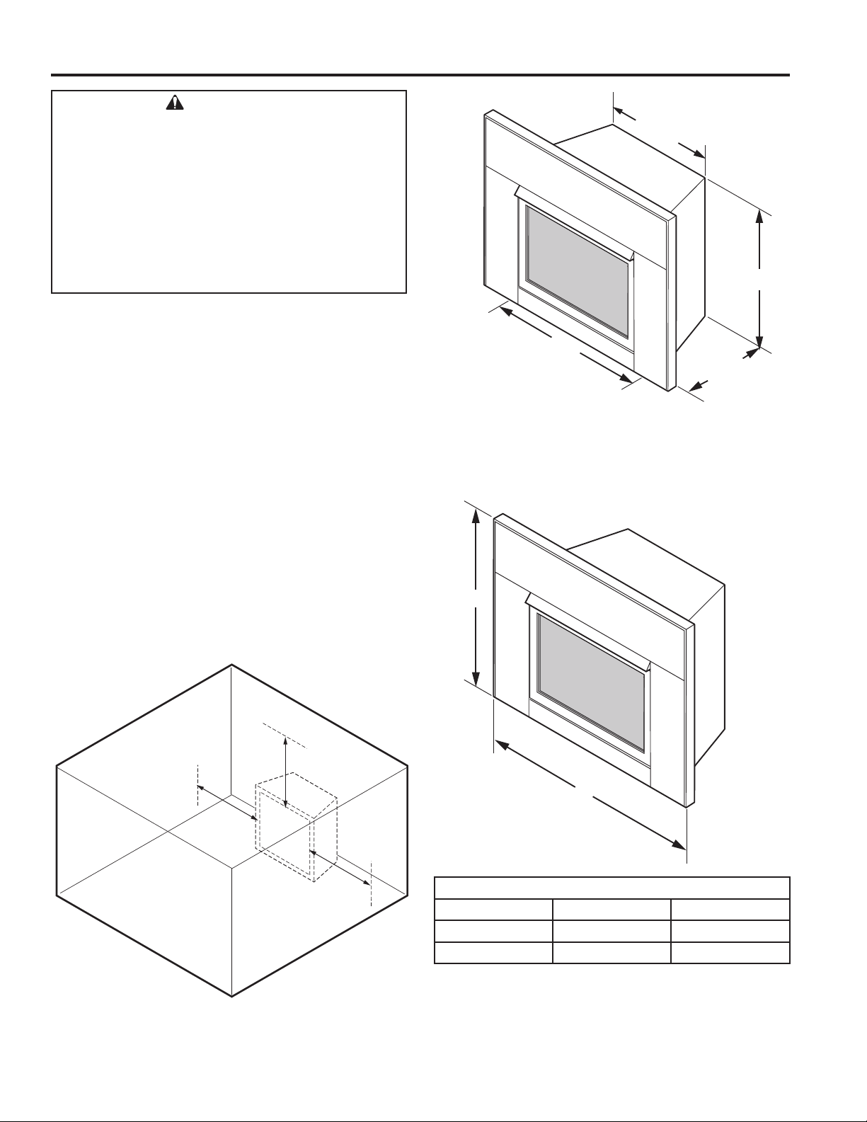
CLEARANCE AND HEIGHT REQUIREMENTS
B
A
WARNING!
The dimensions shown in Figures 4 and 5
and dened in the replace manufacturer's
instructions are minimum clearances to
maintain when installing this heater. Left and
right clearances are determined when facing
the front of the heater.
Follow these instructions carefully to ensure
safe installation. Failure to follow instructions
exactly can create a re hazard.
NOTE: Clearances are necessary to combustible surfaces
only. No clearance is necessary for noncombustible surface.
Sidewall clearances: The clearance from the inside of the
appliance to any combustible adjacent wall should no be
less than 9". Figure 4.
Ceiling clearance: The ceiling must be at least 42" from
the top of the rebox opening. Figure 4.
Back wall clearance: The appliance can be placed against
the combustible back wall.
Floor clearance: The replace may not be installed onto
any combustible ooring material, such as carpeting, vinyl
or tile without the hearth or a minimum 22 GA (0.030") metal
or a minimum 1/2" wooden base covering the entire width
and depth of the base.
Mantel clearances: The canopy supplied with the unit
must be installed. If a combustible mantel is installed. It
must meet the clearance requirements shown in Figure 8.
VFI33 Vent Free Gas Fireplace System
22
3/4
23 7/8
33"
15 1/4
Figure 5. Dimensions for Installing in Masonry Fireplace or UL Listed
Box
9"
Minimum
Figure 4. Sidewall and Ceiling Minimum Clearances
8
42"
Minimum
9"
Minimum
Surround Dimensions*
A B
FP2770
Small 32" 43"
Large 35" 50"
*A surround is required to complete the installation.
Figure 6. dimensions
Monessen • VFI33 Owner Manual • 20307670 • Rev H • 1/2020
Page 9
VFI33 Vent Free Gas Fireplace System
BEFORE INSTALLING THE FIREPLACE
INSERT
Have replace oor and chimney professionally cleaned to
remove ashes, soot, creosote or other obstructions. Close
and seal any fresh air vents or ash clean-out doors located
on oor or wall
HEAT RESISTANT MATERIAL
(MINIMUM REQUIREMENTS) WITH NO
WOODEN MANTEL OR OTHER COMBUSTIBLE
PROJECTION
Heat resistant material (minimum requirements) with
wooden mantel or other combustible projection:
To install the heater with a wooden mantel shelf or other
combustible projection above, rst measure the heat resistant material shown in Figure 7.
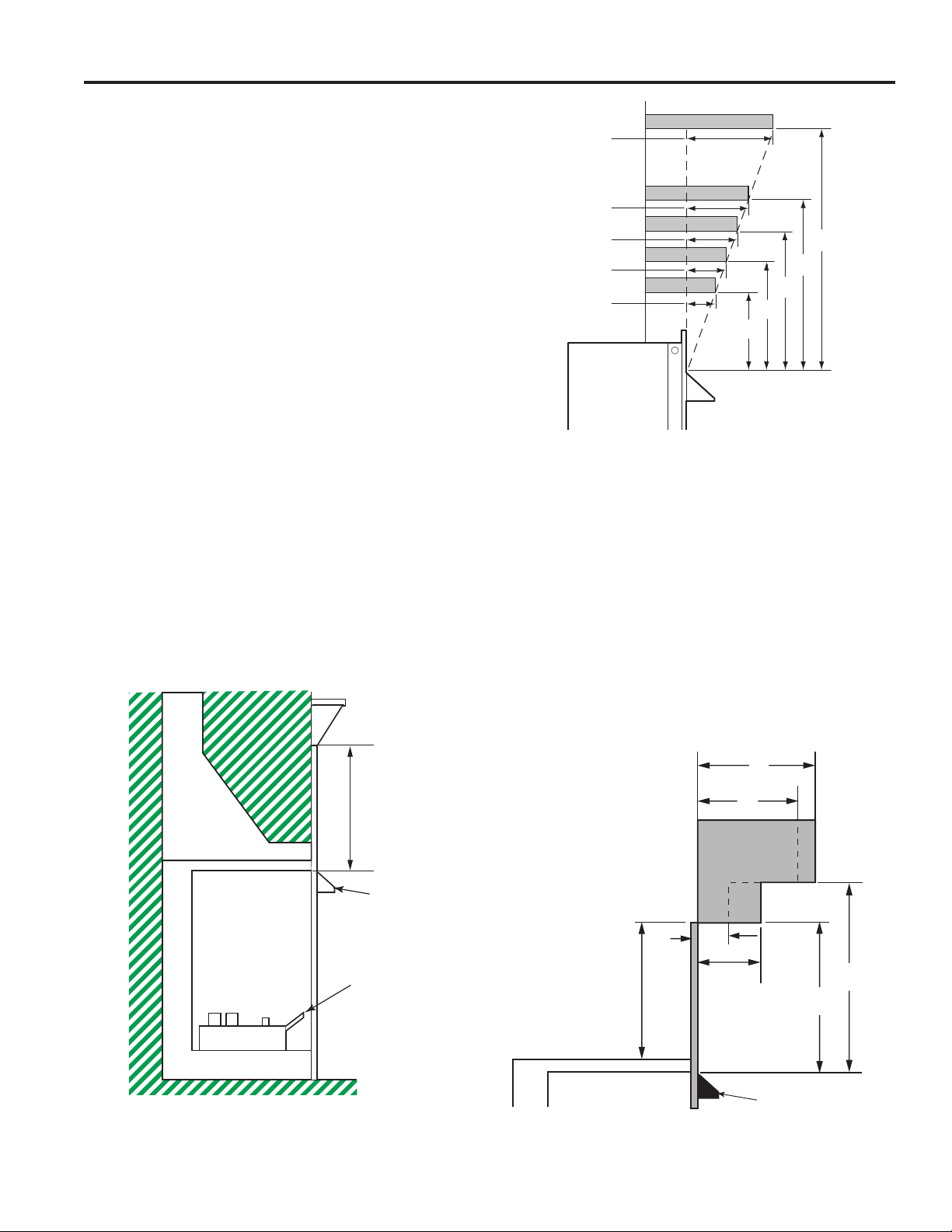
CLEARANCE AND HEIGHT REQUIREMENTS
12"
10"
8"
6"
2¹⁄₂”
10"
8"
Figure 8. Minimum Mantel Clearances
Example: A mantel may project from the wall a maximum of
21⁄2" at minimum of 8" above the opening, and a maximum
of 12" at a minimum of 26" above the opening.
26"
14"
12"
No combustible
materials within 8"
of opening.
Hood
Grate
Figure 9. is an example of an unsafe mantel installation.
The mantel projects 4" at 8" above the opening, exceeding the maximum acceptable distance of 21⁄2". The mantel
also projects 8" at 10" above the opening, exceeding the
maximum acceptable distance of 6".
If your mantel prole is unsafe, you may either:
• Raise the mantel to an acceptable height or,
• Remove the mantel.
8"
6"
1
2
No combustible
materials within 8"
of opening.
/2"
4"
10"
8"
Figure 7. Measure Heat Resistant Material for
Mantel
Monessen • VFI33 Owner Manual • 20307670 • Rev H • 1/2020
Hood
Figure 9.
9
Page 10
INSTALLATION
VFI33 Vent Free Gas Fireplace System
The gas log heater must be installed at least 5" above
any combustible ooring material, such as carpeting or
tile, which is closer than 14" to the base of the replace.
Figure 10.
Combustible
5"
Noncombustible
Material
Figure 10. Minimum Clearance above Combustible Flooring
1”
Material
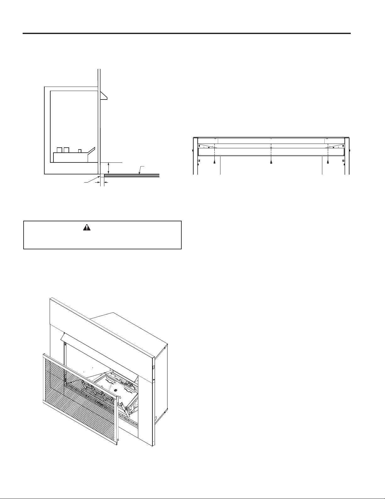
INSTALL CANOPY
1. Remove the replace screen as described in the previous section.
2. Align canopy with the holes in the top frame assembly.
Figure 12.
3. Install the three (3) screws (in owner’s manual packaging) which attach the canopy to the top frame assembly.
Figure 12.
4. Tighten all screws. Make sure the canopy is level and
secure. Install the replace screen.
Figure 12. Install Canopy
WARNING!
Do not operate the unit without the screen frame
panel and canopy installed.
REMOVE SCREEN
Remove replace screen by pushing screen frame panel
up and out. Figure 11.
NOTE: Fireplace screen must be removed to access log
box and to install canopy.
Figure 11. Remove Fireplace
Screen
10
Monessen • VFI33 Owner Manual • 20307670 • Rev H • 1/2020
Page 11
VFI33 Vent Free Gas Fireplace System
INSTALLATION
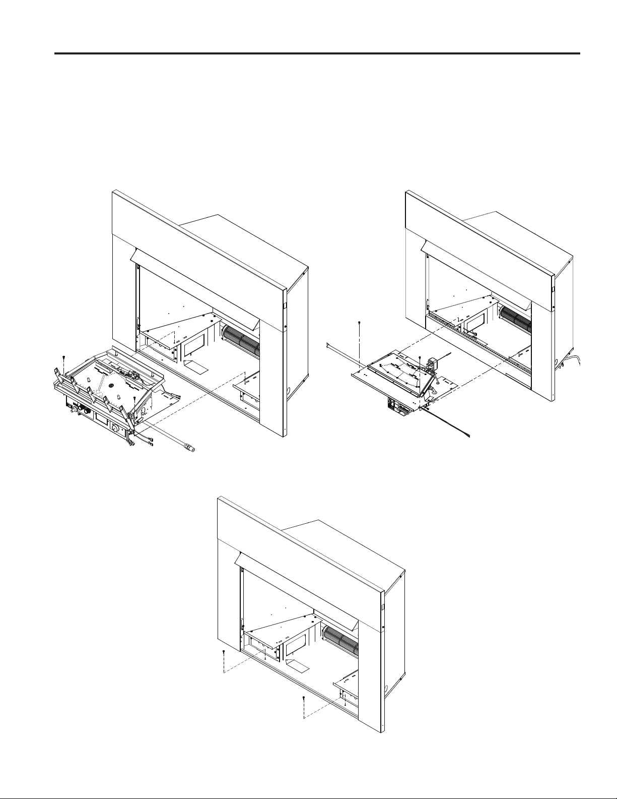
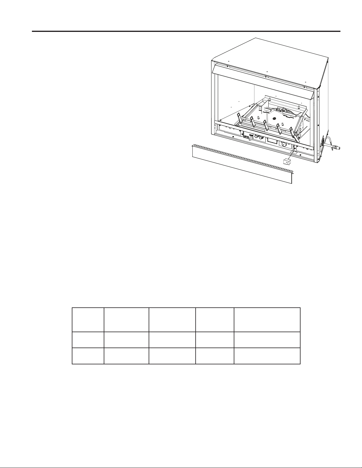
SECURE HEATER TO FLOOR
NOTE: Clearance requirements as detailed in “Clearances
and Height Requirements” section of this manual must be
met before securing heater in place.
To prevent movement, the heater must be secured to the
oor or hearth.
1. To remove the grate and base assembly, take out two
screws as shown in Figure 13. and Figure 14.
2. Lift grate and base assembly out of the rebox.
3
3. Secure the rebox with two anchoring screws (
⁄16" x 11⁄2"
length) supplied with the replace system. Figure 15.
NOTE: If the unit is mounted on carpeting, tile or combustible material without the hearth, a metal or wooden
base covering the entire width and depth of the base
must be installed.
Figure 13. Remove Grate and Base Assembly (VFI33L models)
Figure 15. Secure Firebox to Floor or Hearth
Monessen • VFI33 Owner Manual • 20307670 • Rev H • 1/2020
Figure 14. Remove Base Assembly (VFI33C models)
11
Page 12
CONNECT GAS LINE
VFI33 Vent Free Gas Fireplace System
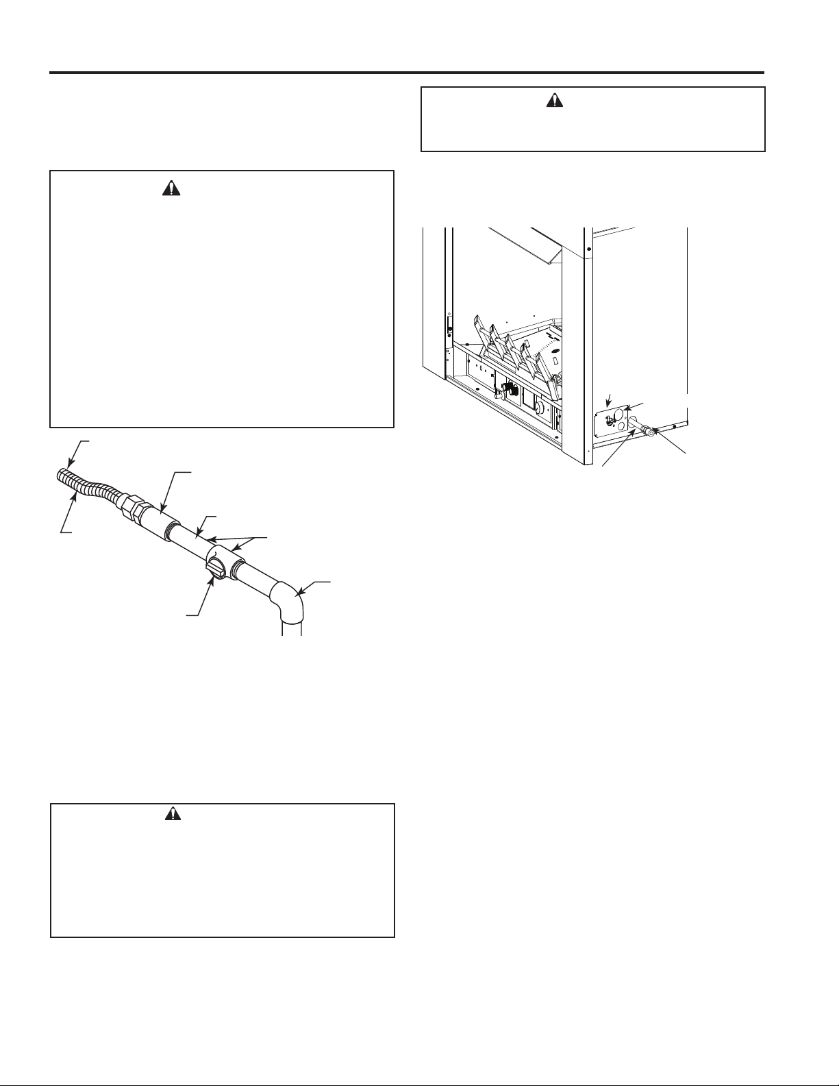
CONNECTING THE GAS LINE
NOTICE: A qualied gas appliance installer must connect
the heater to the gas supply. Consult all local codes.
WARNING!
Use new black iron or steel pipe. Internally tinned
copper or copper tubing can be used per National
Fuel Code, section 2.6.3, providing gas meets
hydrogen sulde limits, and where permitted by
local codes. Gas piping system must be sized to
provide minimum inlet pressure (Listed on Data
Plate) at the maximum ow rate (BTU/hr). Undue
pressure loss will occur if the pipe is too small.
A manual shutoff valve must be installed
upstream of the appliance. Union tee and
plugged 1/8" NPT pressure tapping point should
be installed upstream of the appliance. Figure 16.
To Fireplace
Pipe Coupling
Pipe
Stainless
Flexible Tube
Manual Shutoff
Valve
Figure 16. Gas
Connection
IMPORTANT: Loosen the pipe adapter on the ex tube
before installing to the system piping.
Always use an external regulator for all propane/LPG heaters only, to reduce the supply tank pressure to a maximum
of 13" w.c. This is in addition to the internal regulator in the
heater valve.
Locations Pressure
Tapping Point
Installation
Gas Supply
Inlet
WARNING!
Connecting directly to an unregulated propane/
LPG tank can cause an explosion
To reach factory installed ex line, go through access door
on right or left side of rebox.
Access Door
for Gas Line
Stainless Flex Line
Figure 17. Access Holes
The stainless ex line is on the right side facing the replace and can connect to either a 3/8 NPT female or 1/2
NPT male pipe. To connect from the opposite side, route
the pipe under the rear portion of the unit.
Test all gas joints from the gas meter to the heater valve for
leaks using a gas analyzer or soap and water solution after
completing connection. DO NOT USE AN OPEN FLAME.
Check the gas pressure with the appliance burning and
the control set to HIGH.
Open control access door on either side of unit to nd valve
and regulator referred to below. Figure 17.
Cord Protector
Manual Gas Shutoff
(Recommended Outlet
Positioned Vertical)
WARNING!
CHECK GAS TYPE: The gas supply must be the
same as stated on the heater’s rating plate. If the
gas supply is different, DO NOT INSTALL THE
HEATER. Contact your dealer for the correct
model. Connecting to the wrong gas type may
result in property damage or personal injury.
12
Monessen • VFI33 Owner Manual • 20307670 • Rev H • 1/2020
Page 13
VFI33 Vent Free Gas Fireplace System
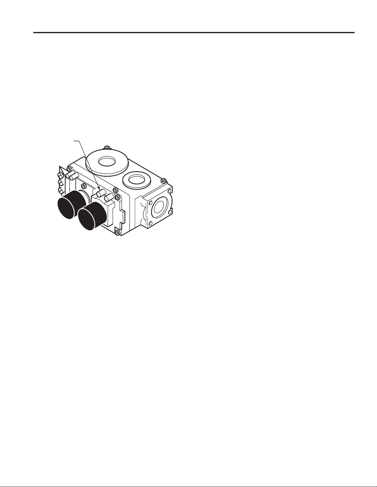
CHECKING GAS PRESSURE: – MILLIVOLT
CONTROL
Figure 18.
The valve regulator controls the burner pressure which
should be checked at the pressure test point.
Turn captured screw counter clockwise two or three turns
and then place tubing to pressure gauge over test point
(Use test point “OUT” closest to control knob). After taking
pressure reading, be sure and turn captured screw clockwise rmly to re-seal. Do not over torque. Check for gas
leaks.
Test Port
"OUT"
GAS PRESSURE — MILLIVOLT
Figure 18. Pressure Test Point Location Millivolt Control
FP2781
Monessen • VFI33 Owner Manual • 20307670 • Rev H • 1/2020
13
Page 14
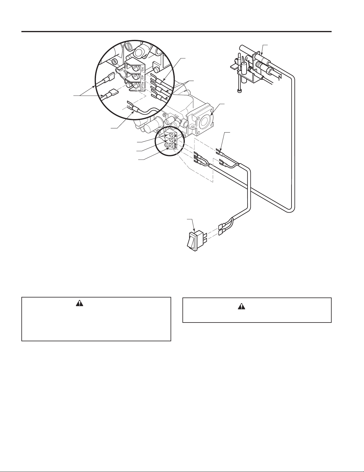
ELECTRICAL WIRING — MILLIVOLT
VFI33 Vent Free Gas Fireplace System
ODS Pilot
On/Off
Switch
Field Installed Optional
Wall Switch or
Remote Receiver
On/Off
Switch
ODS
Pilot
Valve
Spade
Terminal
TH = 3
TP = 1
TP/TH = 2
Switch
Figure 19. Wiring Diagram
WARNING!
Label all wires prior to disconnection when
servicing controls.
Wiring errors can cause improper and dangerous
operation. Verify proper operation after servicing.
The millivolt valve is a self-powered combination gas control THAT DOES NOT REQUIRE 110V AC TO OPERATE.
Refer to Figure 19. and installation instructions provided
with optional wall switch, thermostat or remote control for
wiring instructions. A maximum length of 15 feet of 18awg
two conductor wire is to be used for wall switch or thermostat installations.
NOTE: Thermostats and switches must be suitable for
millivolt operation.
WARNING!
Do NOT connect wall switch to 110 V circuit.
CONNECT OPTIONAL WALL SWITCH OR
THERMOSTAT
1. Use 18 awg, two-wire cable, 15 feet maximum length.
2. At one end of the cable, connect both wires to the wall
switch or thermostat. At the other end, connect one
wire to TP/TH and one wire to TH, or connect the wall
switch/thermostat to the two male (0.25") terminals on
the left side of the unit. The color of the wires does not
matter.
14
Monessen • VFI33 Owner Manual • 20307670 • Rev H • 1/2020
Page 15
VFI33 Vent Free Gas Fireplace System
CONNECT REMOTE RECEIVER
THESE INSTRUCTIONS SUPERCEDE THE SECTION
ENTITLED “HEARTH MOUNT” IN THE MILLIVOLT
HAND-HELD REMOTE INSTRUCTIONS SUPPLIED
WITH THE REMOTE.
Figure 20.
1. Remove bottom control door.
2. Connect the remote connector wires located in the unit
to the remote receiver.
®
3. Stick Velcro
of remote receiver and to oor of compartment behind
access panel.
4. Attach remote receiver to rebox with Velcro
Control switch must face forward.
NOTE: Do not place remote in combustion chamber,
only the remote receiver.
CHECK SYSTEM OPERATION
The millivolt system and individual components may be
checked with a millivolt meter having a 0-1000 mV range.
Conduct each check shown in chart below by connection
meter test leads to terminals as indicated.
pads with self-adhesive backing to bottom
®
pads.
ELECTRICAL WIRING — MILLIVOLT
Remote
Receiver
Figure 20. Install Remote Receiver
A. COMPLETE MILLIVOLT SYSTEM CHECK
(“A” Reading: Thermostat contacts CLOSED,
control knob “ON,” main burner should turn ON)
a. If the reading is more than 100 millivolts and the
automatic valve still does not come on, replace the
control.
b. If the closed circuit reading (“A” reading) is less than
100 millivolts, determine cause for low reading, proceed to Section B below.
Connect Meter
Check
Test
A
B
To
Test
Complete
System
Thermopile
Output
Leads to
Terminals
B. Thermopile Output Reading Check
(“B” Reading: Thermostat contacts OPEN, main
burner OFF)
1. Check gas pressure to the unit. If gas pressure is
within minimum and maximum on data plate, then
check pilot voltage, 325 millivolts minimum. If the
minimum millivolt reading is not obtainable, replace
pilot.
Switch or
Thermostat
Contacts
Meter Reading
Should Be
2 & 3 Closed Closed
1 & 2 Open Open
Monessen • VFI33 Owner Manual • 20307670 • Rev H • 1/2020
15
Page 16

OPERATING INSTRUCTIONS – MILLIVOLT
VFI33 Vent Free Gas Fireplace System
FOR YOUR SAFETY READ BEFORE LIGHTING
WARNING!
If you do not follow these instruction exactly, a re or explosion may result causing property
damage, personal injury or loss of life.
A. This appliance is equipped with a pilot which must be lit with built-in piezo ignitor while following these
instructions exactly.
B. BEFORE OPERATING smell all around the appliance area for gas. Be sure to smell next to the oor
because some gas is heavier than air and will settle on the oor.
WHAT TO DO IF YOU SMELL GAS:
• Turn off all gas to the appliance.
• Open windows.
• Do not attempt to light any appliance.
• Do not touch any electric switch; do not use any phone in your building.
• Immediately call your gas supplier from a neighbor's phone. Follow the gas supplier's instructions.
• If you cannot reach your gas supplier, call the re department.
C. Use only your hand to push in, or turn the gas control knob. Never use tools. If the knob will not push
in or turn by hand, don't try to repair it. Call a qualied service technician. Force or attempted repair
may result in a re or explosion.
D. Do not use this appliance if any part of it has been under water. Immediately call a qualied service
technician to inspect the appliance and to replace any part of the control system and any gas control
that has been under water.
LIGHTING PILOT FOR THE FIRST TIME
INITIAL LIGHTING
Purge air from the supply line as follows:
• Open main shutoff valve.
• Unscrew main pressure test point.
• Leave inlet test screw open until gas comes in.
• When gas is owing, tighten inlet screw immediately.
NEVER use open ame to check for gas leaks.
LEAK TESTING
1. Follow the pipe from the gas supply line connection to the gas valve. Check connection for leaks
with soap and water mixture.
2. Next check for gas leaks at the burner with soap and water mixture.
3. Check the pilot for gas leaks with soap and water mixture.
16
Monessen • VFI33 Owner Manual • 20307670 • Rev H • 1/2020
WARNING!
Page 17

VFI33 Vent Free Gas Fireplace System
PILOT
OPERATING INSTRUCTIONS — MILLIVOLT
LIGHTING PILOT FOR THE FIRST TIME
APPROVED LEAK TESTING METHOD
You may check for gas leaks with the following methods only:
• Soap and water solution
• An approved leak testing spray
• Electronic sniffer
NOTE: Remove any excessive pipe compound from the connections. Excessive pipe compound
can set off electronic sniffers.
WARNING!
NEVER use open ame to check for gas leaks.
If using a soap and water solution to test for leaks,
WARNING!
DO NOT spray solution onto control body.
Check for gas leaks in each of the following locations:
• Pipe from the gas supply line connection to the gas valve
• Burner connections • Field made joints / gas shutoff valve
• Pilot • Factory made joints
• Each joint or connection • All joints on valve and control body
LIGHTING PILOT
WARNING!
The control has an interlock device that does not allow the lighting of the replace up to the
moment the safety device of the ame has not interrupted the gas ow. After that period of time
(when the magnet is closed), it is possible to start the lighting operation.
The gas control knob is designed to be operated by hand. DO NOT use any tools during this
operation. Damaged knobs may result in serious injury.
1. Depress and turn knob counterclockwise
to pilot position.
2. Depress fully and hold pilot gas knob. Depress piezo igniter as many times as needed to ignite pilot.
Keep knob fully depressed for a few seconds. Release and check that pilot continues to burn.
If the pilot does not stay lit, repeat steps 1 and 2.
O
N
T
O
L
I
P
F
F
O
Pilot Position
Continued on next page
Monessen • VFI33 Owner Manual • 20307670 • Rev H • 1/2020
17
Page 18

PILOT
PILOT
OPERATING INSTRUCTIONS – MILLIVOLT
LIGHTING BURNER
LIGHTING THE BURNER
Depress and turn the knob counterclockwise to the “ON” position.
It will take less than four (4) seconds for the burner to ignite.
MAIN BURNER SWITCH
This switch allows you to turn on and to turn off the main burner
without using the gas valve knob. is in the “ON” position to light the
main burner.
O
N
T
O
L
I
P
F
F
O
VFI33 Vent Free Gas Fireplace System
Wall Switch
N
O
O
F
F
P
I
L
T
O
Pilot Position
Depress and turn knob clockwise
Off Position
On Position
TO TURN OFF GAS
to “OFF” position.
I
L
P
O
T
F
F
O
O
N
PILOT
18
Monessen • VFI33 Owner Manual • 20307670 • Rev H • 1/2020
Page 19

VFI33 Vent Free Gas Fireplace System
ELECTRICAL INSTALLATION — IPI
CHECK GAS PRESSURE – IPI
1. Check gas type. The gas supply must be the same as
stated on the appliance’s rating decal. If the gas supply
is different from the replace, STOP! Do not install the
appliance. Contact your dealer immediately.
2. To facilitate easier installation, a 18" (610 mm) ex line
with manual shut-off valve has been provided with this
appliance. Install and attach 1/2" gas line onto shut-off
valve.
3. After completing gas line connection, purge air from
gas line and test all gas joints from the gas meter to the
replace for leaks. Use a solution of 50/50 water and
soap solution or a gas sniffer.
4. To check gas pressures at valve, turn captured screw
counter clockwise 2 or 3 turns and then place tubing
to pressure gauge over test point. Turn unit to high.
Figure 21. After taking pressure reading, be sure and
turn captured screw clockwise rmly to reseal. Do not
over torque. Check test points for gas leaks.
WARNING!
DO NOT use open ame to check for gas leaks.
Pressure Inlet
WARNING!
Electrical connections should only be
performed by a qualied, licensed electrician.
Main power must be off when connecting to
main electrical power supply or performing
service. All wiring shall be in compliance with
all local, city and state codes. The appliance,
when installed, must be electrically grounded
in accordance with local codes or in the
absence of local codes, with the National
Electrical Code ANSI/NFPA 70 (latest edition)
and Canadian Electrical Code, CSA C22.1.
ELECTRICAL WIRING
General
This replace is equipped with an IPI control valve which
operates on 6 volts. The 6 volt DC adapter plugs into the
replace junction box A/C power supply.
It is equipped with a battery back-up which will operate
the unit for approximately 48 hours in the event of a power
failure using on/off function only. Use of high/low function
will reduce battery life while in back-up mode.
Optional Accessories
This replace may be used with a wall switch, wall mounted
thermostat or IPI hand held remote control.
FP3034
Pilot Adjust-
Pressure
Outlet
Figure 21. IPI Valve
ment Screw
CAUTION!
Label all wires before disconnecting when
servicing controls. Wiring errors can cause
improper and dangerous operation.
WARNING!
DO NOT connect to a 110V circuit.
JUNCTION BOX WIRING
1. This should be done before framing the replace. Wire
the receptacle into an electrical circuit. Wire with minimum 60° C wire in accordance with prevailing codes.
2. Remove the external junction box cover by removing
the screw from the side of the outside rebox wall.
Junction box was installed at the factory.
3. The junction box cover has a factory installed “romex”
style strain relief connector. After connecting the wires,
route the wire leads through this connector. Refer to
the wiring diagram in Figure 22.
120V AC
60Hz
Factory Supplied
Not Supplied
Junction Box
Figure 22. Junction Box Wiring Diagram
Monessen • VFI33 Owner Manual • 20307670 • Rev H • 1/2020
19
Page 20

ELECTRICAL INSTALLATION – IPI
VFI33 Vent Free Gas Fireplace System
WALL SWITCH INSTALLATION
The wall switch wire connection is located off the wire
harness coming out of the IPI Control Board. The label is
wired 'wall switch'. Connect the low voltage switch wires to
the two (2) terminals labeled "wall switch" from the control
IPI SYSTEM WIRING DIAGRAM
ORANGE
YELLOW
BLACK
board. Run wire to desired location on wall. Up to 50 feet
of 18 gauge wire may be used if necessary. Attach wires
to wall switch. Mount the wall switch in a junction box and
screw on cover. Figure 23.
BLACK
RED
RED
RED
BLACK
RED
BROWN
RED
GROUND
RED
BLACK
GREEN
D/C POWER
BLACK
Figure 23. IPI System Wiring Diagram
CAUTION!
Electrical connections should only be performed by a qualied, licensed electrician. Main
power supply must be turned off before connecting fans to the main electrical power supply
or performing service.
20
Monessen • VFI33 Owner Manual • 20307670 • Rev H • 1/2020
Page 21

VFI33 Vent Free Gas Fireplace System
OPERATING INSTRUCTIONS – IPI
FOR YOUR SAFETY READ BEFORE LIGHTING
WARNING!
If you do not follow these instructions exactly, a re or explosion may result causing property
damage, personal injury or loss of lie.
A. This appliance is equipped with an ignition device which automatically lights the pilot. Refer to the
instructions.
B. BEFORE OPERATING smell all around the appliance area for gas. Be sure to smell next to the oor
because some gas is heavier than air and will settle on the oor.
WHAT TO DO IF YOU SMELL GAS:
• Do not attempt to light any appliance.
• Do not touch any electric switch; do not use any phone in your building.
• Immediately call your gas supplier from a neighbor's phone. Follow the gas supplier's instructions.
• If you cannot reach your gas supplier, call the re department.
C. Turn Master Switch to ON position by hand. Never use tools. If the switch will not function by hand,
do not try to repair it. Call a qualied service technician. Force or attempted repair may result in a re
or explosion.
D. Do not use this appliance if any part of it has been under water. Immediately call a qualied service
technician to inspect the appliance and to replace any part of the control system and any gas control
that has been under water.
OPERATING INSTRUCTIONS
1. STOP! Read the safety information above.
2. This appliance is equipped with an ignition device which automatically lights the burner. Do not try to
light the burner by hand.
3. Wait ve (5) minutes to clear out any gas. Then smell for gas, including near
the oor. If you smell gas, STOP! Follow "B" in the safety information above.
If you do not smell gas, go to next step.
4. Press the wall switch to the "ON" (-) position. Sparker will spark and pilot
ame will light.
5. Once pilot ame is established, the main burner ame will light automatically.
6. If the pilot will not stay lit after several tries, turn the master switch to "OFF"
and call your service technician or gas supplier.
Wall Switch
Master Switch
TO TURN OFF GAS TO APPLIANCE
1. Turn Wall Switch to "OFF".
2. Turn Master Switch to "OFF".
3. Turn off all electrical power to the appliance if service is to be performed.
Monessen • VFI33 Owner Manual • 20307670 • Rev H • 1/2020
21
Page 22

OPERATING INSTRUCTIONS – IPI
OPERATIONS AND INDICATIONS
VFI33 Vent Free Gas Fireplace System
ECOLOGIC CONTROL
RF Learn
Button
Cold
Climate
Switch
Master
Switch
System Set Up Chart
NOTE: When using ON/OFF wall switch, the master switch, located in bottom of replace must be in the
ON position to perform all conguration setup operations.
FUNCTION OPERATION
Cold Climate Pilot On/O Flip the toggle switch to ON. OFF
DEFAULT
SETTING
Operations
FUNCTION OPERATION
Power Up Flip the Master Switch to ON position to power up the system.
Fireplace On
Fireplace O
Turn on wall switch to turn the replace on. NOTE: If master switch was just
switched to ON, then at rst use of wall switch, it may need to be turned ON
- OFF - ON to synchronize the two switch settings.
Turn the wall switch to the OFF position, or turn the ON/OFF master switch
to the OFF position
Self Diagnostics Chart
e replace has a self diagnostic LED on the control board enabling you to troubleshoot problems and
potentially avoid a service call. Please refer to the chart below for indicator reference.
FUNCTION OPERATION
Control Board Chip Cover
Missing
Spark Fail Two RED (1 time)
No Sensor Signal ree RED (1 time)
Pre-purge Four RED (1 time)
Trial Lockout One GREEN, every 2 seconds (until manual reset)
Flames Loss Lockout One RED-GREEN, every 2 seconds (until manual reset)
AC Power On GREEN Solid
One RED (1 time)
22
Remote Operations
e following functions are available on the RMSC hand held remote.
NOTE: Flame height control is only available with purchase and installation of a stepper motor kit with RF
receiver
REMOTE FUNCTION OPERATION ICON
Fireplace On Press the ON button on the transmitter.
Fireplace O
Flame Height Up
Flame Height Down
Count Down Timer Mode
Press the OFF button 3 times or hold the OFF button 3
seconds for memory o.
Press the ON button once to turn on the replace with
maximum ame setting.
Press the OFF button to lower the ame height to
medium and low.
Press TIMER button to enter the timer mode. Keep
pressing the TIMER button to set the desired time or
press TIMER button to “0” to exit timer mode.
Monessen • VFI33 Owner Manual • 20307670 • Rev H • 1/2020
Page 23

VFI33 Vent Free Gas Fireplace System
ELECTRICAL WIRING – FAN
WARNING!
This replace has a three-prong, grounded
electrical plug. This plug helps protect you
against electrical shock. Only connect plug to
a properly grounded, three-prong receptacle.
Do not cut or remove the grounded prong
from this plug.
IMPORTANT: Always check local building codes. The
installation must comply with local regulations as well as
the national electric codes.
If any of the original wire as supplied with the replace must
be replaced, contact dealer for proper replacement wiring
harness. (Refer to parts list for correct part number). 120
volts, 60Hz, 1 amp.
Fan Switch
OFF
110/115
V.A.C.
Black
White
Green
ON
WARNING!
Never attempt to service heater while it is
plugged in, operating, or hot. Burns and/or
electrical shock could result.
Electrical power cord (plug) can be routed to exit the
VFI33 on either the left side or the right side. Remove cord
protector from side of unit, route power cord through hole
opposite side. Reinstall cord protector.
Thermostat
Control
Blower
Motor
Black
Figure 24. VFI Wiring Diagram
Monessen • VFI33 Owner Manual • 20307670 • Rev H • 1/2020
23
Page 24

LOG PLACEMENT
WARNING!
The positioning of the logs is critical to the safe
and clean operation of this heater. Sooting and
other problems may result if the logs are not
properly and rmly positioned in the appliance.
Never add additional logs or embellishments
such as pine cones, vermiculite or rock wool to
the heater. Only use the logs and 2G-RW rock
wool (for NB18) supplied with the unit.
Failure to position the parts in accordance with
diagrams below or to use parts not specically
approved for this heater may result in property
damage or personal injury.
BEFORE YOU BEGIN
This unit comes with the option of ve (5) different log sets.
Three (3) refractory options:
• KW18-R
• HO18-R
• BO18-R
Two (2) ceramic ber option:
• HO18-F
• BO18-F
You must select the log set for this installation.
Do not handle these logs with your bare hands. Always
wear gloves to prevent skin irritation from ceramic bers. After handling the logs, wash your hands gently with
soap and water to remove any traces of bers.
VFI33 Vent Free Gas Fireplace System
CAST IRON GRATE INSTALLATION
Install the cast iron grate by inserting screw head on back
of right side of grate into the “I” shaped slot on front right
corner of unit. After moving screw head to the bottom of the
“I” slot, insert the screw head on the back of the left side of
grate into the keyhole slot on the left front of unit. Figure 25.
A.
Key
Hole Slot
Cast Iron Grate
B.
I Slot
24
Cast Iron Grate
Figure 25. Install Cast Iron Grate
Monessen • VFI33 Owner Manual • 20307670 • Rev H • 1/2020
Page 25

VFI33 Vent Free Gas Fireplace System
LOG PLACEMENT
ROCK WOOL PLACEMENT
Before installing logs, place rock wool in dime size pieces
evenly over small burner ports starting in the rear of the
burner going towards the front. Avoid placing rock wool on
slots on each side of rear burner and on large yellow ame
ports on front of burner. After covering small burner ports,
discard any excess rock wool. Figure 26.
Dime-sized
pieces of rock wool
Figure 26. Place Rock Wool
2. Place front right log (#2) on right pin located on burner
and right grate bar. Figure 28. Slide log #1 forward so
that it is tight against log #2.
Right Front
Log #2
Figure 28. Place Right Front Log #2
3. Place right rear log (#3) on pin located on rear support
bracket and rest left side of log on front right log. Figure
29.
Right Rear
Log #3
CAUTION!
• Use only rock wool provided with log set.
• Do not add additional rock wool.
LOG PLACEMENT
BERKLEY OAK LOGS
INSTALL 18" (F, R) BERKLEY OAK LOGS ON NATURAL
BLAZE BURNER)
1. Place the #1 log (the “chunk”) on the grate bar right side
of the burner adjacent to the controls. Figure 27.
Ember Chunk
Log #1
Figure 29. Place Right Rear Log #3
4. Place left rear log (#4) on pin located on rear support
bracket on left side. Figure 30.
5. Place left front log (#5) on left pin located on burner and
Left Rear Log #4
Figure 27. Place Ember Chunk Log #1
Monessen • VFI33 Owner Manual • 20307670 • Rev H • 1/2020
Figure 30. Place Left Rear Log #4
25
Page 26

LOG PLACEMENT
VFI33 Vent Free Gas Fireplace System
left grate bar. Rest top right portion of log on right front
log. Figure 31.
Left Front Log # 5
Figure 31. Place Left Front Log #5
6. Place top left log (#6) on unit by placing grooved portion
of log onto left grate bar with bark facing outward. Rest
front part of log in groove on left front log. Figure 32.
Left Top
Log #7
Figure 33. Place Right Top Log #8
Right Top
Log #8
PLACE THE DECORATIVE ROCK
Optional volcanic rock may be placed around the unit on
the oor of the rebox. Be sure to avoid any areas on the
burner itself.
Middle Left
Log #6
Figure 32. Place Middle Left Log #6
7. Place left top log (#7) on left rear log (#4) and left front
log (#5) using locating grooves on bottom of #7 and
locating blocks on logs #4 and #5. Figure 33.
8. Place right top log (#8) onto right rear (#3) and right
front (#2) logs using locator on bottom of right top log.
Figure 33.
CAUTION!
DO NOT sprinkle volcanic rock on the logs, around
the pilot, or on or near burners. This may cause
sooting. Place volcanic rock only on the oor of
the replace.
During initial operation of the new heater, new
burning logs and/or rock wool will give off a paper
burning smell and orange ames will be present.
Simply open the windows for a few hours to vent
the odor.
26
Monessen • VFI33 Owner Manual • 20307670 • Rev H • 1/2020
Page 27

VFI33 Vent Free Gas Fireplace System
LOG PLACEMENT
HIGHLAND OAK LOGS
INSTALL 18", (F,R) HIGHLAND OAK LOGS ON NATU-
RAL BLAZE BURNER
1. Place the #1 log (the “chunk”) on the grate bar right
side of the burner adjacent to the controls. Figure 34.
Ember Chunk
Log #1
Figure 34.
2. Place front right log (#2) on right pin located on burner
and right grate bar. Figure 35. After placing front right
log, ensure log is fully upright and tilting towards the
back of the burner.
Right Rear
Log #3
Figure 36.
bracket on left side and left grate bar. Figure 37.
5. Place left front log (#5) on left pin located on burner and
Left Rear
Log #4
Right Front
Log #2
Figure 35.
3. Place right rear log (#3) on pin located on rear support
bracket and rest left side of log on front right log. Figure
36. After placing right rear log, ensure log is fully upright
and does not tilt forward. Slide #1 log ember chunk back
to contact right rear log.
4. Place left rear log (#4) on pin located on rear support
Figure 37.
left grate bar. Rest top right portion of log on right front
log. Figure 38.
6. Place top left log (#6) on left rear log (#4) and left front
log (#5) using locating grooves on bottom of #6 and
Left Front
Log #5
Figure 38.
Monessen • VFI33 Owner Manual • 20307670 • Rev H • 1/2020
27
Page 28

LOG PLACEMENT
VFI33 Vent Free Gas Fireplace System
locating blocks on logs #4 and #5. Figure 39.
7. Place right top log (#7) on right rear log (#3) and right
front log (#2) using locators on the bottom of log #7 and
locators on logs #2 and #3. Figure 39.
8. Place small right front top log (#8) on log #7 and log
#2 using locating grooves on the bottom of log #8 and
Left Top Log #6
Figure 39.
Right Top
Log #7
PLACE THE DECORATIVE ROCK
Optional volcanic rock may be placed around the unit on
the oor of the rebox. Be sure to avoid any areas on the
burner itself.
CAUTION!
DO NOT sprinkle volcanic rock on the logs,
around the pilot, or on or near burners. This may
cause sooting. Place volcanic rock only on the
oor of the replace.
During initial operation of the new heater, new
burning logs and/or rock wool will give off a
paper burning smell and orange ames will be
present. Simply open the windows for a few
hours to vent the odor.
KENTUCKY WILDWOOD LOGS
KW18-R LOGS
1. Place bottom front right log #1 on right pin located
on burner and right grate bar.
2. Place bottom rear right log #2 on pin on rear of grate
assembly and push towards rear as far as possible.
locating blocks on log #7 and log #2. Figure 40.
Figure 40.
Log #1
Right Front Top
Log #8
Figure 41.
3. Place bot t o m rear left lo g #3 on pin on lef t rear of grate
assembly and push towards rear as far as possible.
Log #2
28
Figure 42.
Monessen • VFI33 Owner Manual • 20307670 • Rev H • 1/2020
Page 29

VFI33 Vent Free Gas Fireplace System
Log #3
LOG PLACEMENT
6. Place center top log #6 on two (2) pins on top of log
#2. The front end of log #6 should rest on log #4.
Log #6
Figure 43.
4. Place bottom front left log #4 on left pin located on
burner and left grate bar.
Log #4
Figure 44.
5. Place center left log #5 on top of log #4 on left side
with small end of log #5 under log #3 and on left grate
ba r.
Figure 46.
7. Place top right log #7 on the two (2) pins located on
log #2 and log #1.
Log #7
Figure 47.
Log #5
Figure 45.
Monessen • VFI33 Owner Manual • 20307670 • Rev H • 1/2020
29
Page 30

VFI33 Vent Free Gas Fireplace System
BEACHCOMBER AND RIVERWOOD LOGS
INSTALL 18" BEACHCOMBER AND RIVERWOOD
LOGS ON NATURAL BLAZE BURNER
1. Place the rear log (#1) on the rear pins located on the
log support bar. (See Figure 48.)
1
Figure 48.
2. Place the front left log (#2) on the pin located on the
left side of the burner. (See Figure 49.)
4. Place the right log (#4) on the bar located on the right
side of the burner. (See Figure 51)
1
2
4
3
Hot while in operation. Do not touch. Keep children, clothing, furniture,
CAUTION:
gasoline and other liquids having ammable vapors away.
Figure 51.
5. Place the top left log (#5) on the left side of the burner
allowing the log to rest on top of the front left log (#2).
1
5
1
2
Hot while in operation. Do not touch. Keep children, clothing, furniture,
CAUTION:
gasoline and other liquids having ammable vapors away.
Figure 49.
3. Place the front center log (#3) on the pin located on
the right side of the burner. (See Figure 50.)
1
2
2
4
3
Hot while in operation. Do not touch. Keep children, clothing, furniture,
CAUTION:
gasoline and other liquids having ammable vapors away.
Figure 52.
(See Figure 52)
6. Place the top center log (#6) to the right of the pilot
orice allowing the log to rest on top of the front right
log (#3) and the front left log (#2). (See Figure 53.)
1
5
2
4
3
6
Hot while in operation. Do not touch. Keep children, clothing, furniture,
CAUTION:
gasoline and other liquids having ammable vapors away.
Figure 53.
Figure 50.
30
3
Hot while in operation. Do not touch. Keep children, clothing, furniture,
CAUTION:
gasoline and other liquids having ammable vapors away.
Monessen • VFI33 Owner Manual • 20307670 • Rev H • 1/2020
Page 31

VFI33 Vent Free Gas Fireplace System
FIREGLASS PLACEMENT
NOTE: Two (2) bags of glass are supplied with the replace.
Both bags may be used to cover the entire oor and burner.
We advise against using additional glass as too much can
cut off the proper amount of air the burner needs to operate
cleanly. This may cause sooting.
1. Spread glass evenly in one layer over the entire oor
and burner. Be sure to use a single layer only over the
ported area so as not to impinge the ame.
2. Turn burner on and adjust glass over ported areas to
achieve an even, clean ame.
See Figure 54.
Figure 54.
Monessen • VFI33 Owner Manual • 20307670 • Rev H • 1/2020
31
Page 32

FLAME APPEARANCE
VFI33 Vent Free Gas Fireplace System
VISUAL FLAME CHECK
Flames from the pilot, front and rear burner should be
visually checked as soon as the heater is installed.
In addition, periodically check the ames visually during
operation.
CHECK THE PILOT FLAME
The pilot ame must always be present when the
heater is in operation. It should just touch the top of the
thermocouple tip for natural. Refer to Figure 55. for correct
pilot ame.
If the pilot ame does not touch the thermocouple, then
the main burner cannot function reliably. Refer to Figure
56. for incorrect shape of pilot ame.
Thermocouple
for Natural
Thermocouple
for LP
Figure 55. Correct Appearance of Pilot Flame
Thermocouple
for Natural
Thermocouple
for LP
Figure 56. Incorrect Appearance of Pilot Flame
THERMOSTAT AND MILLIVOLT CONTROL
In normal operation at full rate after 15 minutes, the following ame appearances should be observed:
Burner will have a random pattern of yellow ames. There
should be glowing embers on the front burner. NOTE: The
front ames and embers will be an opaque orange color
during the burn off time.
CAUTION: After a 15 minute pre-heat period, observe all
yellow ames to ensure there is no impingement with any
log. If any yellow ame is contacting any log, turn off log
set and allow to cool. Remove all logs and carefully reinstall following log placement instructions precisely. Relight
burner and check again for impingement of any ame on
log. If ame impingement cannot be eliminated, contact
your installer or dealer for assistance. Flame impingement
on logs may create soot and possible property damage.
32
OPERATING INSTRUCTIONS
Avoid any drafts that alter burner ame patterns. Do
not allow fans to blow directly into the replace. Do not
place a blower inside the burn area of the rebox. Ceiling
fans may create drafts that alter ame patterns. Sooting
and improper burning will result.
During manufacturing, fabricating and shipping, various
components of this appliance are treated with certain oils,
lms or bonding agents. These chemicals are not harmful,
but may produce annoying smoke and smells as they are
burned off during the initial operation of the appliance,
possibly causing headaches or eye or lung irritation. This
is a normal and temporary occurrence.
The initial break-in operation should last four hours with the
burner at the highest setting. Provide maximum ventilation
by opening windows or doors to allow odors to dissipate.
Any odors remaining after this initial break-in will be slight
and will disappear with continued use.
Monessen • VFI33 Owner Manual • 20307670 • Rev H • 1/2020
Page 33

VFI33 Vent Free Gas Fireplace System
OPERATING INSTRUCTIONS
FOR YOUR SAFETY READ BEFORE LIGHTING
WARNING!
If you do not follow these instruction exactly, a re or explosion may result causing property
damage, personal injury or loss of life.
A. This appliance is equipped with a piezo ignition device which automatically lights the pilot. If the piezo
is not working properly see Match Lighting Instructions on Page 33.
B. BEFORE OPERATING smell all around the appliance area for gas. Be sure to smell next to the oor
because some gas is heavier than air and will settle on the oor.
WHAT TO DO IF YOU SMELL GAS:
• Do not attempt to light any appliance.
• Do not touch any electric switch; do not use any phone in your building.
• Immediately call your gas supplier from a neighbor's phone. Follow the gas supplier's instructions.
• If you cannot reach your gas supplier, call the re department.
C. Use only your hand to push in, or turn the gas control knob. Never use tools. If the knob will not push
in or turn by hand, don't try to repair it. Call a qualied service technician. Force or attempted repair
may result in a re or explosion.
D. Do not use this appliance if any part of it has been under water. Immediately call a qualied service
technician to inspect the appliance and to replace any part of the control system and any gas control
that has been under water.
On/Off Switch
Piezo Ignitor
Control Knobs
Blower Control
Location of Piezo Ignitor, Control Knobs and Switch on Millivolt Unit, Hi/Lo Remote Control and Manual Unit
Monessen • VFI33 Owner Manual • 20307670 • Rev H • 1/2020
33
Page 34

OPERATING INSTRUCTIONS
VFI33 Vent Free Gas Fireplace System
MILLIVOLT/THERMOSTAT CONTROL
LIGHTING INSTRUCTIONS
1. STOP! Read the safety information label.
2. Make sure the manual shutoff valve is fully open.
3. This gas log set is equipped with an ignition device (piezo) which automatically lights the pilot. If piezo
ignitor does not light the pilot, refer to instructions for “Match Lighting Instructions,” page 33.
4. Turn gas control knob clockwise to the OFF position and turn ON/OFF switch to OFF position.
5. Wait (5) minutes to clear out any gas. Then smell for gas, including near the oor. If you smell gas,
STOP! Follow "B" in the safety information label. If you don't smell gas, go to next step.
6. From OFF position, turn the gas control knob counterclockwise
knob for 5 seconds. NOTE: If you are running the heater for the rst time, it will be necessary to
press in the control knob for 30 seconds to allow air to bleed out of the gas piping.
7. With the control knob pushed in, push in and release the piezo ignitor button to light the pilot.
8. Continue pushing the control knob in for a further 60 seconds to prevent the ame detector from shutting off the gas while the probe is warming up. Release the control knob.
9. Turn gas control knob counterclockwise
10. After the pilot has been lit for one minute, the burners can be turned on. Turn the ON/OFF switch to
ON position or adjust thermostat to desired setting.
11. If the gas logs will not operate, follow the instructions “To Turn Off Gas To Appliance” below and call
your service technician or gas supplier.
to the ON position.
to IGN position. Push in control
On/Off Switch
Piezo Ignitor
Pilot
Millivolt Controls
Control Knobs
Blower Control
TO TURN OFF GAS TO HEATER
1. Turn control knob clockwise to OFF position to completely shut off the heater.
2. If applicable: Turn ON/OFF switch to OFF position and/or set thermostat (if present) to lowest setting.
3. If applicable: Turn off all electric power to the heater.
34
Monessen • VFI33 Owner Manual • 20307670 • Rev H • 1/2020
Page 35

VFI33 Vent Free Gas Fireplace System
OPERATING INSTRUCTIONS
MATCH LIGHTING INSTRUCTIONS
1. Remove any items necessary for easy access to the pilot (for example: logs, screens, etc.).
2. Follow appropriate lighting instructions found previously. Instead of pushing and releasing the piezo
button, light a match and hold the ame to the end of the pilot and ignite the pilot.
3. After control knob has been released and pilot stays lit, reinstall any items that were removed for pilot
access.
4. Call a qualied service technician for repair or replacement of the piezo ignitor.
BLOWER OPERATION
Blower Control
Figure 57. Location of Blower Control
Locate the blower control by opening control access door.
The variable controlled thermostat blower is located to the
right of heater controls.
In the OFF position, the blower will not operate; however,
the heater can be operated without the blower being ON. In
the ON (AUTO) position, the blower will start when the thermostat senses a sufcient increase in rebox temperature.
NOTE: Your gas logs and blower will not turn on and off
Monessen • VFI33 Owner Manual • 20307670 • Rev H • 1/2020
at the same time. The gas logs may burn several minutes
before blower turns on. The blower will continue to run for
several minutes after the ames have turned off.
35
Page 36

CLEANING AND SERVICING
VFI33 Vent Free Gas Fireplace System
WARNING!
Turn off heater and allow to cool before cleaning. Disconnect electrical power before cleaning or
servicing.
ANNUAL CLEANING AND INSPECTION
Refer to parts diagram for location of items discussed
below.
Annual inspection and cleaning by your dealer or qualied
service technician is recommended to prevent malfunction
and/or sooting.
Remove logs, handling carefully by holding gently at each
end. Gloves are recommended to prevent skin irritation
from ceramic bers. If skin becomes irritated, wash gently
with soap and water. Refer to manual for correct log
placement.
• Inspect and clean burner air intake holes. Remove
lint or particles with vacuum, brush or pipe cleaners.
Failure to keep air intake holes clean will result in
sooting and poor combustion.
• Inspect and clean all burner ports.
• Inspect ODS pilot for operation and accumulation of
lint at air intake holes.
• Verify ame pattern and log placement for proper
operation.
• Verify smooth and responsive ignition of main burner
and rear burner.
PERIODIC CLEANING
Refer to parts diagram for location of items discussed
below.
• Do not use cleaning uid to clean logs or any part of
heater.
• Brush logs with soft bristle brush or vacuum with
brush attachment.
• Vacuum loose particles and dust from the front and
rear burner, control and piezo covers and grate
weldment.
• Inspect and clean burner air intake holes. Remove
lint or particles with vacuum, brush, or pipe cleaners.
Failure to keep air intake holes clean will result in
sooting and poor combustion.
• External case should be dusted and wiped with a
wet soapy cloth.
36
Monessen • VFI33 Owner Manual • 20307670 • Rev H • 1/2020
Page 37

VFI33 Vent Free Gas Fireplace System
TROUBLESHOOTING
WARNING!
Turn appliance OFF and allow to cool before servicing. Only a qualied service person should
service and repair the heater.
NOTE: All troubleshooting items are listed in order of operation.
OBSERVED PROBLEM POSSIBLE CAUSE SOLUTION
When ignitor button is pressed,
there is no spark at ODS/pilot.
Appliance produces unwanted
odors.
Appliance shuts off during use. 1. Not enough fresh air is available for
Gas odor even when control
knob is in OFF position.
1. Ignitor electrode positioned wrong.
2. Ignitor electrode is broken.
3. Ignitor electrode not connected to
ignitor cable.
4. Ignitor cable pinched or wet. Keep
ignitor cable dry.
5. Broken ignitor cable.
6. Bad piezo ignitor.
1. Appliance burning vapors from paint,
hair spray, glues, etc.
2. Gas leak.
3. Initial burn off.
ODS/ pilot to operate.
2. Low line pressure.
3. ODS/pilot is partially clogged.
4. Defective Thermopile.
5. Restrictions in incoming air ow
1. Gas leak.
2. Control valve defective.
1 Replace ignitor.
2. Replace ignitor.
3. Reconnect ignitor cable.
4. Free ignitor cable if pinched by any metal or
tubing.
5. Replace ignitor cable.
6. Replace piezo ignitor.
1. Ventilate room. Stop using odor causing products while heater is running.
2. Locate and correct all leaks.
3. Ventilate room and turn unit on high until odor
is gone. Odor should be gone after 6 hours of
continuous use.
1. Open window and/or door for ventilation.
2. Contact local gas company.
3. Clean ODS/pilot.
4. Check pilot ame, check wire connections, check
output, should be 325 millivolts across TH/TP and
TP Terminals with ON/OFF switches off.
5. Check for bottom riser on glass door, sunken
replace, excessive lava rock/cinders densely
packed against grate.
1. Locate and correct all leaks.
2. Replace control valve.
When ignitor button is pressed,
there is spark at ODS pilot, but
no ignition.
Monessen • VFI33 Owner Manual • 20307670 • Rev H • 1/2020
1. Gas supply turned off or manual
shutoff valve closed.
2. Control knob not in PILOT position.
3. Control knob not pressed in while in
PILOT position.
4. Air in gas lines when installed.
5. ODS/pilot is clogged.
6. Gas regulator setting is not correct.
1. Turn on gas supply or open manual shutoff
valve.
2. Turn control knob to PILOT position.
3. Press in control knob while in PILOT position.
4. Continue holding down control knob. Repeat
igniting operation until air is removed.
5. Replace ODS/pilot assembly or get it serviced.
6. Replace gas regulator.
37
Page 38

TROUBLESHOOTING
VFI33 Vent Free Gas Fireplace System
OBSERVED PROBLEM POSSIBLE CAUSE SOLUTION
ODS/pilot lights, but flame
goes out when control knob is
released.
Burner does not light after
ODS/pilot is lit.
Burner backres during combustion.
Slight smoke or odor during
initial operation.
Logs appear to smoke after
initial operation.
Heater produces a whistling
noise when burner is lit.
No gas to pilot. 1. LP-regulator shut down due to inlet
Blower does not work. 1. Power cord not plugged in.
1. Control knob not fully pressed in.
2. Control knob not pressed in long
enough.
3. Manual shutoff valve not fully open.
4. Thermocouple connection loose at
control valve.
5. Pilot ame not touching thermocouple, which allows thermocouple to
cool, causing pilot ame to go out.
This problem could be caused by
either low gas pressure, or a dirty
or partially clogged ODS/pilot.
6. Thermocouple damaged.
7. Control valve damaged.
1. Burner orice is clogged.
2. Burner orice diameter is too small.
3. Inlet gas pressure is too low.
1. Manifold pressure is too low.
2. Burner orice is clogged.
1. Burner orice is clogged or damaged.
2. Burner is damaged.
3. Gas regulator defective.
1. Vapors from paint or curing process of
logs.
2. Vapors or smoke continue after
heater is run with damper or window
open for several hours.
1. Turning control knob to HIGH position when burner is cold.
2. Air in gas line.
3. Dirty or partially clogged burner orices.
pressure too high.
2. Loose wire connections.
3. Defective blower thermostat.
1. Press in control knob fully.
2. After ODS/pilot lights, keep control knob pressed
in for 30 seconds.
3. Fully open manual shutoff valve.
4. Hand tighten thermocouple connection until
snug, then tighten 1/4 turn more.
5a.Contact local gas company.
5b.Clean pilot with vacuum cleaner.
6. Replace thermocouple.
7. Replace control valve.
1. Clean orice.
2.
Replace burner orice.
3.
Contact qualied service person.
1. Contact local gas company.
2. Clean burner or replace burner orice.
1. Clean burner or replace burner orice.
2. Replace burner.
3. Replace gas regulator.
1. Problem will stop after a few hours of operation.
Run the heater with the damper open if you have
one, or open a window for the rst few hours.
2. Log heater is intended to be smokeless. Turn
OFF heater and call qualied service person.
1. Turn control knob to LOW position and let warm
up for a minute.
2. Operate burner until air is removed from line.
Have gas line checked by local gas company.
3. Clean burner or replace burner orice.
1. Verify LP tank regulator is installed and set at
11" to 13" w.c.
2. Replace regulator on heater.
1. Plug power cord into junction box found in lower
access level.
2. Check wire connections, reconnect if loose.
3. Replace thermostat.
WARNING!
If the gas quality is bad, your pilot may not stay lit, the burners may produce soot and the heater may
backre when lit. If the gas quality or pressure is low, contact your local gas supplier immediately.
WARNING!
Failure to position the parts in accordance with these diagrams or failure to use only parts specically
approved with this appliance may result in property damage or personal injury.
38
Monessen • VFI33 Owner Manual • 20307670 • Rev H • 1/2020
Page 39

VFI33 Vent Free Gas Fireplace System
FIREBOX ASSEMBLY
7
7
7
REPLACEMENT PARTS
7
4
5
7
2
10
1
3
REFERENCE NO. DESCRIPTION QTY. REPLACEMENT PART NO.
1. Screen Assembly 1 20306285K
2. Canopy Assembly 1 20307546K
3. Lower Control Panel 1 20306484K
4. Left Firebrick 1 20307263K (Cinn) 20307771K (Col. Red)
5. Center Firebrick 1 20307264K (Cinn) 20307769K (Col. Red)
6. Right Firebrick 1 20307262K (Cinn) 20307770K (Col. Red)
SURROUND
7. 32" x 43" Small Black Surround 1 VFICFSS
7. 35" x 50" Large Black Surround 1 VFICFSL
OPTIONAL BLOWER COMPONENTS
8. Blower 1 26D0748K
9. Wiring Harness 1 26D0619
10. Blower Thermostat 1 23D6100
9
7
7
8
6
Monessen • VFI33 Owner Manual • 20307670 • Rev H • 1/2020
39
Page 40

REPLACEMENT PARTS
1
2
3
4
5
6
7
8
9
10
11
13
14
MILLIVOLT BURNER ASSEMBLY
VFI33 Vent Free Gas Fireplace System
CONTEMPORARY
BURNER
REF DESCRIPTION QTY VFI33CNV VFI33CPV VFI33LNV VFI33LPV
1 On/Off Switch 1 SRV32D0232 SRV32D0232 SRV32D0232 SRV32D0232
2 Piezo Ignitor 1 SRV14D0503 SRV14D0503 SRV14D0503 SRV14D0503
3 ODS Pilot Assembly 1 SRV14D0473 SRV14D0477 SRV14D0473 SRV14D0477
4 Piezo Wire 1 SRV00K0632 SRV00K0632 SRV00K0632 SRV00K0632
5 Control Valve 1 SRV14D0467 SRV14D0468 SRV14D0467 SRV14D0468
6 Pilot Regulator 1 SRV14D0469 N/A SRV14D0469 N/A
7 Burner Injector 1 33D5040 58D0052 33D5040 58D0052
8 Female Valve/Switch Wire 1 SRV44D0500 SRV44D0500 SRV44D0500 SRV44D0500
9 Male Valve/Switch Wire 1 44D0501 44D0501 44D0501 44D0501
10 Knob Extender 1.5" Hi/Low 1 SRV37D0011 SRV37D0011 SRV37D0011 SRV37D0011
11 Knob Extender 1.5" On/Off 1 SRV37D0010 SRV37D0010 SRV37D0010 SRV37D0010
12 Painted Burner Assembly 1 20307586K 20307586K 20307586K 20307586K
13 Front Grate Assembly 1 20304325K 20304325K 20304325K 20304325K
14 Rear Log Bracket 1 81D2002K 81D2002K 81D2002K 81D2002K
ACCESSORIES
Flex Connector FLEXCON18
Wall Switch Kit MVWS
Hand Held Remote RCB, RCMT, TSMT
Hand Held Thermostat Remote RCST, TSST
Thermostat Sensor Kit TS
Rock Wool SRV81D2011 (TRADITIONAL ONLY)
TRADITIONAL
BURNER
REPLACEMENT PARTS ARE AVAILABLE THROUGH YOUR RETAILER.
WARNING!
Failure to position the parts in accordance with these diagrams or failure to use only parts specically
approved with this appliance may result in property damage or personal injury.
40
Monessen • VFI33 Owner Manual • 20307670 • Rev H • 1/2020
Page 41

VFI33 Vent Free Gas Fireplace System
1
2
3
4
5
6
7
8
9
10
11
12
13
14
IPI BURNER ASSEMBLY
REPLACEMENT PARTS
CONTEMPORARY
BURNER
REF DESCRIPTION QTY VFI33CNI VFI33CPI VFI33LNI VFI33LPI
1 Cold Climate Switch 1
2 On/Off Switch 1
3 Gas Valve 1
4 Control Box 1
5 ODS Module 1
6 ODS Pilot Assembly 1
7 ODS Module Wire 1
8 Control to ODS Module Wire 1
9 A/C Adapter 1
10 Burner Injector 1
11 Pilot Regulator 1
12 Piezo Wire 1
13 Front Grate Assembly 1
14 Rear Log Bracket 1
15 Battery Pack (not shown) 1
ACCESSORIES
Wall Switch Kit MVWS
Hand Held Remote RCB, RCMT, TSMT
Hand Held Thermostat Remote RCST, TSST
Thermostat Sensor Kit TS
Rock Wool
SRV95E0111 SRV95E0111 SRV95E0111 9SRV5E0111
SRV32D0232 SRV32D0232 SRV32D0232 SRV32D0232
SRV95E0101 SRV95E0102 SRV95E0101 SRV95E0102
SRV95E0100 SRV95E0100 SRV95E0100 SRV95E0100
SRV20303179 SRV20303179 SRV20303179 SRV20303179
SRV26D2529 SRV14D0476 SRV26D2529 SRV14D0476
SRV20301890 SRV20301890 SRV20301890 SRV20301890
SRV4604-304 SRV4604-304 SRV4604-304 SRV4604-304
SRV95E0105 SRV95E0105 SRV95E0105 SRV95E0105
SRV33D5040 SRV58D0052 SRV33D5040 SRV58D0052
SRV14D0469 N/A SRV14D0469 N/A
20303256K 20303256K 20303256K 20303256K
20304325K 20304325K 20304325K 20304325K
81D2002K 81D2002K 81D2002K 81D2002K
SRV95E0115 SRV95E0115 SRV95E0115 SRV95E0115
SRV81D2011 (TRADITIONAL ONLY)
TRADITIONAL
BURNER
REPLACEMENT PARTS ARE AVAILABLE THROUGH YOUR RETAILER.
WARNING!
Failure to position the parts in accordance with these diagrams or failure to use only parts specically
approved with this appliance may result in property damage or personal injury.
Monessen • VFI33 Owner Manual • 20307670 • Rev H • 1/2020
41
Page 42

REPLACEMENT PARTS
VFI33 Vent Free Gas Fireplace System
7
6
4
3
5
8
2
1
(BENEATH #8)
BERKLEY OAK LOGS
REF. DESCRIPTION QUANTITY BO18-R BO18-F
1. Ember Chunk 1 81D 0110 K 81D0109K
2. Right Front Log 1 81D0 059K 81D0083K
3. Right Rear Log 1 81D0060K 81D008 4K
4. Left Rear Log 1 81D0061K 81D0085K
5. Left Front Log 1 81D0062K 81D0086K
6. Middle Left Log 1 81D0063K 81D0087K
7. Left Top Log 1 81D0 0 6 4K 81D0088K
8. Right Top Log 1 81D0065K 81D0089K
REPLACEMENT PARTS ARE AVAILABLE THROUGH YOUR RETAILER.
WARNING!
Failure to position the parts in accordance with these diagrams or failure to use only parts specically
approved with this appliance may result in property damage or personal injury.
42
Monessen • VFI33 Owner Manual • 20307670 • Rev H • 1/2020
Page 43

VFI33 Vent Free Gas Fireplace System
5
2
1
6
3
4
BEACHCOMBER AND RIVERWOOD LOGS
Ref Description Qty BC18-R BC24-R BC30-R RW18-R RW24-R RW30-R
1 Rear log, #1 1 20308895 20308748 20308917 20308931 20308754 20308901
2 Front left log, #2 1 20308897 20308750 20308750 20308933 20308756 20308756
3 Front center log, #3 1 20308896 20308749 20308918 20308932 20308755 20308902
4 Right log, #4 1 20308752 20308752 20308921 20308758 20308758 20308905
5 Top left log, #5 1 20308751 20308751 20308751 20308935 20308757 20308757
6 Center top log, #6 1 20308900 20308753 20308753 20308936 20308759 20308759
REPLACEMENT PARTS ARE AVAILABLE THROUGH YOUR RETAILER.
WARNING!
Failure to position the parts in accordance with these diagrams or failure to use only parts specically
approved with this appliance may result in property damage or personal injury.
Monessen • VFI33 Owner Manual • 20307670 • Rev H • 1/2020
43
Page 44

REPLACEMENT PARTS
VFI33 Vent Free Gas Fireplace System
6
4
7
3
5
8
1
2
(BENEATH #7)
HIGHLAND OAK LOGS
REF. DESCRIPTION QUANTITY HO18- R HO18-F
1. Ember Chunk 1 81D 011 0 K 81D0109K
2. Right Front Log 1 81D 0011K 81D0035K
3. Right Rear Log 1 81D0012K 81D0036K
4. Left Rear Log 1 81D 0 013K 81D0037K
5. Left Front Log 1 81D0014K 81D0038K
6. Left Top Log 1 81D0015K 81D0039K
7. Right Top Log 1 81D0016K 81D00 40K
8. Right Front Log 1 81D0 017K 81D 00 41K
REPLACEMENT PARTS ARE AVAILABLE THROUGH YOUR RETAILER.
WARNING!
Failure to position the parts in accordance with these diagrams or failure to use only parts specically
approved with this appliance may result in property damage or personal injury.
44
Monessen • VFI33 Owner Manual • 20307670 • Rev H • 1/2020
Page 45

VFI33 Vent Free Gas Fireplace System
5
REPLACEMENT PARTS
7
3
6
2
4
1
KENTUCKY WILDWOOD LOGS
REF DESCRIPTION QUANTIT Y KW18-R
1. Bottom front right log, #1 1 20305902
2. Bottom rear right log, #2 1 20305903
3. Bottom rear left log, #3 1 20305904
4. Bottom front left log, #4 1 20305905
5. Center left log, #5 1 20305906
6. Center top log, #6 1 20305907
7. Top right log, #7 1 20305908
REPLACEMENT PARTS ARE AVAILABLE THROUGH YOUR RETAILER.
WARNING!
Failure to position the parts in accordance with these diagrams or failure to use only parts specically
approved with this appliance may result in property damage or personal injury.
Monessen • VFI33 Owner Manual • 20307670 • Rev H • 1/2020
45
Page 46

VFI33 Vent Free Gas Fireplace System
►
Hearth & Home Technologies
LIMITED LIFETIME WARRANTY
Hearth & Home Technologies, on behalf of its hearth brands (“HHT”), extends the following warranty for HHT gas, wood, pellet and
electric hearth appliances that are purchased from an HHT authorized dealer.
WARRANTY COVERAGE:
HHT warrants to the original owner of the HHT appliance at the site of installaƟ on, and to any transferee taking ownership of the
appliance at the site of installaƟ on within two years following the date of original purchase, that the HHT appliance will be free from
defects in materials and workmanship at the Ɵ me of manufacture. AŌ er installaƟ on, if covered components manufactured by HHT
are found to be defecƟ ve in materials or workmanship during the applicable warranty period, HHT will, at its opƟ on, repair or replace
the covered components. HHT, at its own discreƟ on, may fully discharge all of its obligaƟ ons under such warranƟ es by replacing the
product itself or refunding the veri ed purchase price of the product itself. The maximum amount recoverable under this warranty
is limited to the purchase price of the product. This warranty is subject to condiƟ ons, exclusions and limitaƟ ons as described below.
WARRANTY PERIOD:
Warranty coverage for consumers begins at the date of installaƟ on. In the case of new home construcƟ on, warranty coverage begins
on the date of rst occupancy of the dwelling or six months aŌ er the sale of the product by an independent, authorized HHT dealer/
distributor, whichever occurs earlier. However, the warranty shall commence no later than 24 months following the date of product
shipment from HHT, regardless of the installaƟ on or occupancy date. The warranty period for parts and labor for covered components
is produced in the following table.
The term “Limited LifeƟ me” in the table below is de ned as: 20 years from the beginning date of warranty coverage for gas appliances,
and 10 years from the beginning date of warranty coverage for wood and pellet appliances. These Ɵ me periods re ect the minimum
expected useful lives of the designated components under normal operaƟ ng condiƟ ons.
Warranty Period HHT Manufactured Appliances and Venting
Parts Labor Gas Pellet Wood Electric Venting Components Covered
x1 Year X X X X
XX
2 years
3 years X
5 years 1 year
6 years 3 years X Catalyst - Limitations Listed
7 years 3 years XX Manifold tubes, HHT Chimney and Terminations
10 years 1 year X Burners, logs and refractory
Limited
Lifetime
3 years XXX
X
XX Molded Refractory Panels, Glass Liners
X Vent Free Burners, Vent Free Logs
XX Castings, Medallions and Baffles
All parts including handles, external enamaled
components and other material except as covered by
Conditions, Exclusions, and Limitations listed
Igniters, Auger Motors, Electronic Components, and
Glass
Electrical components limited to modules, remotes/wall
switches, valves, pilots, blowers, junction boxes, wire
harnesses, transformers and lights (excluding light bulbs)
Firepots, burnpots, mechanical feeders/auger
assemblies
Firebox and heat exchanger, FlexBurn® System
(engine, inner cover,access cover and fireback)
1 Year
4021-645K 1/20
46
None
XXXXXAll replacement parts beyond warranty period
See conditions, exclusions and limitations on the next page
Page 1 of 2
Monessen • VFI33 Owner Manual • 20307670 • Rev H • 1/2020
Page 47

VFI33 Vent Free Gas Fireplace System
WARRANTY CONDITIONS:
• This warranty only covers HHT appliances that are purchased through an HHT authorized dealer or distributor. A list of HHT
authorized dealers is available on the HHT branded websites.
• This warranty is only valid while the HHT appliance remains at the site of original installa on.
• This warranty is only valid in the country in which the HHT authorized dealer or distributor that sold the appliance resides.
• Contact your installing dealer for warranty service. If the installing dealer or distributor is unable to provide necessary parts,
contact the nearest HHT authorized dealer or supplier. Addi onal service fees may apply if you are seeking warranty service from
a dealer other than the dealer from whom you originally purchased the product.
• Check with your dealer in advance for any costs to you when arranging a warranty call. Travel and shipping charges for parts are not
covered by this warranty.
• Limited Catalyst Warranty
o For wood burning products containing a catalyst, the catalyst will be warranted for a six-year period to the original purchaser at
the site of original installa on. The purchaser must provide the name, address, and telephone number of the loca on where
the product is installed, proof of original purchase date, date of failure, and any relevant informa on regarding the failure of the
catalyst.
WARRANTY EXCLUSIONS:
This warranty does not cover the following:
• Changes in surface nishes as a result of normal use. As a hea ng appliance, some changes in color of interior and exterior surface
nishes may occur. This is not a aw and is not covered under warranty.
• Damage to printed, plated, or enameled surfaces caused by ngerprints, accidents, misuse, scratches, melted items, or other
external sources and residues le on the plated surfaces from the use of abrasive cleaners or polishes.
• Repair or replacement of parts that are subject to normal wear and tear during the warranty period are not covered. These parts
include: paint, wood and pellet gaskets, rebricks, grates, ame guides, ba eries and the discolora on of glass.
• Expansion, contrac on, or movement of certain parts causing noise. These condi ons are normal and complaints related to this
noise are not covered by this warranty.
• Damages resul ng from: (1) failure to install, operate, or maintain the appliance in accordance with the installa on instruc ons,
opera ng instruc ons, and lis ng agent iden ca on label furnished with the appliance; (2) failure to install the appliance in
accordance with local building codes; (3) shipping or improper handling; (4) improper opera on, abuse, misuse, con nued opera on
with damaged, corroded or failed components, accident, or improperly/incorrectly performed repairs (5) environmental condi ons,
inadequate ven la on, nega ve pressure, or dra ing caused by ghtly sealed construc ons, insu cient make-up air supply, or
handling devices such as exhaust fans or forced air furnaces or other such causes; (6) use of fuels other than those speci ed in
the opera on instruc ons; (7) installa on or use of components not supplied with the appliance or any other components not
expressly authorized and approved by HHT; (8) modi ca on of the appliance not expressly authorized and approved by HHT in
wri ng; and/or (9) interrup ons or uctua ons of electrical power supply to the appliance.
• Non-HHT ven ng components, hearth connec ons or other accessories used in conjunc on with the appliance.
• Any part of a pre-exis ng replace system in which an insert or a decora ve gas appliance is installed.
• HHT’s obliga on under this warranty does not extend to the appliance’s capability to heat the desired space. Informa on is provided
to assist the consumer and the dealer in selec ng the proper appliance for the applica on. Considera on must be given to the
appliance loca on and con gura on, environmental condi ons, insula on and air ghtness of the structure.
This warranty is void if:
• The appliance has been over- red, operated in atmospheres contaminated by chlorine, uorine, or other damaging chemicals.
Over- ring can be iden ed by, but not limited to, warped plates or tubes, deforma on/warping of interior cast iron structure or
components, rust colored cast iron, bubbling, cracking and discolora on of steel or enamel nishes.
• The appliance is subjected to prolonged periods of dampness or condensa on.
• There is any damage to the appliance or other components due to water or weather damage which is the result of, but not limited
to, improper chimney or ven ng installa on.
LIMITATIONS OF LIABILITY
• The owner’s exclusive remedy and HHT’s sole obliga on under this warranty, under any other warranty, express or implied, or in
contract, tort or otherwise, shall be limited to replacement, repair, or refund, as speci ed above. In no event will HHT be liable for
any incidental or consequen al damages caused by defects in the appliance. Some states do not allow exclusions or limita on of
incidental or consequen al damages, so these limita ons may not apply to you. This warranty gives you speci c rights; you may also
have other rights, which vary from state to state. EXCEPT TO THE EXTENT PROVIDED BY LAW, HHT MAKES NO EXPRESS WARRANTIES
OTHER THAN THE WARRANTY SPECIFICED HEREIN. THE DURATION OF ANY IMPLIED WARRANTY IS LIMITED TO DURATION OF THE
EXPRESSED WARRANTY SPECIFIED ABOVE.
4021-645K 1/20
Page 2 of 2
Monessen • VFI33 Owner Manual • 20307670 • Rev H • 1/2020
47
Page 48

Monessen, a brand of Hearth & Home Technologies
7571 215th Street West, Lakeville, MN 50044
www.monessenhearth.com
 Loading...