

Page 1
RCSTE
Thermostatic On/Off Remote Control – 120VAC
INSTALLATION AND OPERATING INSTRUCTIONS
This wireless 120VAC thermostatic on/off/ remote control – system provides a safe, reliable, and user-friendly
remote control for millivolt valve gas appliances. The system can be thermostatically or manually turned on and off
with the transmitter. Always check the appliance home owner’s manual for additional information, or warnings
regarding accessory installation before connecting this remote control system.
Carefully inspect the contents for shipping damage. If any parts are missing or damaged, immediately contact the
dealer from whom you purchased the kit. Do not attempt to install any part of the kit unless all parts are in good
condition. Please keep this booklet for future reference.
CONTENTS OF KIT
Description Qty
Transmitter 1
Battery Alkaline AAA (for Transmitter) 3
Receiver (Assembly) consists of : 1
Receiver Box
Slide Button-Black (On/RS/Off)
Wall Cover Plate-Black 1
Plug-In Wiring Assembly – 22” Inches 1
Velcro (Loop and Hook) 1
Installation Instructions 1
#6 3/4" Screws ,Zinc (for Wall Cover Plate) 2
FEATURES/SPECIFICATIONS
• Easy Access Thermostatic Control
• Battery Powered Transmitter
• Low Battery Indication for Transmitter
• Child Proof Lock-out
• 16 Security Codes
• Compact 120 VAC Adapter with 30” Wire
• Optional 6 Hour Shut Down on Receiver
• Quick Disconnect Wiring Assembly
• Reset Button
WARNING
Important Safety Information
• Read this manual thoroughly prior to installing, programming or operating any remote control.
• This remote control system is designed for use with a millivolt gas valve system. Do not use this remote
control system on applications with voltages above 30 Volts AC.
50D0104 RCSTE Rel 0 Feb 10 2006 Page 1 of 7 Ambient Technologies
A Division Of Monessen Hearth Systems
Page 2
• This remote control system requires three (3) “AAA” batteries to power the transmitter and 120VAC to
power the receiver. Wiring must conform to appliance requirement and building codes/ordinances as
required by local and national code authorities having jurisdiction.
• Do not short (or jumper) across the gas valve terminals to test the remote control installation. This could
damage the unit and void the warranty.
• This remote control system should only be used as described in this manual. Any other use is not
recommended and will void the warranty.
Due to the sensitive temperature monitoring components in the transmitter, it is necessary to
allow the transmitter to stabilize to room temperature before accurate room temperatures are
displayed. If the transmitter is activated from a severe cold condition, allow 15 minutes for
NOTE
accurate temperature readings to appear on the LCD.
Turn appliance OFF and allow to cool before installing or servicing. DO NOT connect
110-120 VAC wiring to the milli-volt gas control valve. The remote operator must be installed
exactly as outlined in these instructions. Read all instructions completely before attempting
installation. Follow instructions carefully during installation. Any modification of
WARNING
components will void the warranty and may cause a fire hazard.
Turn appliance OFF (at the appliance or remote receiver) if you are away from your house
for a long period of time.
WARNING
INSTALLATIONS
Remote Receiver
The remote receiver may be wall mounted or installed in the
appliance per the appliance homeowner’s manual. Refer to the
Homeowner’s Manual for special installation instructions. If
wall mounted, the remote receiver must be installed in a junction
box with cover plate provided. Failure to follow the installation
instructions found in the appropriate Homeowner’s Manual will
void the warranty and may cause a fire hazard.
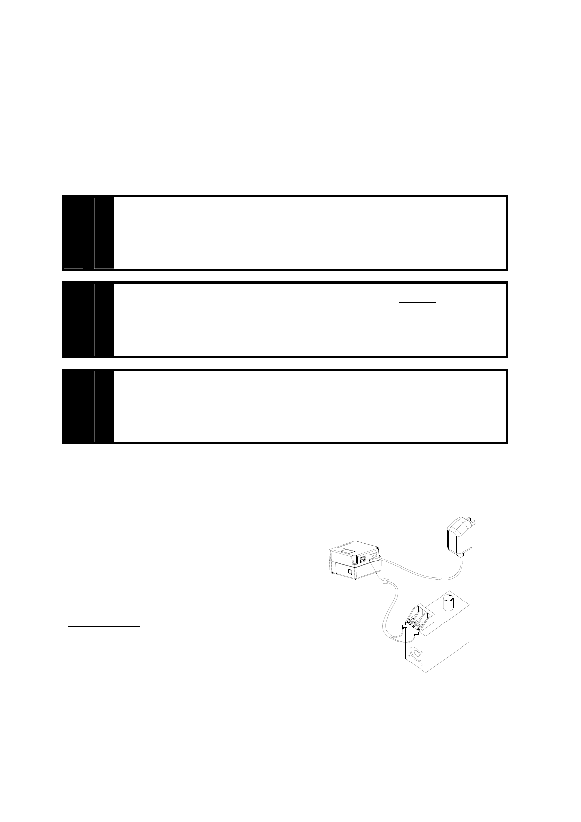
Power up Receiver
The receiver is powered by plugging into a polarized 120VAC
outlet.
120VAC Plug for Receiver
Receiver
mV Valve
50D0104 RCSTE Rel 0 Feb 10 2006 Page 2 of 7 Ambient Technologies
A Division Of Monessen Hearth Systems
Page 3
Installing Wire
This system comes with an 22 inch pre-assembled wire assembly. Insert the white terminal to the back of the
receiver. The terminal wire block can only be installed one way. Do not force the terminal plug onto the receiver.
Follow the homeowner’s manual for connecting the two (2) 1/4” female spade terminals to the millivolt valve.
For applications longer than 22 inches, use 18 gauge wire, 105ºC rated, with as few splices as possible. Connect to
the two (2) 1/4“ female spade wiring terminals. Wire can be no longer than 20 feet.
Optional 6 hour Shutdown
1. The receiver comes preset from the factory with a 6 hour shutdown from its last ON operation. This is done
to prevent the appliance from continuing to run if unattended.
2. You may disable this feature if you wish. To disable, change the receiver privacy (DIP) switch #1 ONLY to
the OFF position. Make sure the transmitter privacy (DIP) switches are set the same to the receiver. Follow
the instructions on how to set the privacy (DIP) switch setting.
3. By disabling this feature, your appliance may continue to run unattended.
Make sure that the wires do not contact the appliances any place other than at the terminals.
Exposure to temperatures higher than 105C (250ºF) may cause the receiver to malfunction or
fire hazard.
WARNING
Remote Transmitter
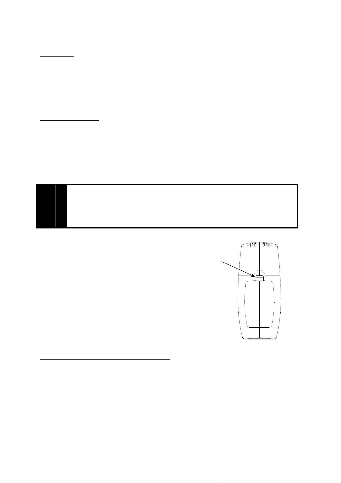
Installing Batteries:
The remote transmitter uses three (3) “AAA” batteries. To install batteries,
1. Press down the battery door tab and lift up and remove the
battery door.
2. Install the batteries as indicated on transmitter.
3. Close the battery door by snapping in place.
4. When three batteries are installed, the transmitter will initialize for 10
seconds and then is ready for use.
5. The batteries should be replaced at least once every 6 months or when the
battery icon indicator flashes.
Setting Privacy (DIP) Switch on Receiver and Transmitter
The remote receiver and transmitter privacy (DIP) switches are preset at the factory. In the event of activation or
interference from other nearby transmissions, reset the code using the following procedure:
1. Slide the code switches on the transmitter or receiver to your choice of ON or OFF position. Switches #1,
#2, #3 and #4 are preset to “ON” for both the transmitter and receiver.
2. The switches on the transmitter and receiver must match in order for the system to work.
3. To check, touch either the On or Off button on the transmitter and the receiver indicator light will blink. If
not repeat step 2.
4. The system is now ready to operate. See optional 6 hour shutdown on receiver section.
Battery
Door Tab
Back of the Transmitter
50D0104 RCSTE Rel 0 Feb 10 2006 Page 3 of 7 Ambient Technologies
A Division Of Monessen Hearth Systems
Page 4

Transmitter
Dip Switch (Default)
ON
DIP
Receiver
DIP
ON
Do not use two (2) or more remote control systems in the same area with the same dip switch
settings, as they will communicate with each other. This may cause the appliances to
malfunction.
WARNING
Reset Button
1. The reset button can be used to reset the transmitter if transmitter is not working properly. The reset button
is located behind the battery door cover. Using a paper clip, press the reset button and the transmitter will
reset and initialize for 10 seconds before it can be used.
OPERATIONS
Transmitter
General
The RCST Remote Control has two (2) operating modes: Manual and Thermostatic.
The control system can be set to temperature ranges between 45°F and 90°F.
The transmitter will operate the remote receiver from 1foot to a maximum of 30 feet.
The distance is reduced when batteries are low or when the receiver is inside a metal
enclosure.
Initial Start-up
1. After initial power up or when RESET button is pressed, the transmitter is
reset. The reset button is located inside the battery door.
2. During system reset, all features of the LCD display will be visible. After one
second, the LCD displays will be initialized. A typical reset display is shown beside.
Note that the temperature scale is degree F.
3. Press On button to select between °C and °F display. It will exit setting mode
automatically after 10 seconds if no key is pressed. The transmitter will send an Off
signal after reset.
4. After reset the transmitter is operating in manual mode. The room temperature is
shown as above.
50D0104 RCSTE Rel 0 Feb 10 2006 Page 4 of 7 Ambient Technologies
A Division Of Monessen Hearth Systems
Page 5

Manual Mode
1. Press the ON button once to turn on the appliance.
2. Press the OFF button to turn it off.
Thermostatic Mode
1. Press the AUTO button to enter the thermostatic mode. “SET” temp icon
will appear on the lower LCD screen
2. In thermostatic mode, press the ON/▲ button or OFF/ ▼ button to set the
desired set temperature.
3. Once the setting is completed, the transmitter will automatically turn on the
fireplace when the room temperature is below the set temperature and turn off the appliance when the
room temperature is above the set temperature within 1 degree.
4. There will be a slight delay in the response of the unit (on/off) to a temperature. Room temperature is
monitored every 3 minutes.
5. Press the Auto button to exit the thermostatic mode (Return to Manual Mode). The “SET” temp icon will
disappear on the lower LCD display. The transmitter will be in the manual on/off mode
.
Low Battery Detection
1. Battery voltage is checked once a minute. When the battery voltage drops to a
certain level, the low-battery warning will come on, and the transmitter will turn
off the appliance. The transmitter will not function anymore until fresh batteries
are installed.
2. When the batteries are low, the LCD shows a low battery indicator. The low
battery warning will be displayed in any mode.
3. The transmitter will not operate with low batteries. Change the battery before the
battery is too weak for normal operation. TURN THE UNIT OFF BEFORE
REPLACING BATTERIES.
Child-Proof Protection
1. Press and hold ON and OFF buttons simultaneously for 3 seconds to enter child-
proof mode.
2. The transmitter will not work until child-proof mode is deactivated by pressing
the ON and OFF buttons simultaneously for 3 seconds again to exit child-proof
mode.
Transmitter Thermal Shutdown
1. If transmitter measures a room temperature exceeding 99 degrees Fahrenheit, the
LCD will display "HI" and the transmitter will turn off the appliance.
2. Transmitter will not function until the room temperature has dropped below 99
degree Fahrenheit.
3. If transmitter measures a room temperature less than 40 degrees Fahrenheit, the
LCD will display “LO” and NO SIGNAL will be sent to turn on the appliance.
50D0104 RCSTE Rel 0 Feb 10 2006 Page 5 of 7 Ambient Technologies
A Division Of Monessen Hearth Systems
Page 6

Receiver
Slide Switch
1. ON position: the system will remain on until the slide switch is placed in the OFF or RS position.
2. RS position: the system will only operate if the remote receiver receives a signal from the transmitter.
3. OFF position, the system is off. The slide switch should be placed in the OFF position if you will be
1. Light your gas appliance following the appliance lighting instructions that come with the appliance.
2. Slide the 3 position button on the remote receiver to the ON position. The main gas flame should ignite.
3. Slide the button to OFF. The flame should extinguish (the pilot light will remain on).
4. Slide the button to RS (the center position), then press the transmitter to turn the system to ON. The main
5. Press the transmitter to turn the system to OFF. The flame should extinguish (the pilot light will remain
away for an extended period of time. If the remote receiver is mounted out of children’s reach, the OFF
position also functions as a safety device by both turning the system off and rendering the receiver
inoperable.
TESTING YOUR NEW REMOTE CONTROL SYSTEM
Confirm that the pilot light is on; it must be in operation for the remote control to operate the main gas
valve. Appliance pilot control knob must be in the ON position. Appliance ON/OFF switch must be in
OFF position.
gas flame should ignite.
on).
TROUBLESHOOTING
Symptom Causes Action
1. Low battery icon on
display on transmitter.
2. Display is blank
3. Display shows “funny”
display
4. Appliance does not
come on.
2. Privacy (DIP) switch setting on
3. Transmitter measures temperature
4. Distance between the transmitter
5. Receiver cannot detect
signal.
2. 120VAC is not connected 2. Connect receiver adaptor to 120VAC
1. Low Battery on Transmitter 1. Replace batteries. Change batteries every 6
months.
2. Check battery installation and replace
batteries.
3. Press Reset button at the back of the
transmitter.
1. Wiring / Electrical Connections 1. Slide the switch to ON, if appliance comes
ON, wiring is not the cause.
2. If appliance does not come on, check wiring
connections.
3. Check to make sure the receiver is plug
into 120 VAC outlets.
1. Make sure the transmitter and receiver have
transmitter does not match receiver
exceeding 99 degrees Fahrenheit
and shows “HI” on LCD display
and receiver is more than 20 feet
1. Receiver is installed in an
enclosure
the same DIP switch settings.
1. Move transmitter to a cooler place and wait
until temperature drops below 99 degree.
1. Make sure the operating distance is less
than 20 feet
1. Make sure the receiver is not located inside
to the tight of an enclosure.
power supply.
50D0104 RCSTE Rel 0 Feb 10 2006 Page 6 of 7 Ambient Technologies
A Division Of Monessen Hearth Systems
Page 7

WARNING: Changes or modifications to this unit not expressly approved by the party responsible for compliance
could void the user’s authority to operate the equipment.
NOTE: This equipment has been tested and found to comply with the limits for a Class B digital device, pursuant to
Part 15 of the FCC Rules. These limits are designed to provide reasonable protection against harmful interference in
a residential installation. This equipment generates, uses and can radiate radio frequency energy and, if not installed
and used in accordance with instructions, may cause harmful interference to radio communications. However, there
is no guarantee that interference will not occur in a particular installation. If this equipment does cause harmful
interference to radio or television reception, which can be determined by turning the equipment off and on, the user
is encouraged to try to correct the interference by one or more of the following measures:
• Reorient or relocate the receiving antenna.
• Increase the separation between the equipment and receiver.
• Connect the equipment into an outlet on a circuit different from that to which the receiver is connected.
• Consult the dealer or an experienced radio/TV technician for help.
WARRANTY
This warranty gives you specific legal rights and you may also have other rights that vary from state to state or
province to province. Answers to any questions regarding our limited warranty may be obtained by writing our
corporate offices.
Ambient Technologies warrants each new Ambient Technologies remote control against any defects that are due to
faulty material or workmanship to the original owner, for a period of five years after the original date of purchase.
This warranty and our liability does not apply to batteries, nor does it include damage to merchandise or the remote
control resulting from accident, alteration, neglect, misuse, improper installation or any other failure to follow
Ambient Technologies installation and operating instructions.
Ambient Technologies agrees to repair or replace at its option any Ambient Technologies remote control under
warranty provided it is returned postage prepaid to our warranty facility in a padded carton within the warranty
period, with proof of the original date of purchase and a brief description of the malfunction. This limited warranty
does not include the cost of removal or re-installation. All Ambient returns must have a return authorization
number from Ambient Technical Support.
Ambient Technologies
149 Cleveland Drive
Paris KY 40361
FOR TECHNICAL SUPPORT
CALL 800-398-6195
50D0104 RCSTE Rel 0 Feb 10 2006 Page 7 of 7 Ambient Technologies
A Division Of Monessen Hearth Systems
 Loading...