

Page 1
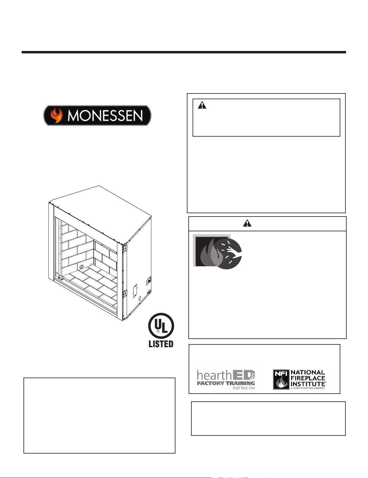
Installation & Owner’s Manual
Installation, Care and Operation
INSTALLER: Leave this manual with party responsible for use and operation.
OWNER: Retain this manual for future reference.
NOTICE: DO NOT discard this manual!
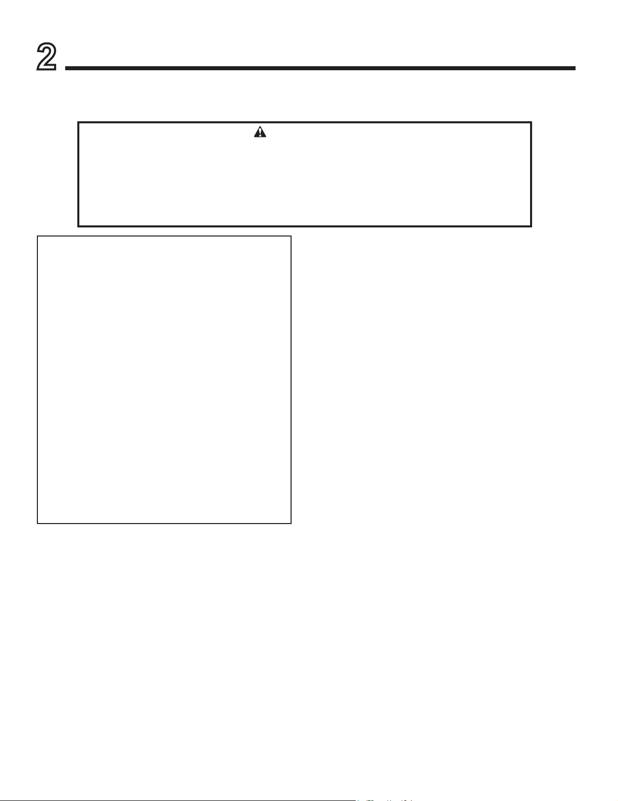
WARNING: If the information in these
instructions is not followed exactly, a re
or explosion may result causing property
damage, personal injury, or death.
Model(s):
LCUF32CR-B
LCUF36CR-B
LCUF42CR-B
• DO NOT store or use gasoline or other am-
mable vapors and liquids in the vicinity of this
or any other appliance.
DO NOT overre. Overring will void your
•
warranty.
• Comply with all minimum clearances to combustibles as specied. Failure to comply may
cause house re.
WARNING
HOT SURFACES!
Glass and other surfaces are hot during
operation AND cool down.
Hot glass will cause burns.
• DO NOT touch glass until it is cooled
• NEVER allow children to touch glass
• Keep children away
• CAREFULLY SUPERVISE children in same room as
replace.
• Alert children and adults to hazards of high temperatures.
High temperatures may ignite clothing or other ammable
materials.
• Keep clothing, furniture, draperies and other ammable
materials away.
VENT FREE FIREBOX
Carefully review the instructions supplied
with the decorative type unvented room
heater for the minimum fireplace size
requirement.
DO NOT INSTALL AN APPLIANCE IN THIS
FIREBOX UNLESS THIS FIREBOX MEETS
THE MINIMUM DIMENSIONS REQUIRED
FOR THE INSTALLATION.
Monessen • LCUF32/36/42 Installation and Operating Manual • 4607-900 • Rev D • 3/21
Installation and service of this appliance should be performed by
qualied personnel, Hearth & Home Technologies recommends
HHT Factory Trained or NFI certied professionals.
For use with a listed gas-red unvented room
heater not to exceed 40,000 BTU/hr. Do not
build a wood re.
1
Page 2

Safety Alert Key:
• DANGER! Indicates a hazardous situation which, if not avoided will result in death or serious injury.
• WARNING! Indicates a hazardous situation which, if not avoided could result in death or serious injury.
• CAUTION! Indicates a hazardous situation which, if not avoided, could result in minor or moderate injury.
• NOTICE: Indicates practices which may cause damage to the replace or to property.
Table of Contents
Installation Standard Work Checklist 3
1 Welcome
A. Congratulations 4
B. LIMITED LIFETIME WARRANTY 5
►
2 Important Safety and Operating Information 7
3 General Installation Information
Before You Start 9
Check Parts 9
Tools Needed for Installation 9
4 Firebox and Framing Dimensions
Dimensions 10
5 Hearth Dimensions and Firebox Locations
Hearth Dimensions 11
Firebox Locations 11
6 Clearances 12
7 Fireplace, Canopy and Gas Line Installation
Securing & Leveling Appliance 14
Canopy Installation 14
Gas Connections 15
8 Combustion Air 16
Install Model AK22 Combustion Air Assembly 16
9 Optional Equipment
Forced Air Kit 18
Panels 18
Accent Light Kit 18
Optional Door Kit 18
10 Service Parts
Service Parts Lists 19
►
2
Monessen • LCUF32/36/42 Installation and Operating Manual • 4607-900 • Rev D • 3/21
Page 3
ATTENTION INSTALLER:
Follow this Standard Work Checklist
This standard work checklist is to be used by the installer in conjuction with, not instead of, the instructions contained in this installation
manual.
Customer:
Lot/Address
Model (circle one): LCUF32CR-B LCUF36CR-B
LCUF42CR-B
Date Installed:
Location of Fireplace:
Installer:
Dealer/Distributor Phone No:
Serial No:
WARNING! Risk of Fire or Explosion! Failure to install fireplace acording to these instructions can lead to a fire or
explosion.
Fireplace Install
Wiring has been installed if necessary.
Verified clearances to combustibles. (Pg. 11)
Fireplace is leveled and secured. (Pg. 13)
Hearth extension size/height decided. (Pg. 12)
Outside air kit installed. (Pg 15) Optional
Finishing
Combustible materials not installed in non-combustible areas.
Verified all clearances meet installation manual requirements.
Mantels and wall projections comply with installation manual requirements.
Hearth extension installed per manual requirements.
Fireplace Setup
All packaging and protective materials removed.
Refractory installed correctly.
Firescreen installed properly.
Manual bag and all of its contents are removed from the fireplace and given to the
party responsible for use and operation.
Blower kit installed properly. (Optional)
Light kit installed properly. (Optional)
Door kit installed properly. (Optional)
YES IF NO, WHY?
Hearth & Home Technologies recommends the following:
• Photographing the installation and copying this checklist for your file.
• That this checklist remain visible at all times on the fireplace until the installation is complete.
Comments: Further description of the issues, who is responsible (Installer/Builder/Other Trades, etc.) and corrective action needed:
Comments communicated to party responsible
__________________________ by ______________________on _________
(Builder/Gen. Contractor) (Installer) (Date)
4607-902 • Rev A • 4/18
Monessen • LCUF32/36/42 Installation and Operating Manual • 4607-900 • Rev D • 3/21
3
Page 4
Welcome
1
Read this manual before installing or operating this replace.
Please retain this manual for future references.
A. Congratulations
Congratulations on selecting a Monessen Hearth rebox. It
is designed to provide the utmost in safety, reliability, and
efciency.
As the owner of a new replace, you'll want to read and
carefully follow all of the instructions contained in this manual. Pay special attention to all Cautions and Warnings.
Local Dealer Information
This manual should be retained for future reference. We
suggest that you keep it with your other important documents and product manuals.
Your new Monessen vent free rebox will give you years of
durable use and trouble-free enjoyment. Welcome to the
Monessen family of replace products!
Monessen is a registered trademark of Hearth & Home
Technologies.
DEALER: Fill in
your name, address,
phone and email
information here and
replace information
below.
Fireplace Information:
Brand: ________________________________________________ Model Name: ___________________________
Serial Number: __________________________________________ Date Installed: __________________________
Dealer Name: ________________________________________________________
Address: ____________________________________________________________
____________________________________________________________
Phone: _____________________________________________________________
Email: _____________________________________________________________
4
Monessen • LCUF32/36/42 Installation and Operating Manual • 4607-900 • Rev D • 3/21
Page 5
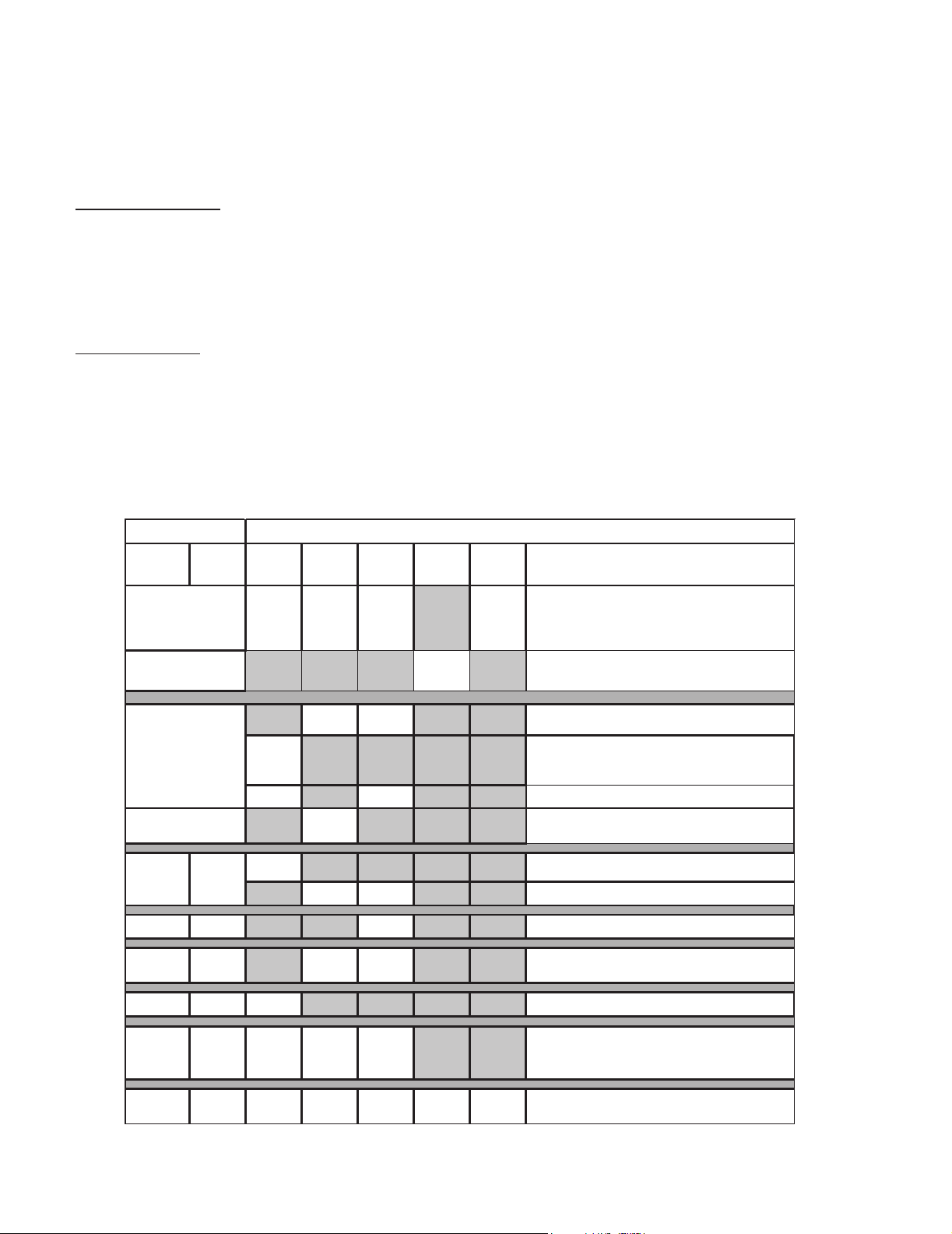
B. LIMITED LIFETIME WARRANTY
recoverable under this Warranty is limited to the purchase price of the Product. This Warranty is transferable from the original purchaser
Component
►
Hearth & Home Technologies LLC
LIMITED LIFETIME WARRANTY
Hearth & Home Technologies LLC (“HHT”) extends the following warranty for HHT gas, wood, pellet and electric hearth appliances
(each a “Product” and collecvely, the “Product(s)”) and certain component parts set forth in the table below (“Component Part(s)”)
that are purchased from a HHT authorized dealer or distributor.
WARRANTY COVERAGE:
HHT warrants that the Products and their Component Parts will be free from defects in materials and workmanship for the applicable
period of Warranty coverage set forth in the table below (“Warranty Period”). If a Product or Component Parts are found to be
defecve in materials or workmanship during the applicable Warranty Period, HHT will, at its opon, repair the applicable Component
Part(s), replace the applicable Component Part(s), or refund the purchase price of the applicable Product(s). The maximum amount
to subsequent owners, but the Warranty Period will not be extended in duraon or expanded in coverage for any such transfer. This
Warranty is subject to condions, exclusions, and limitaons as described below.
WARRANTY PERIOD:
Warranty coverage begins at the date of installaon. In the case of new home construcons, Warranty coverage begins on the date of
rst occupancy of the dwelling or six months aer the sale of the Product(s) by an independent, authorized HHT dealer or distributor,
whichever occurs earlier. However, the Warranty coverage shall commence no later than 24 months following the date of Product
shipment from HHT, regardless of the installaon or occupancy date.
The term “Lifeme” in the table below is dened as: 20 years from the beginning date of warranty coverage for gas appliances, and 10
years from the beginning date of warranty coverage for wood and pellet appliances. These me periods reect the minimum expected
useful lives of the designated Component Parts under normal operang condions.
Warranty Period HHT Manufactured Appliances and Venting
Parts
5 years 1 year
6 years 3 years X Catalysts
7 years 3 years X X Manifold tubes, HHT Chimney and Terminations
Labor Gas Pellet Wood Electric Venting Component Parts Covered by this Warranty
All parts including handles, external enameled
components and other material except as covered by
2 Years
2 years
3 years X
X
X X Molded Refractory Panels, Glass Liners
X Vent Free Burners, Vent Free Logs
X1 Year X X X
X
X X
X X Castings, Medallions and Baffles
Warranty Conditions, Warranty Exclusions, and
All parts except as covered by Warranty Conditions,
Warranty Exclusions, and Warranty Limitations listed
Igniters, Auger Motors, Electronic Components, and
Electrical components limited to modules, remotes/wall
switches, valves, pilots, blowers, junction boxes, wire
harnesses, transformers and lights (excluding light bulbs)
Warranty Limitations listed
Glass
Firepots, burnpots, mechanical feeders/auger
assemblies
10 years 1 year X Burners, logs and refractory
Limited
Lifetime
1 Year
4021-645L 10/20
3 years X X X
None
X X X X X All purchased replacement parts
Firebox and heat exchanger, FlexBurn® System
(engine, inner cover, access cover and fireback)
Monessen • LCUF32/36/42 Installation and Operating Manual • 4607-900 • Rev D • 3/21
Page 1 of 2
5
Page 6

B. Limited Lifetime Warranty (continued)
4021-645L 10/20
WARRANTY CONDITIONS:
• Because HHT cannot control the quality of any Products sold by unauthorized sellers, this Warranty only covers Products that are
purchased through an HHT authorized dealer or distributor unless otherwise prohibited by law; a list of HHT authorized dealers
is available on the HHT branded websites.
• This Warranty is only valid while the applicable Product remains at the site of original installaon.
• This Warranty is only valid in the country in which the HHT authorized dealer or distributor that sold the applicable Product is
authorized to sell applicable Product.
• Contact your installing distributor or dealer for Warranty service. If the installing dealer or distributor is unable to provide
necessary parts, contact the nearest HHT authorized dealer or supplier. Addional service fees may apply if you are seeking
Warranty service from a dealer other than the dealer from whom you originally purchased the applicable Product.
• No HHT consumer should bear cost of warranty service or costs incurred while servicing warranty claims (i.e., travel, gas, or
mileage) when the service is performed within the terms of this Warranty. Check with your dealer or distributor in advance for
any costs to you when arranging a warranty call. Travel and shipping charges for parts are not covered by this Warranty.
WARRANTY EXCLUSIONS:
This Warranty does not cover the following:
• Changes in surface nishes as a result of normal use. As a heang appliance, some changes in color of interior and exterior surface
nishes may occur. This is not a aw and is not covered under the Warranty.
• Damage to printed, plated, or enameled surfaces caused by ngerprints, accidents, misuse, scratches, melted items or other
external sources and residues le on the plated surfaces from the use of abrasive cleaners or polishes.
• Repair or replacement of parts that are subject to normal wear and tear during the Warranty Period are not covered. These parts
include: paint, wood and pellet gaskets, rebricks, grates, ame guides, baeries and the discoloraon of glass.
• Minor expansion, contracon, or movement of certain parts causing noise. These condions are normal and complaints related to
this noise are not covered by this Warranty.
• Damages resulng from: (1) failure to install, operate, or maintain the applicable Product in accordance with the installaon
instrucons, operang instrucons, and lisng agent idencaon label furnished with the applicable Product; (2) failure to
install the applicable Product in accordance with local building codes; (3) shipping or improper handling; (4) improper operaon,
abuse, misuse, connued operaon with damaged, corroded or failed components, accident, or improperly/incorrectly performed
repairs; (5) environmental condions, inadequate venlaon, negave pressure, or draing caused by ghtly sealed construcons,
insucient make-up air supply, or handling devices such as exhaust fans or forced air furnaces or other such causes; (6) use of fuels
other than those specied in the operaon instrucons; (7) installaon or use of components not supplied with the applicable
Product or any other components not expressly authorized and approved by HHT; (8) modicaon of the appliance not expressly
authorized and approved by HHT in wring; and/or (9) interrupons or uctuaons of electrical power supply to the applicable
Product.
• Non-HHT venng components, hearth connecons or other accessories used in conjuncon with the applicable Product.
• Any part of a pre-exisng replace system in which an insert or a decorave gas applicable Product is installed.
• HHT’s obligaon under this Warranty does not extend to the Product’s capability to heat the desired space. Informaon is provided
to assist the consumer and the dealer in selecng the proper Product for the applicaon. Consideraon must be given to the
Product locaon and conguraon, environmental condions, insulaon and air ghtness of the structure.
This warranty is void if:
• The applicable Product has been over-red, operated in atmospheres contaminated by chlorine, uorine, or other damaging
chemicals. Over-ring can be idened by, but not limited to, warped plates or tubes, deformaon/warping of interior cast iron
structure or components, rust colored cast iron, bubbling, cracking and discoloraon of steel or enamel nishes.
• The applicable Product is subjected to prolonged periods of dampness or condensaon.
• There is any damage to the applicable Product due to water or weather damage which is the result of, but not limited to, improper
chimney or venng installaon.
LIMITATIONS OF REMEDIES AND LIABILITY:
• EXCEPT TO THE EXTENT PROVIDED BY LAW, HHT MAKES NO EXPRESS WARRANTIES OTHER THAN THE WARRANTY SPECIFIED
HEREIN. The owner’s exclusive remedy and HHT’s sole obligaon under this Warranty or in contract, tort or otherwise, shall be
limited to replacement of the Component Part(s), repair of the Component Part(s), or refund of the original purchase price of the
applicable Product(s), as specied above; provided, however, that (i) if HHT is unable to provide replacement of the Component
Part(s) and repair of the Component Part(s) is not commercially praccable or cannot be mely made, or (ii) the customer is
willing to accept a refund of the purchase price of the applicable Product(s), HHT may discharge all such obligaons by refunding
the purchase price of the applicable Product. In no event will HHT be liable for any incidental or consequenal damages caused
by defects in the applicable Product. Some States do not allow the exclusion or limitaon of incidental or consequenal damages,
so the above limitaon or exclusion may not apply to you. This Warranty gives you specic legal rights and you may also have
other rights which vary from State to State. THE DURATION OF ANY IMPLIED WARRANTY IS LIMITED TO DURATION OF THE
EXPRESSED WARRANTY SPECIFIED ABOVE FOR THE APPLICABLE PRODUCT. Some States do not allow limitaons on how long an
implied warranty lasts, so the above limitaon may not apply to you.
Page 2 of 2
6
Monessen • LCUF32/36/42 Installation and Operating Manual • 4607-900 • Rev D • 3/21
Page 7
Important Safety and Operating Information
2
INSTALLER
Please leave these instructions with the appliance.
WARNING!
• Any change to this heater or its controls can be dangerous.
• Improper installation or use of the heater can cause serious injury or death from re, burns,
explosion or carbon monoxide poisoning.
• Do not allow fans to blow directly into the rebox. Avoid any drafts that alter burner ame patterns.
• Do not use a blower insert, heat exchanger insert or other accessory, not approved for
use with this heater where applicable.
1. Due to high temperatures, the rebox should be
located out of trafc and away from furniture and
draperies.
2. Children and adults should be alerted to the hazard
of high surface temperature and should stay away
to avoid burns or clothing ignition.
3. Young children should be carefully supervised when
they are in the same room with the rebox.
4. Do not place clothing or other ammable material
near the replace when the rebox is in use.
5. Any safety screen or guard removed for servicing,
must be replaced prior to operating a heater within
the rebox.
6. Installation and repair should be done by a qualied
service person.
7. To prevent malfunction and/or sooting, an unvented
gas heater/rebox should be cleaned at least annually by a professional service person. More frequent
cleaning may be required due to excessive lint from
carpeting, etc. It is imperative that control compartments, burners and circulating air passageways be
kept clean.
8. CARBON MONOXIDE POISONING: Early signs of
carbon monoxide poisoning are similar to the u with
headaches, dizziness and/or nausea. If you have these
signs, obtain fresh air immediately. Have the heater
serviced as it may not be operating properly.
9. The installation must conform with local codes or, in
the absence of local codes, with the National Fuel Gas
Code, ANSI Z223.l/NFPA54.
10. This unit complies with ANSI Z21.91-2017 ventless
rebox enclosures for gas-red unvented decorative
room heaters.
11. Do not install the unvented heater in a bathroom.
12. Do not install the unvented heater in a bedroom unless
the maximum input rating is equal to or less than
10,000 Btu/hr.
OWNER
Please retain these instructions for future reference
13. Correct installation of the ceramic ber logs, proper
location of the heater, and annual cleaning are necessary to avoid potential problems with sooting. Sooting,
resulting from improper installation or operation, can
settle on surfaces outside the replace. See log placement instructions for proper installation.
14. Avoid any drafts that alter burner ame patterns. Do not
allow fans to blow directly into replace. Do not place
a blower inside burn area of rebox. Ceiling fans may
create drafts that alter burner ame patterns. Sooting
and improper burning will occur.
15. CAUTION: Candles, incense, oil lamps, etc. produce
combustion byproducts including soot. Vent free
appliances will not lter or clean soot produced by
these types of products. In addition, the smoke and/
or aromatics (scents) may be re-burnt in the vent free
appliance which can produce odors. It is recommended
to minimize the use of candles, incense, etc. while the
vent free appliance is in operation.
16. An unvented gas-red heater uses air (oxygen) from
the room in which it is installed. Provisions for adequate
combustion and ventilation air must be provided. See
installation guidelines.
17. Keep room area clear and free from combustible materials, gasoline and other ammable vapors and liquids.
18. Unvented gas heaters are a supplemental zone heater.
They are not intended to be a primary heating appliance.
19. Unvented gas heaters emit moisture into the living
area. In most homes of average construction, this
does not pose a problem. In houses of extremely
tight construction, additional mechanical ventilation is
recommended.
20. During manufacturing, fabricating and shipping, various
components of this appliance are treated with certain
oils, lms or bonding agents. These chemicals are not
harmful but may produce annoying smoke and smells
as they are burned off during the initial operation of the
appliance; possibly causing headaches, or eye or lung
irritation. This is a normal and temporary occurrence.
.
Continued on page 7
Monessen • LCUF32/36/42 Installation and Operating Manual • 4607-900 • Rev D • 3/21
7
Page 8

Continued from page 6
The initial break-in operation should last two to three
hours with the burner at the highest setting. Provide
maximum ventilation by opening windows or doors to
allow odors to dissipate. Any odors remaining after this
initial break-in period will be slight and will disappear
with continued use.
21. Input ratings are shown in BTU per hour and are for
elevations up to 2,000 feet. For elevations above 2,000
feet, input ratings should be reduced 4 percent for each
1,000 feet above sea level. Refer to the National Fuel
Gas Code.
22. The appliance and its main gas valve must be disconnected from the gas supply piping system during any
pressure testing of that system at test pressures in
excess of 1/2 psig (3.5 kPa).
23. The appliance must be isolated from the gas supply
piping system by closing its equipment shutoff valve
during any pressure testing of the gas supply piping
system at test pressures equal to or less than 1/2 psig
(3.5 kPa).
24. Do not use this room heater if any part has been under
water. Immediately call a qualied service technician
to inspect the room heater and to replace any part of
the control system and any gas control which has been
under water.
25. Never burn solid fuels in a replace where a unvented
room heater is installed.
26. Always have a replace screen in place when the
appliance is in operation, and unless other provisions
for combustion air are provided, the screen shall have
an opening(s) for induction of combustion air.
27. Do not ll spaces around the rebox with insulation or
other materials. These spaces must be maintained to
prevent the rebox from coming in contact with combustible materials.
WARNING!
Do not attempt to burn solid wood fuels, vented
gas log sets, or any other combustible in this
unvented rebox. Also, do not install a vent
free gas log set in this rebox if the minimum
clearance and height requirements of the log
set are too large for the rebox.
Notice: Illustrations shown in this manual reect
“typical” installations with nominal dimensions and
are for design and framing reference only. Actual
installations may vary due to individual design
preferences. However, always maintain minimum
clearances to combustible materials and do not
violate any specic installation requirements.
WARNING!
Never connect unit to private (non-utility)
gas wells. This gas is commonly known as
wellhead gas.
IMPORTANT
Please read the following information
carefully:
It is normal for replaces fabricated of steel
to give off some expansion and/or contraction
noises during the startup and cool down cycle.
Similar noises are found with your furnace
heat exchanger or car engine.
8
Monessen • LCUF32/36/42 Installation and Operating Manual • 4607-900 • Rev D • 3/21
Page 9

General Installation Information
3
The new LCUF32CR-B, LCUF36CR-B, AND LCUF42CRB are vent free reboxes. They feature a self contained
heat-circulating system.
This installation manual will enable you to obtain a safe,
efcient and dependable installation of your vent free
rebox system.
Do not alter or modify the rebox or its components under
any circumstances. Any modication or alteration of the
rebox system, including but not limited to the rebox and
accessories, may void the warranty, listings and approvals
of this system and could result in an unsafe and potentially
dangerous installation.
BEFORE YOU START
Carefully inspect the contents for shipping damage. If any
parts are missing or damaged, immediately inform the
dealer from whom you purchased the appliance. Do not
attempt to install any part of the appliance unless you have
all the parts in good condition.
Note: If using a blower or light kit, electrical
con nec t ion s sho uld be made prior t o the rebox be ing
enclosed by the nished walls.
MAKE SURE YOU HAVE RECEIVED ALL
PARTS
Verify contents to ensure all parts have been received.
The following should be included:
1. Vent Free Gas Firebox
2. Canopy
3. Installation and Operating Instructions
In planning the installation for the appliance it is necessary
to determine where the unit is to be installed and whether
optional accessories are desired. Gas supply piping should
also be planned. The following steps represent the normal
sequence of installation. Each installation is unique, however, and might require a different sequence.
1. Position rebox prior to framing or into prepared framing.
2. The canopy supplied with the unit must be installed.
See Canopy Installation on page 13.
3. Field wire main power supply to models with fan or light
kit. (Electrical connections should only be performed by
an experienced, licensed /certied tradesman).
4. Plumb gas line. (Gas connections should only be performed by an experienced, licensed/certied tradesman).
5. Install vent free gas log heater per the instructions
provided with the vent free gas log heater.
6. Complete nish wall material, surround and optional
hearth extension to your individual taste.
Notice: Illustrations displayed in this manual reect
“typical” installations with minimal dimensions, and are
or design and framing reference only. Actual installations may vary due to individual design preferences.
However, always maintain minimum clearances to
combustible materials and do not violate any specic
installation requirements.
WHAT YOU WILL NEED FOR INSTALLATION
TOOLS and BUILDING SUPPLIES
• Phillips screwdriver • Square
• Framing materials • Hammer
• Saw and / or saber saw • Tee joint
• Level • Pipe wrench
• Measuring tape • Pliers
• Electric drill and bits
• Fireplace surround materials (noncombustible)
• Caulking material (noncombustible)
• Wall nishing materials
• Piping complying with local codes
• Pipe sealant approved for use with propane/L.P.G.
(resistant to sulfur compounds)
Refer to the installation instructions provided with the log
sets for items required for log set installation.
Monessen • LCUF32/36/42 Installation and Operating Manual • 4607-900 • Rev D • 3/21
9
Page 10

Firebox and Framing Dimensions
4
Rough
Opening
Depth
E
G
E
F
Rough
Opening
Height
37-3/4"
23"
22-3/4"
D - Rough Opening Width
I
3"
B
A
C
5-1/4"
30-3/4"
1-3/8"
3"
37-1/4"
9-3/8"
2-7/8"
1/2" - 5/8"
25-1/4"
6-3/4"
9-3/8"
13-1/8"
20-3/8"
Figure 4.1 Firebox and Framing Dimensions
Ref. LCUF32CR-B LCUF36CR-B LCUF42CR-B
A 38" 42" 48"
B 32" 36" 42"
C 26" 30" 36"
D - Chase Installation 38-1/2" 42-1/2" 48-1/2"
D - Recessed Installation 38-3/4" 42-3/4" 48-3/4"
E 50-1/4" 52-7/8" 57-1/4"
F 71-1/8" 75-1/8" 80-7/8"
G 35-1/4" 37-1/4" 40-1/8"
10
Monessen • LCUF32/36/42 Installation and Operating Manual • 4607-900 • Rev D • 3/21
Page 11

Hearth Dimensions and Firebox Locations
5
C
D
A
Figure 5.1 Minimum Hearth Dimensions
Ref. LCUF32CR-B LCUF36CR-B LCUF42CR-B
A 29 3/4” 33 3/4” 39 3/4”
B 15 1/4” 15 1/4” 15 1/4”
C 21 5/8” 25 5/8” 31 5/8”
D 29 3/4” 29 3/4” 29 3/4”
E 28 1/4” 28 1/4” 28 1/4”
FIREBOX LOCATION
Carefully select the best location for installation of your
vent free rebox. The following factors should be taken
into consideration:
E
B
• Clearance to side wall, ceiling, woodwork and windows.
See “Clearances/Height Requirements in Section 6.
Minimum clearances to combustibles must be main-
tained.
• Location must not be affected by drafts caused by
kitchen exhaust fans, ceiling fans, return air registers for
forced air furnaces / air conditioners, windows or doors.
• Installation must provide adequate ventilation and com-
bustion air.
• Location should be out of high trafc or windy or drafty
areas.
• DO NOT INSTALL WHERE CURTAINS, FURNITURE,
CLOTHING OR OTHER FLAMMABLE OBJECTS ARE
LESS THAN 42" FROM FRONT OF HEATER.
• Never obstruct the front opening of the vent free rebox
or restrict the ow of combustion and ventilation air.
• Minimize modications to existing construction. Refer
to Figure 5.2 for location suggestions.
• Do not install in the vicinity where gasoline or other
ammable liquids may be stored. The vent free rebox
must be kept clear and free from these combustible
materials.
Monessen • LCUF32/36/42 Installation and Operating Manual • 4607-900 • Rev D • 3/21
Figure 5.2 Location of Firebox
11
Page 12

Clearances
6
Ensure that minimum clearances shown in Figures 6.1
through 6.3 are maintained. Left and right clearances are
determined when facing the front of the rebox.
Follow these instructions carefully to ensure safe installation. Failure to follow these requirements may create a
re hazard.
1. Sidewall clearances: The clearance from the inside
of the appliance to any combustible wall should not be
less than 6". See Figure 6.1.
2. Ceiling clearance: The ceiling must be at least 42"
from the top of the rebox opening. See Figure 6.1.
3. Back wall clearance: The appliance may be placed
against a combustible back wall.
42"
Minimum
6"
Minimum
Combustible Material
Can Contact Top of
Fireplace
Non-combustible
Material Only if
Needed to Cover
Radiant Top Face
Combustible
Non-combustible
12”
10”
E
8”
D
6”
C
2¹⁄₂”
B
A
Seal joint with noncombustible sealant to
prevent heat from being
drawn into the wall cavity.
A B C D E
in. 12 14 15.50 16.75 18
mm 305 356 394 425 457
in. 0 0 1.50 2.75 4
mm 0 0 38 70 102
6"
Minimum
Figure 6.1 Clearance and Height Requirements
4. Mantel clearances: If a combustible mantel is installed,
it must meet the clearance requirements as shown in
Figures 6.2 & 6.3.
WARNING! Risk of Fire! Comply with all minimum clear-
ances as specied. Framing closer than the minimums
listed must be constructed entirely of non-combustible materials (i.e., steel studs, concrete board, etc.).
NOTE: The canopy supplied with the unit must be installed
for correct mantel clearances. See canopy installation on
page 13.
Figure 6.2 Mantel Clearances
Fireplace
B
Hood
A
Top View
Grid represents 1/2" x 1/2"
Combustible
in. 3 1 4
mm 76 25 102
Non-combustible
in. 0 6 6
mm 0 152 152
6”
A B C
Finish Wall
Combustible
Material Area
45°
C
12
Figure 6.3 Mantel Leg Clearance
Monessen • LCUF32/36/42 Installation and Operating Manual • 4607-900 • Rev D • 3/21
Page 13

5. Floor clearance: This inner chamber rebox oor must
be installed at least 1" above any combustible ooring
material, such as carpeting or asphalt tile, which is closer
than 14" to the base of the rebox. See Figure 6.4.
Or
The inner chamber rebox oor may be installed nearer to
the oor if a minimum of 14" of noncombustible material
such as slate or marble is installed between the base of
the rebox and the combustible ooring. See Figure 6.5.
Combustible
Material
Firebox framing can be built before or after the appliance is
set in place. Construct rebox framing following Figure 4.1
for your specic installation requirements. Refer to Figure
4.1 on page 9 for rebox dimensions. The framing headers
may rest on the top of the rebox standoffs.
The rebox may be installed directly on a combustible oor
or raised on a platform of an appropriate height. When
the rebox is installed directly on carpeting, tile, or other
combustible material, other than wood ooring, the rebox
shall be installed on a metal or wood panel extending the
full width and depth of the enclosure.
The classication “non-combustible material” includes, but
is not limited to: stone, brick, and mortar. Non-com-bustibles are safe to overlay the black-painted metal face, including radiant plates, and do not pose a re hazard. Any
non-combustible nish material must not extend past or
interfere with the replace opening.
The classication “combustible material” includes, but is
not limited to: plywood, drywall, and particle board. Combustible materials may contact the sides, bottom, or back
of the rebox. Do not overlay the black-painted face with
combustible materials.
1" Minimum
Figure 6.4 Minimum Clearance Above Combustible Flooring
Can be Less
Than 1"
14” Minimum
Noncombustible
Material
WARNING!
Do not ll spaces around rebox with insulation
or other materials. This could cause a re.
WARNING!
The fireplace must be installed giving full
consideration to the clearance and height
requirements identied in this manual.
Figure 6.5 Minimum Clearance Above Combustible Flooring with
Noncombustible Material Installed at Base of Fireplace
Monessen • LCUF32/36/42 Installation and Operating Manual • 4607-900 • Rev D • 3/21
13
Page 14

7
Fireplace, Canopy and Gas Line Installation
SECURING AND LEVELING THE APPLIANCE
1. Bend out the nailing anges located on each side of the
rebox.
2. Slide the rebox into prepared framing or position rebox
in its nal position and frame later.
3. Level the rebox by checking the top edge of the rebox.
Shim if necessary.
4. Anchor rebox to the side framing members using 8d
nails or other suitable fasteners. Figure 7.1
5. The canopy must be installed for safe operation of the
rebox. See instructions below.
Nail Sides Through Nailing Flanges
Front Face
Screws
Figure 7.2 Canopy Installation
Canopy
Figure 7.1 Location of Nailing Flanges
CANOPY INSTALLATION
A canopy is furnished with each rebox and MUST be installed for safe operation.
1. Locate three (3) screws at the front edge of face (one
at each end, and one in the center.)
2. Loosen screws slightly, slide canopy slots against
screws and tighten in place. Figure 7.2
WARNING!
The rebox canopy must not be modied or
replaced with a canopy that may be provided
with the vent free decorative room heater.
WARNING!
Close replace screen panel before operating a
decorative type vent free room heater.
14
Monessen • LCUF32/36/42 Installation and Operating Manual • 4607-900 • Rev D • 3/21
Page 15

GAS CONNECTIONS
WARNING!
Plumbing connections should only be
performed by a qualied, licensed plumber.
Main gas supply must be off when plumbing
gas line to replace or performing service.
Consult all local codes. All gas piping must be installed to
comply with local codes, or in the absence of local codes,
with the latest edition of the National Fuel Gas Code ANSI
Z223.1/NFPA54.
The 1/2" gas line may enter either from the left side or right
side of the rebox. Gas access holes are provided on both
sides of the rebox.
A listed manual shutoff valve must be installed upstream of
the appliance. A union tee and plugged 1/8" NPT pressure
tapping point should be installed upstream of the appliance.
IMPORTANT: Install main gas valve (equipment shutoff
valve) in an accessible location. The main gas valve is
for turning on or shutting off the gas to the replace.
A sediment trap may be upstream of the heater to prevent
moisture and contaminants from passing through trap to
the heater controls and burners. Failure to do so could
prevent the heater from operating reliably. Consult applicable codes.
An external regulator must be used on all propane/L.P.G.
heaters, in addition to the regulator tted to the heater, to
reduce the supply tank pressure to 13" w.c. (maximum).
Any copper tubing used to supply propane / L.P.G. from
the tank must be internally tinned.
NOTE: When connecting propane / L.P.G. vent free
room heaters, you must use pipe sealant resistant to
propane / L.P.G.
IMPORTANT: Hold heater regulator with a wrench to
prevent movement when connecting to inlet piping.
Check gas type: The gas supply must be the same as
stated on the heater’s rating plate. If the gas supply
is different, DO NOT INSTALL THE HEATER. Contact
your dealer for the correct model.
WARNING!
Connecting directly to an unregulated propane/
L.P.G. tank can cause an explosion.
WARNING!
Do not connect directly to natural gas 1/2 PSI or
2 PSI systems. Always make sure natural gas
pressure is regulated 10.5 w.c. (maximum before
operating the unit).
Notice: After completing connection, test all gas joints
from the gas meter to the gas heater regulator for leaks.
Using soap and water solution or a gas sniffer. DO NOT
USE AN OPEN FLAME.
Monessen • LCUF32/36/42 Installation and Operating Manual • 4607-900 • Rev D • 3/21
15
Page 16

Combustion Air
8
AK22 INSTALLATION
Note: The AK22 is an optional accessory that can be used
to bring in fresh air. Use of the AK22 is not required for
operation unless specied by local codes.
1. Locate combustion air assembly at an exterior location
which is not likely to be accidentally blocked in any manner. Locate assembly a min. of 12" above the snow line
to prevent blockage by snow accumulation.
2. Never mount the combustion air inlet assembly in a garage or storage area where combustible fumes such as
gasoline might be drawn into the replace.
3. Combustion air can be drawn from the crawl space under
a house when an adequate supply of air is provided by
open ventilation.
4. CAUTION: Do not take combustion air from attic space
or garage space.
5. Locate air supply inlet at least 3' away from any appliance
vent terminal.
6. Avoid extremely long runs and numerous turns in the duct
leading from the replace to the combustion air assembly.
These conditions increase the resistance to the free ow
of air through the duct. Refer to Figures 8.1 through 8.4
for methods of installing the outside air for combustion
assemblies.
Inlet Grille
15' Max.
Figure 8.2 Concrete Slab Installation (Optional Outside Air Runs)
in Soft
(Overhang)
Above
Snow
Level
Ground
Level
Figure 8.1 Basement Installation
NOTE: Fireplace model in illustrations may not be
representative of your appliance.
Duct
Extended
to Miss
Joist
To Outside Wall
Figure 8.3 Installation Above Basement or Crawl Space
16
Monessen • LCUF32/36/42 Installation and Operating Manual • 4607-900 • Rev D • 3/21
Page 17

Outside
Wall
Inside Wall
Figure 8.4 45° Corner Installation on Slab Floor
WARNING!
DO NOT remove the cover on side of rebox if
the outside air will not be connected.
NO
Outlet blocked by
snow, leaves, etc.
YES
Clear area
outside
house or in
ventilated
crawl space
Figure 8.5
NO
Garage or
combustible
liquids storage
Factory-built
• Use UL181 Class 1 or Class 0 rigid or flexible ducting.
• Install with short run or mainly straight duct, except small
dip for cold air trap which will help prevent flow of cold air.
• Secure flex duct with screws or wire ties.
fireplace
NO
Attic space
NO
Outlet placed
higher than 3 ft
below the
termination cap
Step by Step Installation
1. Attach the collar to the side of the replace by aligning the
four holes in the collar with the four holes on the replace
side. Attach with the screws provided. See Figure 8.6.
2. Mark and cut out a 4 in. (102 mm) hole in the building
side for air entry. This hole should allow for some framing
(two sides) so the hooded air inlet may be nailed into
position, ush with the building’s outside.
3. Install hooded air inlet in the sidewall of the structure.
4. Assemble the exible duct ID4 or UD4 (not supplied)
between the collar and the hooded air inlet. Secure it
into position with the supplied wire ties.
Figure 8.6
Monessen • LCUF32/36/42 Installation and Operating Manual • 4607-900 • Rev D • 3/21
17
Page 18

Optional Equipment
9
FORCED AIR KIT (BLOTMC)
If you are installing the forced air kit, Model BLOTMC, see
the installation instructions provided with the kit for electrical wiring requirements. The rebox must be connected to
main power supply at time of rebox installation. The blower
must be installed prior to the installation of the vent free
heater. The electrical connections must be made before
the rebox is framed and enclosed in the nished walls.
WARNING!
Electrical connections should only be
performed by a qualied, licensed electrician,
main power must be off when connecting to
main electrical power supply or performing
service.
When installed, the blower must be electrically
grounded in accordance with local codes or in
the absence of local codes, with the National
Electrical Code ANSI/NFPA 70.
PANELS
ACCENT LIGHT KIT (MONAL)
If you are installing the accent light kit, Model MONAL, see
the installation instructions provided with the kit for electrical wiring requirements. The rebox must be connected to
a main power supply at time of rebox installation. The
accent light kit must be installed prior to the installation
of the vent free heater. The electrical connections must
be made before the rebox is framed and enclosed in the
nished walls.
OPTIONAL DOOR KIT (DLR32B, DLR36B,
DLR42B)
If you are installing the optional door kit, see the installation
instrucions provided with the kit.
BMGLR32 Black Magic Glass Kit for LCUF32
BMGLR36 Black Magic Glass Kit for LCUF36
BMGLR42 Black Magic Glass Kit for LCUF42
FBPREMT32 Premium Firebrick Tradional for LCUF32
FBPREMT36 Premium Firebrick Tradional for LCUF36
FBPREMT42 Premium Firebrick Tradional for LCUF42
FBPREMH32 Premium Firebrick Herringbone for LCUF32
FBPREMH36 Premium Firebrick Herringbone for LCUF36
FBPREMH42 Premium Firebrick Herringbone for LCUF42
Optional panels (left, right, and back) may be installed in
the LCUF32CR-B, LCUF36-CR-B, AND LCUF42CR-B. If
panels are replaced, please refer to the rebrick liner kit
installation instructions provided with the panels for more
information.
For LCUF32CR-B, LCUF36-CR-B, AND LCUF42CR-B refractory panels are shipped installed. Once unit is in place,
remove the shipping brackets from the left and right front.
NOTE: Brackets located on top and bottom of side panels
remain in place. See Figure 9.1.
Brackets to be removed before operation.
Figure 9.1
NOTE: When replacing side and back panels to optional
sets, the original refractory hearth brick may be used with
those sets or taken out for bare metal oor.
18
Monessen • LCUF32/36/42 Installation and Operating Manual • 4607-900 • Rev D • 3/21
Page 19

10
Service Parts
►
Service Parts
Lo-Rider
Beginning Manufacturing Date: July 2018
Ending Manufacturing Date: Active
LCUF32CR-B
32” Vent Free Fireplace
1
2
3
6
7
7.1
8
9
10
7.2
7.3
7.4
4
5
11
14
13
12
IMPORTANT: THIS IS DATED INFORMATION. Parts must be ordered from a dealer or distributor.
Hearth and Home Technologies does not sell directly to consumers. Provide model number
and serial number when requesting service parts from your dealer or distributor.
ITEM DESCRIPTION COMMENTS PART NUMBER
1 Nailing Flange
2 Junction Box Cover Plate
3 Plate, Socket
4 Firebox, Rear Access Panel
5 Firebox, Left/Right Access
6 Bracket, Brick Front
7 Refractory
7.1 Refractory, Left Basic
7.2 Refractory, Back Basic
7.3 Refractory, Hearth
7.4 Refractory, Right Basic
8 Canopy
9 Firescreen Rod
10 Screen, Panel (24” W x 30” H)
11 Blower Base
12 Junction Box
13 Clamp Connector
14 Junction Box Cover
Firebox Touch Up Paint
Gloss Black Corvel Aerosol
Qty 4 req 31190
Qty 2 req SRV26548
Qty 2 req SRV4607-144
SRV4607-110
Qty 2 req SRV4607-111
Qty 4 req 71D0124K
SRV4608-701
SRV4608-704
SRV4608-707
SRV4608-702
SRV4612-107
Qty 2 req 26D01232K
Qty 2 req SRV26D4563
SRV4607-143
Plastic SRV4021-013 Y
SRV230-1670
Qty 2 req SRV4604-103
SRV4021-110
71479
Stocked
at Depot
2/21
Monessen • LCUF32/36/42 Installation and Operating Manual • 4607-900 • Rev D • 3/21
19
Page 20

Service Parts
LCUF36CR-B
Lo-Rider
Beginning Manufacturing Date: July 2018
Ending Manufacturing Date: Active
36” Vent Free Fireplace
1
2
3
6
7
7.1
8
9
10
IMPORTANT: THIS IS DATED INFORMATION. Parts must be ordered from a dealer or distributor.
Hearth and Home Technologies does not sell directly to consumers. Provide model number
and serial number when requesting service parts from your dealer or distributor.
ITEM DESCRIPTION COMMENTS PART NUMBER
1 Nailing Flange
2 Junction Box Cover Plate
3 Plate, Socket
4 Firebox, Rear Access Panel
5 Firebox, Left/Right Access
6 Bracket, Brick Front
7 Refractory
7.1 Refractory, Left Basic
7.2 Refractory, Back Basic
7.3 Refractory, Hearth
7.4 Refractory, Right Basic
8 Canopy
9 Firescreen Rod
10 Screen, Panel (24” W x 30” H)
11 Blower Base
12 Junction Box
13 Clamp Connector
14 Junction Box Cover
Firebox Touch Up Paint
Gloss Black Corvel Aerosol
7.2
7.3
7.4
4
5
11
Qty 4 req 31190
Qty 2 req SRV26548
Qty 2 req SRV4607-144
SRV4607-110
Qty 2 req SRV4607-111
Qty 4 req 71D0124K
SRV4608-701
SRV4608-700
SRV4608-705
SRV4608-702
SRV4607-107
Qty 2 req SRV12052
Qty 2 req SRV26D4563
SRV4607-143
Plastic SRV4021-013 Y
SRV230-1670
Qty 2 req SRV4604-103
SRV4021-110
71479
14
13
12
Stocked
at Depot
2/21
20
Monessen • LCUF32/36/42 Installation and Operating Manual • 4607-900 • Rev D • 3/21
Page 21

Service Parts
LCUF42CR-B
Lo-Rider
Beginning Manufacturing Date: July 2018
Ending Manufacturing Date: Active
42” Vent Free Fireplace
1
2
3
6
7
7.1
8
9
10
IMPORTANT: THIS IS DATED INFORMATION. Parts must be ordered from a dealer or distributor.
Hearth and Home Technologies does not sell directly to consumers. Provide model number
and serial number when requesting service parts from your dealer or distributor.
ITEM DESCRIPTION COMMENTS PART NUMBER
1 Nailing Flange
2 Junction Box Cover Plate
3 Plate, Socket
4 Firebox, Rear Access Panel
5 Firebox, Left/Right Access
6 Bracket, Brick Front
7 Refractory
7.1 Refractory, Left Basic
7.2 Refractory, Back Basic
7.3 Refractory, Hearth
7.4 Refractory, Right Basic
8 Canopy
9 Firescreen Rod
10 Screen, Panel (24” W x 30” H)
11 Blower Base
12 Junction Box
13 Clamp Connector
14 Junction Box Cover
Firebox Touch Up Paint
Gloss Black Corvel Aerosol
7.2
7.3
7.4
4
5
11
Qty 4 req 31190
Qty 2 req SRV26548
Qty 2 req SRV4607-144
SRV4607-110
Qty 2 req SRV4607-111
Qty 4 req 71D0124K
SRV4608-701
SRV4608-703
SRV4608-706
SRV4608-702
SRV4611-107
Qty 2 req SRV4010-102
Qty 2 req SRV4611-200
SRV4607-143
Plastic SRV4021-013 Y
SRV230-1670
Qty 2 req SRV4604-103
SRV4021-110
71479
14
13
12
Stocked
at Depot
2/21
Monessen • LCUF32/36/42 Installation and Operating Manual • 4607-900 • Rev D • 3/21
21
Page 22

C. Contact Information
– NOTES –
22
Monessen, a brand of Hearth & Home Technologies
7571 215th Street West, Lakeville, MN 50044
www.monessenhearth.com
Monessen • LCUF32/36/42 Installation and Operating Manual • 4607-900 • Rev D • 3/21
 Loading...