

Page 1
AVFLST Vent Free See Through
Fireplace System
Installation & Operating Instructions
Models: AVFLST42NIP and AVFLST42PIP
WARNING! If the information in this manual
is not followed exactly, a re or explosion may
result causing property damage, personal
injury or loss of life.
• Do not store or use gasoline or other
ammable vapors and liquids in the
vicinity of this or any other appliance.
• WHAT TO DO IF YOU SMELL GAS
– Do not try to light any appliance.
– Do not touch any electrical switch; do
not use any phone in your building.
– Leave the building immediately.
– Immediately call your gas supplier from
a neighbor's phone. Follow the gas
supplier's instructions.
– If you cannot reach your gas supplier,
call the re department.
• Installation and service must be performed
by a qualied installer, service agency or
the gas supplier.
This is an unvented replace. It uses air (oxygen)
from the room in which it is installed. Provisions
for adequate combustion and ventilation air must
be provided. Refer to Page 8.
Monessen • AVFLST42 Installation Instructions • 4118-900 Rev. B • 05/2020
INSTALLER: Leave this manual with the appliance.
CONSUMER: Retain this manual for future reference.
Page 2

CONTENTS
AVFLST Vent Free Fireplace
Thank you and congratulations on your purchase of a Monessen replace.
PLEASE READ THE INSTALLATION AND OPERATION INSTRUCTIONS BEFORE USING THE APPLIANCE!
IMPORTANT: Read all instructions and warnings carefully before starting installation.
Failure to follow these instructions may result in a possible re hazard and will void the warranty.
STANDARD WORK CHECKLIST .................................. 3
IMPORTANT SAFETY INFORMATION ......................... 4
Building code information ............................................ 5
PRODUCT FEATURES .................................................. 6
AVFLST42 controls ..................................................... 6
Gas specications & orice size .................................. 6
Gas pressures ............................................................. 6
FIREPLACE and FRAMING DIMENSIONS .................. 7
PRE-INSTALLATION INFORMATION ........................... 8
Getting started ............................................................. 8
What you will need for installation ............................... 8
Planning the installation .............................................. 8
Adequate combustion and ventilation air .................... 8
Fireplace location ........................................................ 9
Clearances and height requirements ........................ 10
FIREPLACE INSTALLATION ...................................... 12
Secure replace to framing ....................................... 12
Finishing material ...................................................... 12
Noncombustible facing installation ............................ 12
Connect the gas ........................................................ 13
►
Check gas pressure .................................................. 14
Gas pressures ........................................................... 14
ELECTRICAL INSTALLATION .................................... 15
►
Wiring junction box .................................................... 15
Wiring Requirements ................................................. 16
►
FINAL INSTALLATION ................................................ 18
Installation of air deection glass .............................. 18
Fireglass only placement .......................................... 18
Glass and optional stone kit placement .................... 18
OPERATING INSTRUCTIONS .................................... 19
For your safety read before lighting .......................... 19
Heat Management ..................................................... 20
Operation During a Power Outage ............................ 20
Intellire™ Plus ODS SYSTEM OPERATION ............ 21
FLAME APPEARANCE & LED CONTROL ................. 28
Flame appearance .................................................... 28
Check the pilot ame ................................................. 28
Check the burner ame ............................................. 28
LED Control ............................................................... 28
MAINTENANCE and CLEANING ................................ 29
Cleaning and servicing .............................................. 29
Replacing top light bulb ............................................. 29
Replacing led strips ................................................... 29
Porcelain Panel Removal .......................................... 30
OPERATION AND OPTIONAL ACCESSORIES ......... 31
Operating information ................................................ 31
Optional accessories ................................................. 31
TROUBLESHOOTING ................................................. 32
Intellire™ Plus ODS System ................................... 34
SERVICE PARTS ......................................................... 36
►
LIMITED LIFETIME WARRANTY ................................ 38
2
Monessen • AVFLST42 Installation Instructions • 4118-900 Rev. B • 05/2020
Page 3
AVFLST Vent Free Fireplace
STANDARD WORK CHECKLIST
ATTENTION INSTALLER:
This standard work checklist is to be used by the installer in conjunction with, not instead of, the instructions contained in this
installation manual.
Customer:
Lot/Address:
Model
(circle one): AVFLST42NIP, AVFLST42PIP
WARNING! Risk of Fire or Explosion! Failure to install appliance according to these instructions could
lead to a fire or explosion.
Appliance Install (Pg. 7-12)
Verified that the chase is insulated and sealed.
Required non-combustible board is installed.
Fireplace is leveled and secured.
Adequate provisions for combustion and ventilation air have been verified.
Verified clearances to combustibles.
Gas (Pg 13-14)
Proper appliance for fuel type.
Leak check performed and inlet pressure verified.
Verified proper air shutter setting for installation type.
Follow this Standard Work Checklist
Date Installed:
Location of Fireplace:
Installer:
Dealer/Distributor Phone #
Serial #:
?YHW , ON F I SEY
___________________________
___________________________
___________________________
___________________________
___________________________
___________________________
___________________________
___________________________
Electrical (Pg 15)
Unswitched power (110-120 VAC) provided to the appliance.
Switch wires properly installed.
Media & Accessories (Pg 18)
All packaging and protective materials removed (inside & outside of
appliance). Media installed correctly.
Accessories installed properly.
Finishing (Pg 10 & 12)
Verifi ed all clearances meet installation manual requirements.
Mantels and wall projections comply with installation manual requirements.
Manual bag and all of its contents are removed from inside/
under the appliance and given to party responsible for use and operation.
Started appliance and veried no gas leaks exist.
___________________________
___________________________
___________________________
___________________________
___________________________
___________________________
___________________________
___________________________
___________________________
Hearth & Home Technologies recommends the following:
• Photographing the installation and copying this checklist for your file.
• That this checklist remain visible at all times on the appliance until the installation is complete.
Comments: Further description of the issues, who is responsible (Installer/ Builder/ Other Trades, etc) and corrective
action needed _____________________________________________________________________________________
Comments Communicated to party responsible ____________________ by ______________________on ___________
= Contains updated information.
(Builder / Gen. Contractor/) (Installer) (Date)
4118-982A 04/20
Monessen • AVFLST42 Installation Instructions • 4118-900 Rev. B • 05/2020
3
Page 4
IMPORTANT SAFETY INFORMATION
AVFLST Vent Free Fireplace
INSTALLER
Please leave these instructions with the appliance.
OWNER
Please retain these instructions for future reference
.
WARNING!
• Any change to this heater or its controls can be dangerous.
• Improper installation or use of the heater can cause serious injury or death from re, burns,
explosion or carbon monoxide poisoning.
• Do not allow fans to blow directly into the replace. Avoid any drafts that alter burner ame patterns.
• Do not use a blower insert, heat exchanger insert or other accessory, not approved for use with
this heater where applicable.
1. Due to high temperatures, the appliance should be
located out of trac and away from furniture and
draperies.
2. Children and adults should be alerted to the hazard
of high surface temperature and should stay away
to avoid burns or clothing ignition.
3. Young children should be carefully supervised when
they are in the same room with the appliance.
4. Do not place clothing or other ammable material
on or near the appliance.
5. Any safety screen or guard removed for servicing
an appliance, must be replaced prior to operating
the heater.
6. Installation and repair should be done by a qualied
service person. To prevent malfunction and/or sooting, an unvented replace should be cleaned before
use and at least annually by a professional service
person. More frequent cleaning may be required
due to excessive lint from carpeting, bedding materials, etc. It is imperative that control compartments,
burners and circulating air passageways be kept
clean.
7. WARNING! Any change to this heater or its controls
can be dangerous.
8. Unvented fireplaces are a supplemental zone
heater. They are not intended to be the primary
heating appliance.
9. CARBON MONOXIDE POISONING: Early signs of
carbon monoxide poisoning are similar to the u with
headaches, dizziness and/or nausea. If you have these
signs, obtain fresh air immediately. Have the heater
serviced as it may not be operating properly.
10. The installation must conform with local codes or, in
the absence of local codes, with the National Fuel
Gas Code, ANSI Z223.l/NFPA54.
11. This unit complies with ANSI Z21.11.2:19 Unvented
Heaters.
12. Do not install the heaters in a bathroom or bedroom.
13. Proper location of the heater, and annual cleaning are
necessary to avoid potential problems with sooting.
Sooting, resulting from improper installation or operation, can settle on surfaces outside the replace.
14. Avoid any drafts that alter burner ame patterns. Do not
allow fans to blow directly into replace. Do not place
a blower inside burn area of rebox. Ceiling fans may
create drafts that alter burner ame patterns. Sooting
and improper burning will occur.
15. Caution: Candles, incense, oil lamps, etc. produce
combustion byproducts including soot. Vent-free
appliances will not lter or clean soot produced by
these types of products. In addition, the smoke and/or
aromatics (scents) may be re-burned in the vent-free
appliance which can produce odors. It is recommended
to minimize the use of candles, incense, etc. while the
vent-free appliance is in operation.
16. This is an unvented replace. It uses air (oxygen) from
the room in which it is installed. Provisions for adequate
combustion and ventilation air must be provided. Refer
to Page 8.
17. This heater shall not be installed in a room or space
unless the required volume of indoor combustion air is
provided by the method described in the National Fuel
Gas Code, ANSI Z223.1/NFPA 54, the International
Fuel Gas Code or applicable local codes.
18. Keep room area clear and free from combustible materials, gasoline and other ammable vapors and liquids.
19. Unvented replaces emit moisture into the living area.
In most homes of average construction, this does not
pose a problem. In houses of extremely tight construction, additional mechanical ventilation is recommended.
20. During manufacturing, fabricating and shipping, various
components of this appliance are treated with certain
oils, lms or bonding agents. These chemicals are not
harmful but may produce annoying smoke and smells
4
Monessen • AVFLST42 Installation Instructions • 4118-900 Rev. B • 05/2020
Page 5
AVFLST Vent Free Fireplace
as they are burned o during the initial operation of the
appliance; possibly causing headaches or eye or lung
irritation. This is a normal and temporary occurrence.
The initial break-in operation should last two to three
hours with the burner at the highest setting. Provide
maximum ventilation by opening windows or doors to
allow odors to dissipate. Any odors remaining after this
initial break-in period will be slight and will disappear
with continued use.
21. Input ratings are shown in BTU per hour and are for
elevations up to 2,000 feet. For elevations above 2,000
feet, input ratings should be reduced 4 percent for each
1,000 feet above sea level. Refer to the National Fuel
Gas Code.
22. The appliance and its appliance main gas valve must
be disconnected from the gas supply piping system
during any pressure testing of that system at test
pressures in excess of 1⁄2 psig (3.5 kPa).
23. The appliance must be isolated from gas supply piping
system by closing its equipment shuto valve during
any pressure testing of the gas supply piping system at
test pressures equal to or less than 1⁄2 psig (3.5 kPa).
24. Do not use this room heater if any part has been under
water. Immediately call a qualied service technician
to inspect the room heater and to replace any part of
the control system and any gas control which has been
under water.
25. Never burn solid fuels in a replace where a unvented
room heater is installed.
IMPORTANT SAFETY INFORMATION
This appliance may be installed in an aftermarket, permanently located, manufactured
(mobile) home, where not prohibited by local
codes.
This appliance is only for use with the type of
gas indicated on the rating plate. This appliance
is not convertible for use with other gases.
BUILDING CODE INFORMATION
Adhere to all local codes or, in their absence, the latest
edition of THE NATIONAL FUEL GAS CODE ANSI Z223.1
or NFPA54 which can be obtained from:
American National Standards Institute, Inc.
1430 Broadway
New York, NY 10018
or
National Fire Protection Association, Inc.
Batterymarch Park
Quincy, MA 02269
WARNING: This product and the
fuels used to operate this product (liquid
propane or natural gas), and the products
of combustion of such fuels, can expose
you to chemicals including benzene, which
is known to the State of California to cause
cancer and reproductive harm. For more
information go to: www.P65Warnings.
ca.gov.
Monessen • AVFLST42 Installation Instructions • 4118-900 Rev. B • 05/2020
5
Page 6
PRODUCT FEATURES
AVFLST Vent Free Fireplace
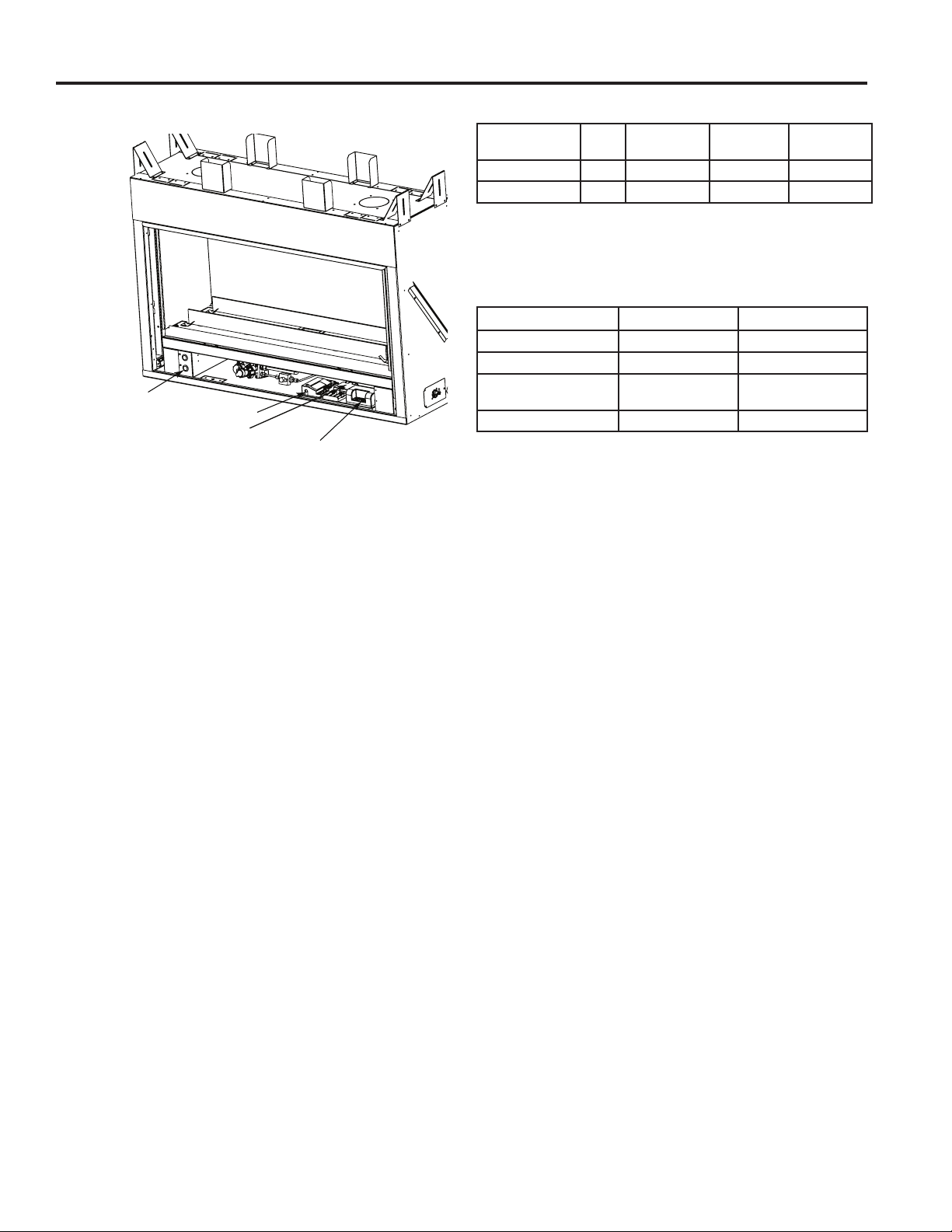
AVFLST42 CONTROLS
LED Switches
Control Module
Thermocouple Module
Aux Module
Figure 1. AVFLST42 Controls (Control Access Door Shown Open)
GAS SPECIFICATIONS & ORIFICE SIZE
MODEL FUEL
AVFLST42NIP NAT. 37,000 24,500 2.20 mm
AVFLST42PIP L P. 36,000 28,500 #55
MAX. INPUT
(BTU/h)
NOTE: For LP models an external regulator is required
to reduce supply pressure to a maximum of 13" w.c.
MIN. INPUT
(BTU/h)
ORIFICE
SIZE
GAS PRESSURES
NATURAL PROPANE (LP)
Inlet Minimum 5.0" w.c. 11.0" w.c.
Inlet Maximum 10.5" w.c. 13.0" w.c.
Regulator Pressure
Setting
Pilot Regulator 3.5" w.c. —
3.5" w.c. 10" w.c.
6
Monessen • AVFLST42 Installation Instructions • 4118-900 Rev. B • 05/2020
Page 7

AVFLST Vent Free Fireplace
33 ½" *
[851mm]
32"
[813mm]
Minimum
Rough
Framing
Height
37½"
[953mm]
39¾"
[1010mm]
43"
[1092mm]
FIREPLACE AND FRAMING DIMENSIONS
15⁄"
[386mm]
6⁄"
[154mm]
28"
[711mm]
13⁄"
[333mm]
*NOTE: The AVFLST42 unit must be raised at least 1.5 inches above the top surface of the nished oor when
using the AVFL42WFBT-A or AVFL42WCSS-A wide contemporary face.
32"
[813mm]
Figure 2. Fireplace dimensions
Interior wall
installation
Wall cover
thickness
Exterior wall
installation
Wall cover
thickness
½"[13mm]
⁄"[16mm]
½"[13mm]
or
⁄"[16mm]
Minimum rough
or
Minimum Rough
Framing Width
44"
[1118mm]
44"
[1118mm]
opening depth
for 5/8" wall thickness
12"
[305mm]
Minimum rough
opening depth
for 5/8" wall thickness
14⁄"
[378mm]
Figure 3. Framing dimensions with outdoor kit installed (AVFLSTSSODK)
Monessen • AVFLST42 Installation Instructions • 4118-900 Rev. B • 05/2020
48½"
[1232mm]
7
Page 8
PRE-INSTALLATION INFORMATION
AVFLST Vent Free Fireplace
GETTING STARTED
Check to verify that all listed parts have been received.
You should have the following:
• One (1) Unvented replace
• Two (2) Anchoring screws
• One (1)Installation/operating instructions
• Two (2) 5" noncombustible board
• Two (2) 2" x 32" deector glass
• Two (2) Bags reglass
• One (1) 90 watt bulb
• One (1) RC300 remote control
Carefully inspect the contents for shipping damage. If any
parts are missing or damaged, immediately inform the
dealer from whom you purchased the appliance. Do not
attempt to install any part of the appliance unless you
have all parts in good condition.
WHAT YOU WILL NEED FOR INSTALLATION
You must have the following items available before proceeding with installation:
• External regulator (for propane/LPG only)
• Manual shuto valve
• Piping which complies with local codes
• Sediment trap
• Phillips head screwdriver
• Tee joint.
• Pipe sealant approved for use with propane/LPG
(Resistant to sulfur compounds)
• Pipe wrench
WARNING!
Do not install the heater:
• Where curtains, furniture, clothing, or
other ammable objects are less than 36"
from the front of the heater.
• In high trac areas.
• In windy or drafty areas.
PLANNING THE INSTALLATION
In planning the installation for the replace it is necessary
to determine where the unit is to be installed and whether
optional accessories are desired. Gas supply piping should
also be planned. The following steps represent the normal
sequence of installation. Each installation is unique, however, and might require a dierent sequence.
1. Position fireplace in desired location. Refer to the
Fireplace and Framing Dimensions (page 7, Figures 2
and 3,) Fireplace Location (page 9, Figure 5) and
Clearances and Height Requirements (page 10, Figures
6 and 7.)
NOTE: Be sure all cardboard packing material has been
removed from under the unit.
2. Install following the instructions found in this manual.
3. Field wire main power supply to junction box. Refer to
the Electrical Installation section (page 15). (Electrical
connections should only be performed by an experienced, licensed certied service person).
4. Plumb gas line. Refer to the Connect the Gas (page
13, Figure 10) section found in this manual. (Gas
connections should only be performed by an experienced, licensed/certied service person).
5. Complete nish wall material and/or surround.
ADEQUATE COMBUSTION AND
VENTILATION AIR
This heater shall not be installed in a conned space or
unusually tight construction unless provisions are provided
for adequate combustion and ventilation air.
The National Fuel Gas Code, (ANSI Z223.1/NFPA54),
denes a conned space as a space whose volume is less
than 50 cubic feet per 1,000 BTU per hour (4.8m3 per kw)
of the aggregate input rating of all appliances installed in
that space, and an unconned space as a space whose
volume is not less than 50 cubic feet per 1,000 BTU per
hour (4.8 m3 per kw) of the aggregate input rating of all
appliances installed in that space. Rooms communicating
directly with the space in which the appliances are installed,
through openings not furnished with doors, are considered
a part of a conned space.
Unusually tight construction is dened as construction
where:
a. Walls and ceilings exposed to the outside atmosphere
have a continuous water vapor retarder with a rating of
1 perm (6 x 10
gasketed or sealed, and
b. Weather stripping has been added on openable win-
dows and doors, and
11
kg per pa/sec-m2) or less with openings
8
Monessen • AVFLST42 Installation Instructions • 4118-900 Rev. B • 05/2020
Page 9
AVFLST Vent Free Fireplace
Indoor application
Exterior wall application
with AVFLSTSSODK installed
PRE-INSTALLATION INFORMATION
c. Caulking or sealants are applied to areas such as joints
around window and door frames, between sole plates
and oors, between wall-ceiling joints, between wall
panels, at penetrations for plumbing, electrical and gas
lines and other openings.
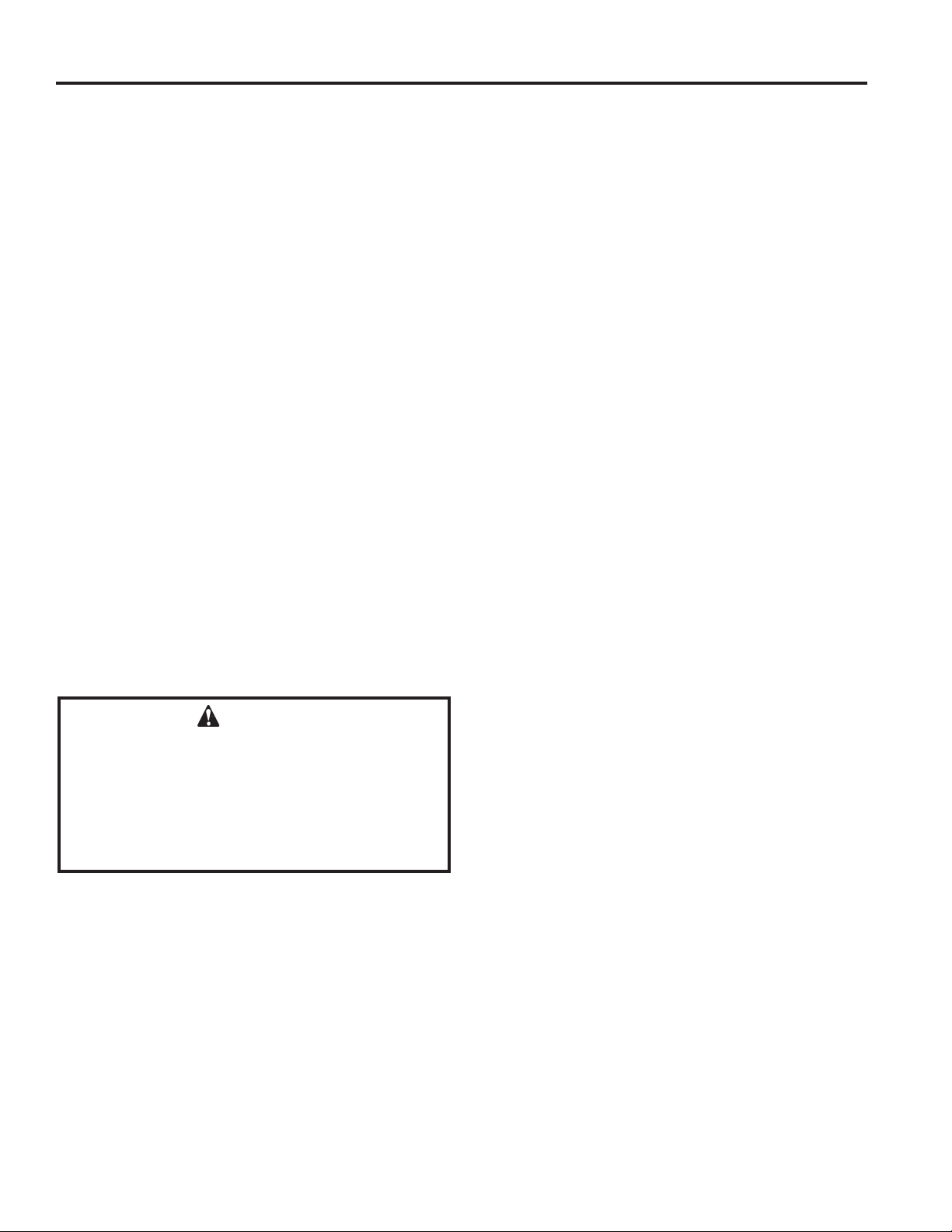
The following formula can be used to determine the maximum heater rating per the denition of unconned space:
BTU/Hr = (L1 + L2) Ft x (W) Ft x (H) Ft
50
Consider two connecting rooms with an open area
between, with the following dimensions:
L1 = 151/2 Ft., L2 = 12 Ft., W = 12 Ft., H = 8 Ft.
BTU/Hr = (151/2 + 12) x (12) x (8)
50
If there were a door between the two rooms the calculation
would be based only on the room with the heater.
BTU/Hr = (151/2) x (12) x (8)
50
Counter
Fireplace
H
W
FIREPLACE LOCATION
This unvented replace requires no outside venting and
burns cleanly and eciency. As a zero-clearance unvented
replace, it can be installed recessed into any wall that is
accessible to a gas line, except in a bedroom or bathroom.
Carefully select the best location for installation of your
unvented replace. The following factors should be taken
into consideration.
• Clearance to side wall, ceiling, woodwork and window
or other combustibles. Refer to Clearance and Height
Requirements section on Page 10. Minimum clearances to combustibles must be maintained.
• Location must not be aected by drafts caused by
kitchen exhaust fans, ceiling fans, return air registers
for forced air furnaces / air conditioners, windows or
doors.
• Installation must provide adequate ventilation and
combustion air.
• DO NOT INSTALL THIS MODEL IN A BEDROOM
OR BATHROOM.
• Location should be out of high trac areas and
away from furniture and draperies due to heat from
rebox.
• Never obstruct the front opening of the unvented re-
place or restrict the ow of combustion and ventilation
air.
• Minimize modications to existing construction. Refer
to Figure 5 below for location suggestions.
• Do not install in the vicinity where gasoline or other
ammable liquids may be stored. The unvented rebox must be kept clear and free from the combustible
materials.
Figure 4.
WARNING!
If the area in which the heater may be operated
does not meet the required volume for indoor
combustion air, combustion and ventilation
air shall be provided by one of the methods
described in the National Fuel Gas Code, ANSI
Z223.1/NFPA 54, the International Fuel Gas
Code or applicable local codes.
Monessen • AVFLST42 Installation Instructions • 4118-900 Rev. B • 05/2020
Figure 5. Possible Fireplace Locations
FP3029
9
Page 10
PRE-INSTALLATION INFORMATION
AVFLST Vent Free Fireplace
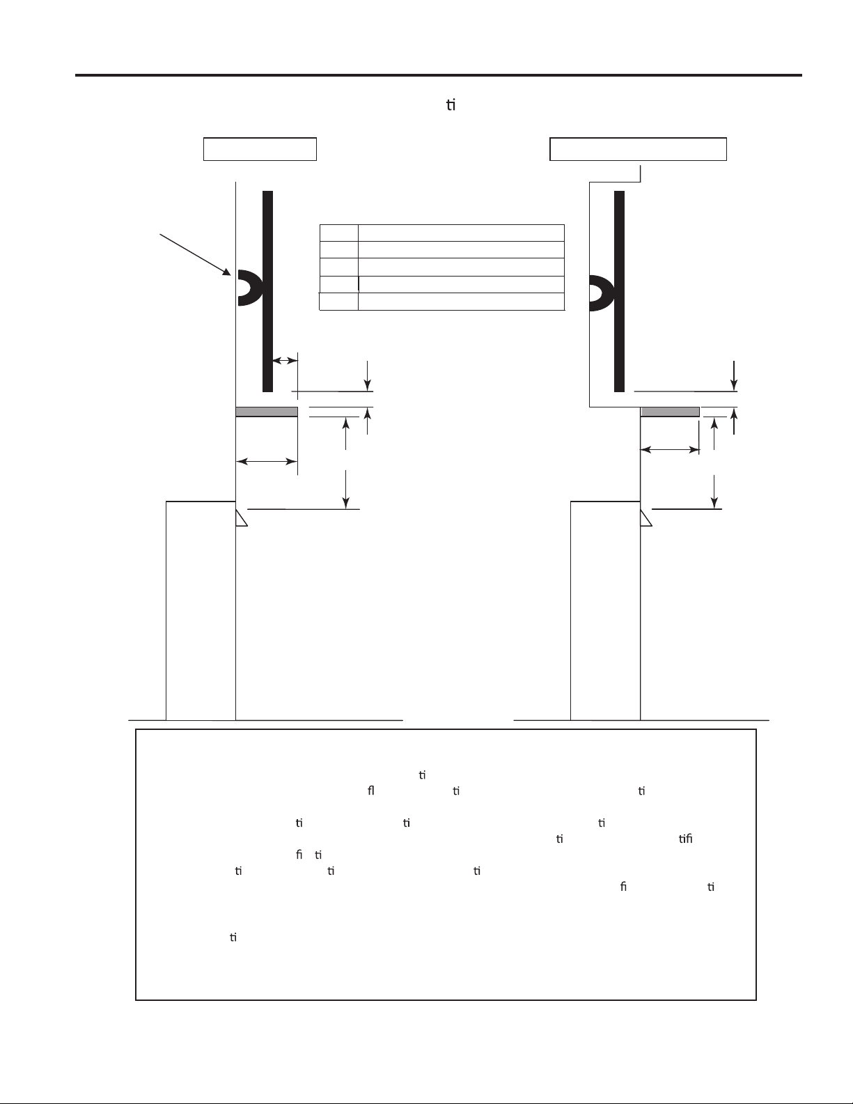
CLEARANCES AND HEIGHT
REQUIREMENTS
Ensure that minimum clearances shown in Figures 6 and
7 are maintained. Left and right clearances are determined
when facing the front of the rebox.
Follow these instructions carefully to ensure safe installation. Failure to follow these requirements may create a
re hazard.
Sidewall Clearances — The clearance from the inside of
the appliance to any combustible adjacent wall should not
be less than 6". Figure 6
Ceiling Clearance — The ceiling must be at least 36" from
the rebox opening. Figure 6
WARNING!
The dimensions shown in Figures 6 and 7
are minimum clearances to maintain when
installing this heater. Left and right clearances
are determined when facing the front of the
heater.
Follow these instructions carefully to ensure
safe installation. Failure to follow instructions
exactly can create a re hazard.
Floor Clearance — The replace may be installed directly
on a combustible oor or a raised platform of an appropriate
height. Do not place replace on carpeting, vinyl, tile or
other soft oor coverings. It may, however, be placed on at
wood, plywood, particle board or other hard surfaces. Be
sure replace rests on a solid continuous oor or platform
with appropriate framing for support so that no cold air can
enter from under the rebox. See note below regarding
oor installation with wide contemporary faces.
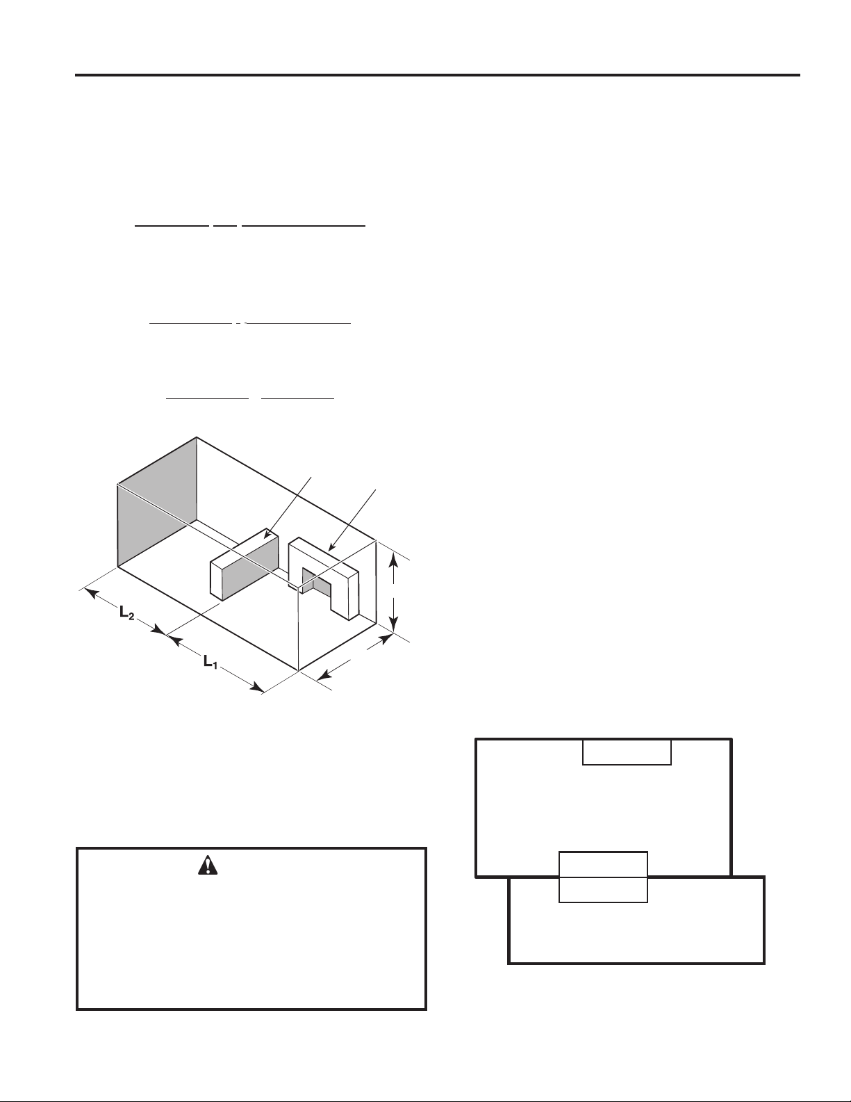
Mantel clearances — Must meet the clearance requirements detailed in Figures 6 and 7.
Wall
Stud
Mantel Clearances shown apply to both sides
of the See Through Unit.
36" Minimum
From Opening
12
" Max.
Depth
" Min.
6
1
2
/2" Max
Depth
28
" Min.
From Opening
18
" Min.
From Opening
FP3006
28"
Top of Fireplace
Opening
SIDE VIEW
Fireplace
Opening
TOP VIEW
12"
23"
6"
18"
1"
2¹⁄₂"
3"
Insulation
Board
Stando
1
2
/2"
FP3007
1¹⁄₂"
3¹⁄₂"
4¹⁄₂"
45°
5"
6"
FP3008
Figure 6. Sidewall and Ceiling Clearances
10
Monessen • AVFLST42 Installation Instructions • 4118-900 Rev. B • 05/2020
Figure 7. Mantel Clearances
Page 11
AVFLST Vent Free Fireplace
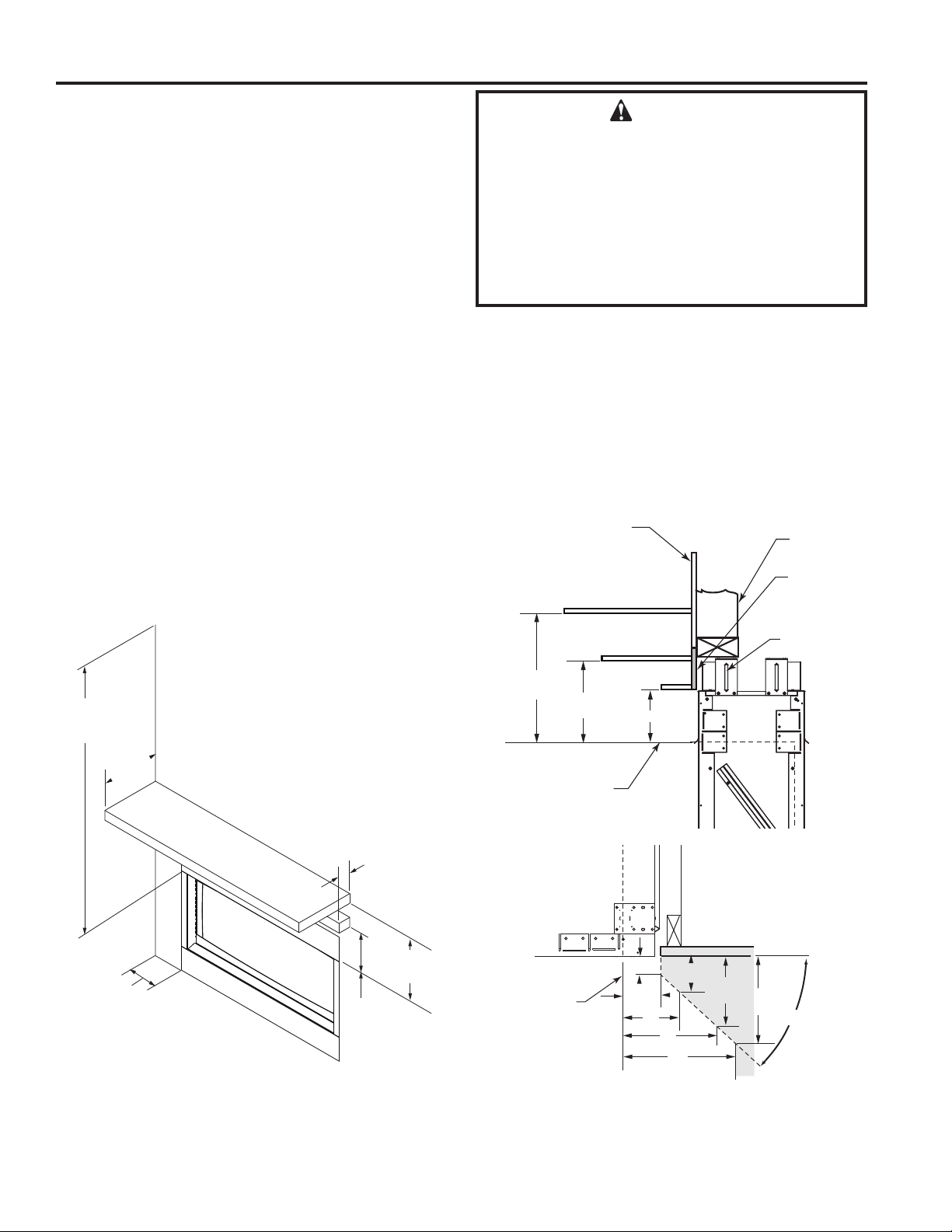
Good Faith Guidelines for TV Installa ons above a Typical Gas Fireplace
TV on the wall
PRE-INSTALLATION INFORMATION
TV recessed into the wall
TV Wall
Bracket
TV
A
Mantel
D
Mantel and TV Clearances shown apply to both
sides of the See Through Unit.
Item Minimum Dimensions
A 6 inches
4 inches
B
C 28 inches
D
12 inches
C
BB
D
C
Fireplace
Notes:
1. These are good faith recommended clearances only and not a guarantee of compliance with all TV
manufacturers’ maximum allowable opera
2. Since every home has unique air
can vary from manufacturer to manufacturer and from model to model, actual TV temperatures should
be validated at the
temperature exceeds the manufacturers’ maximum allowable opera
TV’s technical speci
informa
3. Mantel height and depth must conform to mantle requirements specified in the
manual.
on or have ques ons regarding the informa
me of each installa on. TVs should not be used in situa ons where the actual TV
ons. Contact the TV’s manufacturer directly if you cannot locate this
ca
ow characteris
ng temperatures.
cs and maximum allowable opera ng temperatures
on.
Fireplace
ng temperatures iden ed in the
replace installa
4. “C” dimension taken from the top of the hood or fireplace opening.
Sugges ons on how to further reduce TV temperatures:
5.
a. Increase “A” dimension.
b. Increase “C” dimension, however, increasing “B” dimension beyond maximum recommended
typically results in higher temperatures.
on
Monessen • AVFLST42 Installation Instructions • 4118-900 Rev. B • 05/2020
11
Page 12
FIREPLACE INSTALLATION
44"
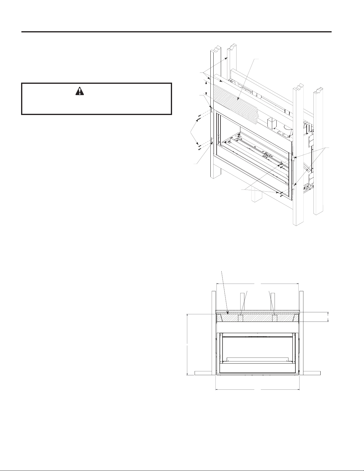
SECURE FIREPLACE TO FRAMING
AVFLST Vent Free Fireplace
The replace must be secured to the framing studs as
shown in Figure 8. Use eight (8) screws to attach replace
to framing. The side nailing anges are 1⁄2" or 5⁄8" to accommodate dierent wall thickness.
WARNING!
Never install combustible materials over front
face of replace.
FINISHING MATERIAL
NOTE: Any remote wiring (i.e. remote control, wall
switch), must be done prior to nal nishing to avoid costly
reconstruction.
Only noncombustible materials (i.e. brick, tile, slate, steel,
or other materials with a UL re rating of Zero) may be
used to cover the black painted face of the appliance. It is
permissible to bring combustible wall board to the top of
the standos on the top and to the wall board stand-os
on the sides of the unit. A 300°F minimum adhesive may
be used to attach facing materials to the black surface. If
joints between the nished wall and the replace surround
are sealed, a 300°F minimum sealant material (General
Electric RTV103 or equivalent) must be used.
NOTE: Fireplace may be installed on top of framing or
platform constructed of combustible materials which do
not protrude beyond the face.
Noncombustible Material
Framing
Members
Nailing
Flange
Screws
Nailing
Flange
Figure 8. Secure Fireplace to Framing Studs
5”
Screws
Nailing
Flange
NONCOMBUSTIBLE FACING INSTALLATION
CAUTION: The noncombustible wall board supplied with
this unit can be damaged if dropped or struck. Handle
with care.
1. Using drywall screws, secure the noncombustible board
to the two brackets on top of the unit. IMPORTANT: To
avoid cracking the board, pre-drill holes prior to securing
to the unit/framing.
2. Wipe any debris or dust from the noncombustible board
and drywall.
3. It is highly recommended to prime the facing using a
quality primer prior to taping and mudding. This will
ensure proper adhesion of both the tape and mud. The
supplied board is very porous.
4. Tape the seams using a mesh type tape.
5. Mud seams as normal. We recommend using a product
called Durabond high strength compound for the rst
coat. This product can be purchased at any hardware
store. Follow manufacturer's recommendations for curing
the mud. NOTE: Depending upon the nal nishing
method, use a minimum rated 300 degree sealant, drywall compound or thin set to seal the side and top joints.
6. Prime wall for a second time for proper adhesion of paint.
Supplied noncombustible board
43"
MOUNTING POINTS
32"
Figure 9. Noncombustible board installation
5"
12
Monessen • AVFLST42 Installation Instructions • 4118-900 Rev. B • 05/2020
Page 13

AVFLST Vent Free Fireplace
CONNECT THE GAS
NOTICE: A qualied gas appliance installer must connect
the heater to the gas supply. Consult all local codes.
►
Note: Gas line may be installed on the left or right side of
the appliance.
WARNING!
This appliance is equipped for either natural or propane
gas. Field conversion is not permitted.
WARNING!
Use new black iron or steel pipe. Internally
tinned copper or copper tubing can be used
per National Fuel Code, section 2.6.3, providing
gas meets hydrogen sulde limits, and where
permitted by local codes. Gas piping system
must be sized to provide minimum inlet
pressure (Listed on Data Plate) at the maximum
ow rate (BTU/hr). Undue pressure loss will
occur if the pipe is too small.
A manual shutoff valve must be installed
upstream of the appliance. Union tee and
plugged 1⁄8" NPT pressure tapping point should
be installed upstream of the appliance. Figure
10
A sediment trap should be installed upstream
to prevent moisture and contaminants from
passing through the pipe to appliance controls
and burners. Failure to do so could prevent the
appliance from operating reliably. Figure 10
FIREPLACE INSTALLATION
WARNING!
CHECK GAS TYPE: The gas supply must be the
same as stated on the heater’s rating plate. If the
gas supply is dierent, DO NOT INSTALL THE
HEATER. Contact your dealer for the correct
model.
IMPORTANT: Loosen the pipe adapter on the ex tube
before installing to the system piping.
Always use an external regulator for all propane/LPG heaters only, to reduce the supply tank pressure to a maximum
of 13" w.c. This is in addition to the internal regulator in the
heater valve.
When tightening the joint to the valve, hold the valve
securely to prevent movement.
Test all gas joints from the gas meter to the heater valve for
leaks using a gas analyzer or soap and water solution after
completing connection. DO NOT USE AN OPEN FLAME.
WARNING!
Connecting directly to an unregulated
propane/LP tank can cause an explosion.
WARNING!
DO NOT USE OPEN FLAME TO CHECK FOR
GAS LEAKS.
Figure 10. Gas Connection
Monessen • AVFLST42 Installation Instructions • 4118-900 Rev. B • 05/2020
To Fireplace
Stainless
Flexible Tube
Manual Shuto
Valve
Sediment
Trap
Pipe
Coupling
Pipe
Locations Pressure Tapping
Point Installation
Gas Supply Inlet
Tee Joint
3” Min.
Pipe Nipple
Cap
13
Page 14

FIREPLACE INSTALLATION
CHECK GAS PRESSURE
Figure 11
Check the gas pressure with the appliance burning and
the control set to HIGH.
The valve regulator controls the burner pressure which
should be checked at the pressure test point.
Open control access door at bottom front of unit to nd
valve and regulator.
Turn captured screw counterclockwise two or three turns
and then place tubing to pressure gauge over test point.
Use test point “A” closest to gas inlet. If the pressure is not
within the range listed for your gas type turn the valve regulator until it is within range. After taking pressure reading,
be sure and turn captured screw clockwise rmly to reseal.
Do not over torque. Check for gas leaks.
GAS PRESSURES
NATURAL PROPANE (LP)
Inlet Minimum 5.0" w.c. 11.0" w.c.
Inlet Maximum 10.5" w.c. 13.0" w.c.
Regulator Pressure
Setting
Pilot Regulator 3.5" w.c. —
3.5" w.c. 10" w.c.
AVFLST Vent Free Fireplace
TEST PORT 'A'
Figure 11. Pressure Test Point Location
14
Monessen • AVFLST42 Installation Instructions • 4118-900 Rev. B • 05/2020
Page 15
AVFLST Vent Free Fireplace
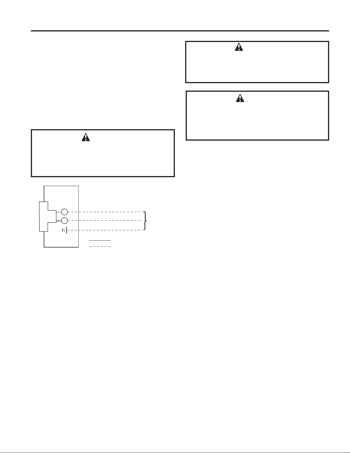
WIRING JUNCTION BOX
1. Before installing, wire the receptacle into an electrical
circuit. This should be done before framing the replace. Wire with minimum 60° C wire in accordance
with prevailing codes.
2. Remove the cover plate located on the outer shell-
►
right side.
3. Loosen two screws on the Romex connector, feed the
necessary length of wire through the connector and
tighten the screws.
4. Make all necessary wire connections and reattach the
cover plate to the outer shell.
WARNING!
Label all wires prior to disconnection when
servicing controls. Wiring errors can cause
improper and dangerous operation. Verify
proper operation after servicing.
ELECTRICAL INSTALLATION
WARNING!
Electrical connections should only be performed by
a qualied licensed electrician. Main power supply
must be turned o before connecting to the main
electrical power supply or performing service.
WARNING!
Electrical Grounding Instructions:
This appliance is equipped with a three-prong
(grounding) plug for your protection against shock
hazard and should be plugged directly into a
properly grounded three prong receptacle.
IMPORTANT: Always check local building codes. This installation must comply with local regulations as well as
the National Electric Code.
Junction Box
Figure 12. Junction Box Wiring Diagram
120V AC
60Hz
Factory Supplied
Not Supplied
Monessen • AVFLST42 Installation Instructions • 4118-900 Rev. B • 05/2020
15
Page 16

ELECTRICAL INSTALLATION
TO JUNCTION
AVFLST Vent Free Fireplace
Wiring Requirements
Intellire™ Plus ODS Ignition System Wiring
• Wire the appliance junction box to 110-120 VAC for
proper operation of the appliance.
WARNING! Risk of Shock or Explosion! DO NOT wire
IFP ODS controlled appliance junction box to a switched
circuit. Incorrect wiring will override IFP ODS safety lockout.
• Refer to Figure 13 and 14, IFP ODS Wiring Diagram.
• This appliance is equipped with an Intellire™ Plus
control valve which operates on a 6 volt/1.5 AMP system.
• Plug the 6 volt transformer plug into the appliance junction
box to supply power to the unit OR install 4 AA cell
batteries (not included) into the battery pack before use.
PILOT
THERMOCOUPLE MODULE
NOTICE: Batteries should only be used as a power source
in the event of an emergency power outage. Batteries
should not be used as a primary long-term power source.
Battery polarity must be correct when installing batteries.
When using batteries as a power source, the 6-volt
transformer must be unplugged from the receptacle.
Do not store batteries in the battery pack when the
appliance is powered by the 6 volt transformer connected
to permanent electrical service.
Accessories Requirements
• This appliance ships standard with a remote control.
Wiring for optional Hearth & Home Technologies approved
accessories should be done now to avoid reconstruction.
Follow instructions that come with those accessories.
THERMOCOUPLE
TO Y CORD
(120VAC) SEE
FIGURE 14 ON
NEXT PAGE
ORANGE
(PILOT)
Thermocouple Module Wire Assembly
6V DC
SUPPLY
CONTROL MODULE
FLAME
MODULATION
GREEN
(MAIN)
I
S
8K-1 Adapter Box Wire Assembly
RED
BLACK
BROWN
BROWN/RED
OPTIONAL ON/OFF
SWITCH
GROUND
THERMOCOUPLE
SENSOR
WHITE
BATTERY PACK
SENSOR
ORANGE
6V DC
ODS Adapter Box
ODS to Adapter Box Wire Assembly
AUX300 MODULE
AUX 1
FAN
AUX 2
TO TOP DOME
RC300 4.5V DC
(AAA X 3)
BOX 120VAC
LIGHT
Figure 13. IntelliFire™ Plus ODS Wiring Diagram
►
16
Monessen • AVFLST42 Installation Instructions • 4118-900 Rev. B • 05/2020
Page 17

AVFLST Vent Free Fireplace
6V DC Supply
(See Figure 13 on previous
page)
To Junction
Box 120VAC
Use Y cord supplied in install bag to plug in 6V
DC supply for control module and LED
transformer.
LED STRIP
LED STRIP
TRANSFORMER
TOP BUTTON
ON/HI/MED/LO/OFF
BLACK
BLACK
GREEN
RED
BOTTOM BUTTON
BLACK
Color Selection
BLACK
Figure 14. LED Wiring Diagram
Monessen • AVFLST42 Installation Instructions • 4118-900 Rev. B • 05/2020
CONTROL
MODULE
RED
GREEN
YELLOW
BLUE
17
Page 18

FINAL INSTALLATION
AVFLST Vent Free Fireplace
INSTALLATION OF AIR DEFLECTION
GLASS
NOTE: The 32" deector glass must be installed prior
to placing any reglass or stone media on the burner.
To install the air deection glass simply place the tabs
(located at the bottom of the glass) into the slots at
either end of the burner oor, in front of the burner ports.
The glass should stand upright, neither leaning forward
nor backward. Repeat for the second glass deector
installation.
FIREGLASS ONLY PLACEMENT
NOTE: Two (2) bags of reglass are supplied with the
replace. Both bags may be used to cover the entire oor
and burner. We advise against using additional reglass
as too much can cut o the proper amount of air the burner
needs to burn cleanly. This may cause sooting.
1. Spread reglass evenly in one layer over the entire oor
and burner. It is important to not have the reglass too
thick on ported area (single layer only).
2. Turn burner on and adjust reglass over ported areas
to achieve an even, clean ame.
GLASS AND OPTIONAL STONE KIT
PLACEMENT
1. For best results, spread reglass evenly over the entire
oor and burner making sure the reglass is not too
thick over the burner ports (single layer only).
2. Place the stones randomly in front of and behind the
air deection glass. CAUTION: Do not allow stones to
sit directly on burner or in ame. Figure 17.
3. Turn burner on and adjust reglass over the ported area
to achieve an even, clean ame. (page 28, Figure
22.)
Figure 15. Air Deection Glass Placement (before) Figure 16. Air Deection Glass Placement (after)
Burner Surface
Examples of
Stone Placement
Figure 17. Air Deection Glass and Stone Placement
18
Monessen • AVFLST42 Installation Instructions • 4118-900 Rev. B • 05/2020
Page 19

AVFLST Vent Free Fireplace
WARNI NG : If you do not follow these instructions exactly, a fi re or explosion may result causing property damage, personal injury or loss of life.
A. This appliance is equipped with an intermittent pilot ignition (IPI) device which
automatically lights the burner. DO NOT try to light the burner by hand.
B. BEFORE LIGHTING, smell all around the appliance area for gas. Be sure to smell
next to the fl oor because some gas is heavier than air and will settle on the fl oor.
WHAT TO DO IF YOU SMELL GAS
• DO NOT try to light any appliance.
• DO NOT touch any electric switch; do not use any phone in your building.
1. This appliance is equipped with an ignition device which automatically
lights the burner. DO NOT try to light the burner by hand.
GAS
VALVE
1. Equipped with wall switch: Turn ON/OFF switch to OFF.
Equipped with remote or wall control: Press OFF button.
Equipped with thermostat: Set temperature to lowest setting.
IPI LIGHTING INSTRUCTIONS
FOR YOUR SAFETY READ BEFORE LIGHTING
• Immediately call your gas supplier from a neighbor’s phone. Follow the gas supplier’s instructions.
• If you cannot reach your gas supplier, call the fi re department.
C. DO NOT use this appliance if any part has been under water. Immediately call
a qualifi ed service technician to inspect the appliance and to replace any part of
the control system and any gas control which has been under water.
LIGHTING INSTRUCTIONS (IPI)
2. Wait fi ve (5) minutes to clear out any gas. Then smell for gas, including near the
fl oor. If you smell gas, STOP! Follow “B” in the Safety Information located on the
top of this label. If you do not smell gas, go to next step.
3. To light the burner:
Equipped
Equipped with remote or wall control: Press ON or FLAME button.
4. If the appliance does not light after three tries, call your service technician or gas
TO TURN OFF GAS TO APPLIANCE
2. Service technician should turn off electric power to the control when performing
with wall switch: Turn ON/OFF switch to ON.
Equipped with thermostat: Set temperature to desired setting.
supplier.
service.
4604-200
WARNING:
DO NOT CONNECT LINE VOLTAGE (110/120 VAC OR 220/240 VAC) TO THE CONTROL VALVE.
Improper installation, adjustment, alteration, service or maintenance can cause
injury or property damage. Refer to the owner’s information manual provided with
this appliance. For assistance or additional information, consult a qualifi ed installer,
service agency or the gas supplier.
This appliance needs fresh air for safe operation and must be installed so there are
provisions for adequate combustion and ventilation air.
CAUTION:
Keep burner and control compartment clean. See installation and operating instructions accompanying appliance.
Hot while in operation. DO NOT touch. Keep children, clothing, furniture, gasoline
and other liquids having fl ammable vapors away.
NOT FOR USE WITH SOLID FUEL
follow the National Fuel Gas Code, ANSIZ223.1/ NFPA 54, or the National Gas and
Propane Installation code, CSA B149.1.
For additional information on operating your
Hearth & Home Technologies fi replace, please refer to www.fi replaces.com.
.
,enon fi ;yna fi ,sedoc lacol htiw ecnadrocca ni dellatsni eb tsum ecnailppa sihT
4604-201
Monessen • AVFLST42 Installation Instructions • 4118-900 Rev. B • 05/2020
19
Page 20

OPERATING INSTRUCTIONS
AVFLST Vent Free Fireplace
Initial Use
Initial Break-in Procedure
• The replace should run three to four hours continuously
on high.
• Turn the replace o and allow it to completely cool.
This cures the materials used to manufacture the replace.
• Some people may be sensitive to smoke and odors.
• Smoke detectors may activate.
Heat Management
Burn Rate
The Artisan model has a variable burn rate which is controlled by the remote control. Therefore the ame height
is adjustable.
The ame height may be adjusted as desired by locating
the ame option on the remote control and adjusting up or
down to desired ame height.
Operation During A Power Outage
The IntelliFire™ Plus ODS intermittent pilot ignition system
comes with a battery backup system that enables the
system to operate in a power outage. The system oers
seamless transition from household AC power to battery
backup. A factory-installed battery pack is located in the
control cavity of the appliance. See Figure 18. Battery
longevity and performance will be aected by long term
exposure to the service temperatures of this appliance.
• Remote receiver is integrated into the ignition module
• Use the remote to turn the appliance on.
• To preserve battery life, do not use the HI/LO ame or
THERMOSTAT options.
Ignition Module:
• Locate the ignition module in the control cavity.
• Slide the ON/REMOTE/OFF switch to the ON position.
NOTICE: Some functionality will be lost when using
battery backup including remote control, lights, or any
other auxiliary functions that require household 110-120
VAC power.
To Return to Operation Using Electrical (AC) Power
Standard Wall Switch or Factory-Installed ON/OFF
Switch:
• Toggle the switch to OFF.
• Remove the batteries from the battery tray.
Wireless Remote:
• Slide the ON/REMOTE/OFF switch to the REMOTE
position.
• Remove the batteries from the battery tray.
Ignition Module:
• Slide the ON/REMOTE/OFF switch to the REMOTE
position.
• Remove the batteries from the battery tray.
NOTICE: Batteries should only be used as a power source
in the event of an emergency power outage. Batteries
should not be used as a primary long-term power source.
To Operate Fireplace Using Battery Power (DC):
1. Access the control cavity of the appliance. See Figure 18
for location. Lift the barrier screen o of the appliance.
2. Locate the battery tray and insert four AA cell batteries.
See Figure 18. Battery polarity must be correct or
module damage will occur. A complete wiring diagram
is included in the electrical section of the appliance
installation manual.
3. Turn the appliance on according to the instructions
below for the appropriate type of control:
Standard Wall Switch or Factory-Installed ON/OFF
Switch:
• Toggle the switch as you would under normal
circumstances.
Wireless Remote:
20
Monessen • AVFLST42 Installation Instructions • 4118-900 Rev. B • 05/2020
Gas Valve
Control Module
Battery Tray
Figure 18. Control Cavity Location
Page 21

AVFLST Vent Free Fireplace
IntelliFire™ Plus ODS
Hearth & Home Technologies disclaims any responsibility
for, and the warranty will be voided by, the following actions:
• Installation and use of any damaged system component.
• Modication of the system component.
• Installation other than as instructed by Hearth & Home
Technologies.
• Installation and/or use of any component part not approved
by Hearth & Home Technologies.
Any such action may cause a re hazard.
• Read, understand and follow these instructions for safe
installation and operation.
Introduction
The RC300 multifunctional remote control is designed
to control light, ame height and interior dome lighting. The RC300 is equipped with thermostat functions
which can automatically control the temperature in the
room in which it is installed. The control is only for use
with the Hearth & Home Technologies IntelliFire Plus™
system (IPI). The AUX300 module is rated for 120 VAC,
60 Hz, and is required for operation of this remote control
device.
Installation Precautions
This remote control is tested and safe when installed in
accordance with this installation manual. Do not install
any components that may be damaged.
Do not modify, disassemble, or substitute any of the components included with this kit. Installation of this unit must
be done by a qualied service technician.
Placement of this remote control may aect performance.
An assessment of the space should be done prior to installation for optimum performance.
Determine Location
Determine the location for the remote control. The selected
location should be in the same space as the gas replace.
Never place this unit in a separate room. The remote control
must be placed within 30 feet (9.14 m) of the replace but
should not be exposed to extreme heat.
The RC300 is approved for interior installation and should
not be used in exterior applications.
• Keep remote control out of reach of children.
FCC Requirements
Warning! Risk of Fire! Changes or modication to
this unit not expressly approved by the party responsible
for compliance could void the user's authority to operate
the equipment.
Note: This equipment has been tested and found to
comply with the limits for a Class B digital device, pursuant to Part 15 of the FCC Rules. These limits are
designed to provide reasonable protection against
harmful interference in a residential installation. This
equipment generates, uses, and can radiate radio
frequency energy and, if not installed and used in accordance with the instructions, may cause harmful interference to radio communications. However, there is
no guarantee that interference will not occur in a particular installation. If this equipment does cause harmful
interference to radio or television reception, which can
be determined by turning the equipment o and on, the
user is encouraged to try to correct the interference by
one or more of the following measures:
• Reorient or relocate the receiving antenna.
• Increase the separation between the equipment and
receiver.
• Connect the equipment into an outlet on a circuit
dierent from that to which the receiver is connected.
• Contact the dealer or an experienced radio TV technician for help.
Changing Temperature Scale
To change the temperature display between Celsius and
Fahrenheit, remove the battery cover from the back of the
remote control and slide the switch to your desired temperature scale (see Figure 1). The screen will automatically change the indicators on the room temperature and
set temperature portion.
Figure 1. Temperature scale
Monessen • AVFLST42 Installation Instructions • 4118-900 Rev. B • 05/2020
21
Page 22

IntelliFire™ Plus ODS
Installation of Remote Control Housing
Caution! Risk of Fire! DO NOT install damaged or mod-
ied components. Warranty will be voided if damaged or
modied components are installed.
Kit components: One remote control, two #6 screws, two
wall anchors, 3 AAA batteries and one AUX300 module. If
batteries are properly installed the remote will turn on
1. Remove remote control components from packaging.
2. Remove battery cover from the back of the remote by
sliding it down and install 3 AAA batteries.
To prevent unintended operation when not using your replace for an extended period of time (summer months,
vacation, trips, etc):
• Remove batteries from remote control.
• Unplug switching adapter and remove back-up batteries.
3. Secure the remote control housing on a at wall surface using the two screws and wall anchors provided.
See Figure 2.
AVFLST Vent Free Fireplace
Figure 3. Remote in Housing
5. Close the housing door. See Figure 4.
Figure 2. Mounting Remote Control Housing
4. Place remote control inside housing. See Figure 3.
22
Monessen • AVFLST42 Installation Instructions • 4118-900 Rev. B • 05/2020
Figure 4. Mounting Remote Control Housingng
Page 23

AVFLST Vent Free Fireplace
Programming the RC300 to the Control Module
Caution! Risk of burns! DO NOT program the
remote control to the control module when replace
is hot.
• Verify the ON/OFF/REMOTE switch is in the REMOTE
position. Green LED light will blink three times and wall
switch will beep once 5 seconds later when ready. See
Figure 5.
• Using a small item (such as a paper clip) press and
release the LEARN button located near the ON/OFF/
REMOTE switch. See Figure 5.
• Control module will beep once and LED will blink green
for 10 seconds.
• While the LED is blinking, press the POWER button on
the remote control. A double beep will come out of the
control module to indicate that it has been programmed
successfully.
NOTICE: Up to three remote controls can be programmed
into the control module. Simply press a button on the other
remote controls during the 10 second programming process
to add another remote into the system. It is recommended
to program only one RC300 remote control.
To clear memory in the control module, use a small item
(such as a paper clip) to press and release the LEARN
button. Control module will beep once and LED will blink
green for 10 seconds DO NOT press any buttons on the
remote during the ten seconds that the green LED blinks.
The memory will be cleared. Note that the RC300 will not
be programmed if it’s in STANDBY mode. Press the ON/
OFF button twice to switch to IDLE mode.
IntelliFire™ Plus ODS
REMOTE POSITION
Figure 5. Programming RC300 (Control Module is located under
unit.)
Monessen • AVFLST42 Installation Instructions • 4118-900 Rev. B • 05/2020
23
Page 24
IntelliFire™ Plus ODS
V
Menu
V
V
V
AVFLST Vent Free Fireplace
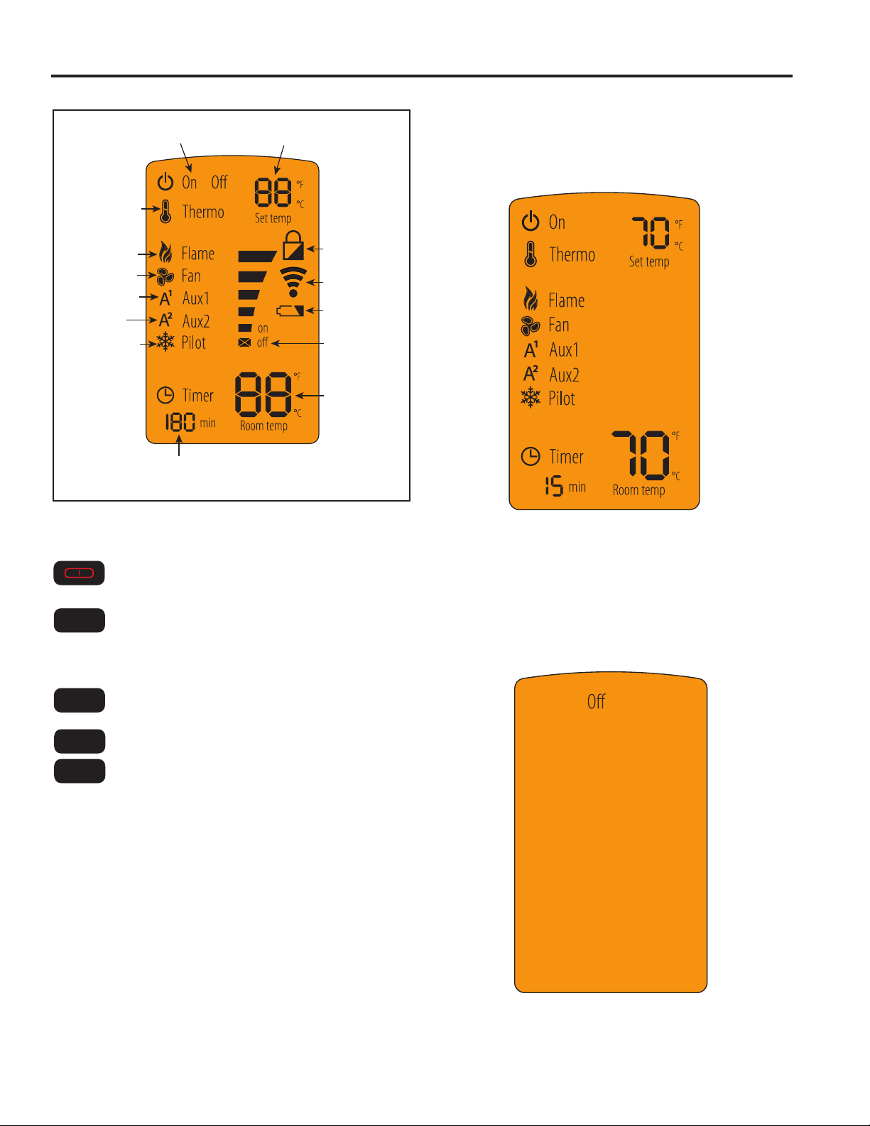
Display Screen
FIREPLACE STATUS
THERMOSTAT
FLAME HEIGHT
FAN SPEED
ADJUSTABLE
AUXILIARY
ADJUSTABLE
OUTPUT (ON/OFF)
CONSTANT PILOT
TIMER DISPLAY/FUNCTION
Figure 8. RC300 Display Screen
THERMOSTAT DESIRED
TEMP SETTING
CHILD LOCK
INDICATOR
TRANSMISSION
INDICATOR
LOW BATTERY
INDICATOR
FUNCTION LEVEL
INDICATOR
ROOM TEMP
DISPLAY
Idle When Remote is in ON Mode
The remote control will go into an idle mode if no buttons
are pressed within 5 seconds. Press any button to resume full functionality. In idle mode, only active functions
will show on the screen.
Function Buttons
Use POWER button to turn the unit on and o.
Menu
Use MENU button to display the menu functions.
Only functions that can be activated will be
displayed. For example: Flame Height will not
be displayed when the remote status is OFF.
Select
Use the SELECT button to select the current
feature.
V
Use the UP and DOWN arrows to toggle
through the menu functions and value selec-
V
tions in the submenus.
Figure 9. RC300 Idle Mode
Standby mode
The remote control will go into a standby mode if no buttons are pressed within 5 minutes. Press the POWER
button to reactivate the remote control to ON mode. Active functions will be displayed
24
Figure 10. RC300 Standby Mode
Monessen • AVFLST42 Installation Instructions • 4118-900 Rev. B • 05/2020
Page 25

AVFLST Vent Free Fireplace
IntelliFire™ Plus ODS
About ON Mode
• All functions can be accessed when the remote control
is in the ON mode.
• Only active functions will be displayed when the remote
control is in the ON mode.
About OFF Mode
Only the following functions can be accessed in the OFF
mode:
• AUX1
• AUX2-Top Dome Light
Only active functions will be displayed when the remote
control is in the OFF mode.
Turning On the Fireplace
• Press the POWER button to turn the replace ON. The
replace will rst ignite the pilot. Once the pilot ame is
established the main burner will be lit.
NOTICE: Whenever the replace is cycled from OFF to
ON, the main burner will light on high for 10 seconds before
returning to the previous user setting.
Adjusting Flame Height
• Press the MENU button to activate the menu.
• Using the UP and DOWN arrows highlight the FLAME
icon and press SELECT.
• Use the UP and DOWN arrows to adjust the FLAME
HEIGHT, then press SELECT. The FLAME HEIGHT
can be adjusted to 5 dierent settings.
NOTICE: FLAME HEIGHT will not be adjustable for rst
ten seconds when replace is turned on.
NOTICE: The system will remember the previous FLAME
HEIGHT setting and will automatically adjust after 10
seconds.
Adjusting Thermostat
• Press the MENU button to activate the menu.
• Using the UP and DOWN arrows highlight the THERMO
icon and press SELECT.
• Use the UP and DOWN arrows to turn the THERMO ON
or OFF, then press SELECT (the SET TEMP will start
blinking). Using the UP and DOWN arrows select the
desired temperature and press SELECT.
NOTICE: If the THERMO function is on, the SET TEMP
can be adjusted at any time by pressing the UP and DOWN
arrows.
NOTICE: As the ROOM TEMP (RT) approaches SET
TEMP (ST), the remote system will automatically adjust
the ame height. If the RT rises above ST, the replace
will shut down the main burner. After this, the replace will
turn back on after the RT drops below the ST.
NOTICE: The system requires a two degree Fahrenheit
or higher temperature dierence between RT and ST for
the replace to turn on.
NOTICE: The system will remember the previous TEMPERATURE setting when THERMOSTAT mode is cycled
ON or OFF.
NOTICE: If your installation includes an optional wired
ON/OFF wall switch, it should be in the OFF position when
using the RC300 in thermostat mode.
Adjusting Timer
• Press the MENU button to activate the menu.
• Using the UP and DOWN arrows highlight the TIMER
icon and press SELECT.
• Use the UP and DOWN arrows to turn the TIMER ON
or OFF, then press SELECT. Using the UP and DOWN
arrows select the desired set time and press SELECT.
Timer operates in increments of 15, 30, 45, 60, 90, 120
and 180 minutes.
NOTICE: Some models use xed valves, which cannot
be adjusted.
AUX2 Function (Top Dome Light)
• Press the MENU button to activate the menu.
• Using the UP and DOWN arrows highlight the AUX1 icon
and press SELECT.
• Use the UP and DOWN arrows to adjust the AUX1 output,
then press SELECT. The AUX1 function can be adjusted
to 4 dierent settings: HI, MED, LOW and OFF.
Monessen • AVFLST42 Installation Instructions • 4118-900 Rev. B • 05/2020
Setting the Child Lock
• Press and hold the MENU and UP arrow buttons simul-
taneously for 4 seconds to enable or disable the child
lock feature.
NOTICE: No functions will be usable until child lock feature
is disabled.
25
Page 26

IntelliFire™ Plus ODS
Power Outage
• If replace battery backup system IS installed at time of
power outage, replace operation will not be interrupted.
• If replace battery backup system IS NOT installed at
time of power outage, replace will shut o. To resume
replace operation, install battery backup.
NOTICE: Battery polarity must be correct or module
damage will occur.
Manual Fireplace Shuto
In the unlikely event that the remote wall switch malfunctions and will not turn o the replace, call your dealer
for service assistance. In the meantime, you may choose
one of the following actions to turn o the replace:
CAUTION! Risk of burns! Fireplace surfaces are hot
when operating and during cool down. Use care and wear
gloves when opening the front and accessing components inside the replace.
Check remote screen for battery level indicator, replace
the batteries if low battery is indicated (See Figure 8,
page 24).
The replace may be manually shut down by one of the
following methods:
Turn o the control module:
• Open or remove the decorative front to access the control
module.
• Move switch to OFF (See Figure19, page 27).
Disconnect power to the control module:
• Open or remove the decorative front to access power
cord to the junction box and/or back-up batteries.
• Unplug the control module and/or remove back-up
batteries.
Shut o gas to the control:
• Open or remove the decorative front and locate the gas
shut-o valve to the left of the gas control.
• Rotate the valve 90 degrees to turn o gas supply.
Turn o power to the replace (if back-up batteries are
not installed):
• Unplug unit from electrical source, if you cannot unplug
then:
• Locate house circuit breaker for replace.
• Turn o the circuit breaker.
AVFLST Vent Free Fireplace
26
Monessen • AVFLST42 Installation Instructions • 4118-900 Rev. B • 05/2020
Page 27

AVFLST Vent Free Fireplace
IntelliFire™ Plus ODS
Detailed Component Operating Instructions— Intellire™ Plus ODS
Control Module Operation
1. The control module has an ON/OFF/REMOTE selector
switch that must be set. See Figure 19.
OFF Position: Appliance will ignore all power inputs and
will not respond to any commands from a wall switch or
remote. The unit should be in the OFF position during
installation, service, battery installation, fuel conversion,
and in the event that the control goes into LOCK-OUT
mode as a result of an error code.
ON Position: Appliance will ignite and run continuously
in the HI ame setting, with no adjustment in ame
output. This mode of operation is primarily used for
initial installation or power outage operation with battery
backup.
REMOTE Position: Appliance will initiate commands
from an optional wired wall switch and/or the wireless
remote (RC300).
2. If using a wired wall switch with the module in REMOTE
mode, the ame output can be adjusted with the HI/LO
selector switch on the module. See Figure 19. Note
that the ame HI/LO selector switch will become inactive
once a remote control (RC300) is programmed to the
control module. Note that the control module will always
ignite the replace on HI and remain so for the initial 10
seconds of operation. If the HI/LO is switched to the
LO position, the ame output will automatically drop to
the lowest setting after the ame has been established
for 10 sec. After this 10 second period, the ame can
be adjusted from HI to LO with the switch.
3. The control module has safety feature that automatically
shuts down the replace after 9 hours of continuous
operation without receiving a command from the RC300
remote.
4. If you intend to use both an optional wired wall switch
and the RC300 remote control to operate your replace,
the wall switch will override any commands given by
the remote.
5. Module Reset
This module may lock-out under certain conditions.
When this occurs, the appliance will not ignite or
respond to commands. The module will go into
lock-out mode by emitting three audible beeps, then
continuously displaying a RED/GREEN error code at
its status indicator LED.
• Check battery tray. Remove batteries if installed.
Batteries should only be installed for use during power
outages.
• Locate the module selector switch. (See Figure 19).
MODULE
SELECTOR
SWITCH
FLAME HI/LOW
SWITCH
Figure 19. Control Module
STATUS
INDICATOR LED
NG/LP GAS-TYPE
SELECTOR SWITCH
• Set the module selector switch to the OFF position.
• Wait ve (5) minutes to allow possible accumulated gas
to clear.
• Set the module selector switch to ON or REMOTE
position.
• Start the appliance.
WARNING! Risk of Explosion! DO NOT press the
module reset switch more than one time within a ve
minute time period. Gas could accumulate in rebox. Call
a qualied service technician.
Nine Hour Safety Shutdown Feature
The appliance has a safety feature that automatically
shuts down the replace after nine hours of continuous
operation without receiving a command from the wall
switch or optional remote.
Appliance ON/OFF
Use the IntelliFire™ Plus Remote Control to control the ON/
OFF function of the appliance. Follow instructions included
with the remote control. If desired, a wall switch may be
installed to control the ON/OFF function of the appliance.
Monessen • AVFLST42 Installation Instructions • 4118-900 Rev. B • 05/2020
27
Page 28

FLAME APPEARANCE & LED CONTROL
FLAME APPEARANCE
Flames from the pilot, front and rear burner should be
visually checked as soon as the heater is installed.
In addition, periodically check the ames visually during
operation.
CHECK THE PILOT FLAME
The pilot ame must always be present when the
heater is in operation. It should just touch the top of the
thermocouple tip for natural gas. Refer to Figure 20 for
correct pilot ame.
If the pilot ame does not touch the thermocouple, then
the main burner cannot function reliably. Refer to Figure
21 for incorrect shape of pilot ame.
AVFLST Vent Free Fireplace
Figure 22. AVFLST42 Burner Flame Appearance
(Shown with reglass only)
CHECK THE BURNER FLAME
In normal operation, at full rate after 15 minutes, the ames
should appear as shown in Figure 22.
Thermocouple
for Natural Gas
Figure 20. Correct ODS Pilot Flame Appearance
Thermocouple
for Natural Gas
Thermocouple
for LP
Thermocouple
for LP
LED CONTROL
– Multi-colored LED lights — Two buttons turn LEDs
On (Hi/Med/Lo) and Off and cycles through the color
selection.
– Color selection options — Using the color selection
button, you can choose from ten (10) dierent lighting
options.
1. Color fade – This selection will cycle through the range
of colors listed below.
2. Color fade (slow) – This selection is the same as the
previous selection; only at a slower rate.
3. Pause color – This selection will allow the user to
choose a custom color through the hues of colors of
the slow fade.
• Blue
• Violet
• Red
• Yellow
• Green
• Cyan
• White
4. Pushing the color selection button again cycles back
to the rst color fade selection.
Figure 21. Incorrect Pilot Flame Appearance
28
Monessen • AVFLST42 Installation Instructions • 4118-900 Rev. B • 05/2020
ON (Hi/Med/Lo)
O button
Screws
Figure 23. LED Controls
Color selection
button
Page 29

AVFLST Vent Free Fireplace
MAINTENANCE AND CLEANING
CLEANING AND SERVICING
Annual inspection and cleaning by your dealer or qualied service technician is recommended to prevent
malfunction and/or sooting.
WARNING!
Turn off heater and allow to cool before
cleaning. Disconnect electrical power before
cleaning or servicing.
Remove reglass and/or stones as applicable.
PERIODIC CLEANING – Refer to parts diagram for
location of items discussed below.
• Do not use cleaning uid to clean any part of heater.
• Brush stones with soft bristle brush or vacuum with
brush attachment.
• Remove glass media and rinse with clean water.
Spread media out on paper towel or equivalent and
allow to dry completely.
• Vacuum loose particles and dust from the burner,
controls.
• Inspect and clean burner air intake holes. Remove
lint or particles with vacuum, brush, or pipe cleaners.
Failure to keep air intake holes clean will result
in sooting and poor combustion.
• The replace face should be dusted and wiped with
a wet soapy cloth.
Top light
Figure 24. Top Light Position; Porcelain Panel Screw Location
REPLACING TOP LIGHT BULB
TOP LIGHT BULB INSTALLATION
1. Remove three screws holding light cover in place
(as shown in Figure 25.)
2. Insert (1) 90W bulb provided into socket.
3. Replace top light cover with three screws.
Light cover
screws
ANNUAL CLEANING/INSPECTION – Refer to parts
diagram for location of items discussed below.
• Inspect and clean burner air intake holes. Remove
lint or particles with vacuum, brush or pipe cleaners.
Failure to keep air intake holes clean will result in
sooting and poor combustion.
• Inspect and clean all burner ports.
• Inspect ODS pilot for operation and accumulation of
lint at air intake holes. (Figure 20)
• Verify ame pattern for proper operation.
• Verify smooth and responsive ignition of main burner
and rear burner.
• Replace batteries in remote control device.
Monessen • AVFLST42 Installation Instructions • 4118-900 Rev. B • 05/2020
Figure 25. Top Light Screws
REPLACING LED STRIPS
1. Remove two air deection glass pieces.
2. Remove glass media from hearth and burner area.
3. Remove nineteen (19) screws holding front and rear
hearth. Remove both and set aside. See Figure 29.
Figure 26. LED Control Assembly Screws
29
Page 30

MAINTENANCE AND CLEANING
AVFLST Vent Free Fireplace
4. Remove two screws holding LED control assembly
in place. See Figure 26. Turn at and pull forward.
5. Remove the two black LED connectors.
6. From inside unit, start at one end of the strip and
begin to peel from base.
7. Repeat with second strip.
8. Peel paper from adhesive back on new LED strip
and place in track. Feed wire through hole on left
end of unit.
9. Reconnect strips to control module and replace control module with two screws.
10. Reinstall front and rear hearth with nineteen (19)
screws.
11. Install two (2) air deection glass panels and glass
media.
Porcelain
panel screws
PORCELAIN PANEL REMOVAL
1. Remove two (2) air deection glass panels.
2. Remove glass media from hearth and burner area.
3. Remove two (2) screws holding top of panel in place.
See Figure 27.
4. Remove single retainer clip at base of panel. See
Figure 28.
5. Tilt panel out from top and remove.
6. To reinstall panel, insert at an angle with bottom
rst. Tilt top in aligning holes at top and install two
retainer screws.
7. Install retainer bracket at base.
Retainer clip
Figure 27. Porcelain Panel Screw Location
Figure 29. Hearth Screw Locations
30
Monessen • AVFLST42 Installation Instructions • 4118-900 Rev. B • 05/2020
Figure 28. Porcelain Panel Clip Location
Ten Rear Hearth Screws
Nine Front Hearth Screws
Page 31

AVFLST Vent Free Fireplace
Figure 30. LED Strip Location
OPERATION AND OPTIONAL ACCESSORIES
LED strips
OPERATING INFORMATION
Avoid any drafts that alter burner ame patterns. Do
not allow fans to blow directly into the replace. Do not
place a blower inside the burn area of the rebox. Ceiling
fans may create drafts that alter ame patterns. Sooting
and improper burning will result.
During manufacturing, fabricating and shipping, various
components of this appliance are treated with certain oils,
lms, or bonding agents. These chemicals are not harmful, but may produce annoying smoke and smells as they
are burned o during the initial operation of the appliance
possibly causing headaches or eye or lung irritation. This
is a normal and temporary occurrence.
The initial break-in operation should last two to three hours
with the burner at the highest setting. Provide maximum
ventilation by opening windows or doors to allow odors to
dissipate. Any odors remaining after this initial break-in
period will be slight and will disappear with continued use.
This appliance must not be used with glass doors.
Faces and Trim Kits
Wide Contemporary Textured Black Face AVFL42WFBT-A
Wide Contemporary Stainless Steel Face AVFL42WCSS-A
Black Textured Inside Fit Trim Kit AVFL42TKI
Stone Kit SKAVFL42
Glass Kits
Glass Kit Bronze GKB
Glass Kit Diamond GKD
Glass Kit Onyx GKO
Glass Kit Sapphire GKS
Outdoor Kit AVFLSTSSODK
OPTIONAL ACCESSORIES
There are a wide range of optional accessories available
for the AVFL Vent Free Fireplace. A variety of face and
trim kits can change the appearance of the replace. The
outdoor kit brings the outdoors inside.
Choose the stylish rustic stone kit or go minimalist with just
a coating of glass media and transform the replace to suit
your space.
Monessen • AVFLST42 Installation Instructions • 4118-900 Rev. B • 05/2020
31
Page 32

TROUBLESHOOTING
AVFLST Vent Free Fireplace
WARNING!
• Turn appliance OFF and allow to cool before
servicing.
• Only a qualified service person should
service and repair the heater.
With proper installation, operation, and maintenance your gas appliance will provide years of trouble-free service. If you
do experience a problem, this troubleshooting guide will assist a qualied service technician in the diagnosis of a problem and the corrective action to be taken. This troubleshooting guide can only be used by a qualied service technician.
Contact your dealer to arrange a service call by a qualied service technician.
NOTE: All troubleshooting items are listed in order of operation.
PROBLEM POSSIBLE CAUSE SOLUTION
Appliance produces unwanted odors. Appliance burning vapors from paint, hair
spray, glues, etc.
Gas leak. Locate and correct all leaks.
Initial burn o. Ventilate room and turn unit on high until
Appliance shuts o during use. Not enough fresh air is available for
ODS/pilot to operate.
Low line pressure. Contact local gas company.
ODS/pilot is partially clogged. Clean ODS/pilot.
Burner orice is clogged. Burner orice is clogged.
Burner does not light after ODS/pilot is lit.
Burner backres during combustion. Manifold gas pressure is too low. Contact local gas company.
Slight smoke or odor combustion. Burner orice is clogged or damaged. Clean burner or replace burner orice.
Heater produces a whistling noise when
burner is lit.
No gas to pilot. LP regulator shut down due to inlet
Burner orice diameter is too small. Burner orice diameter is too small.
Inlet gas pressure is too low. Inlet gas pressure is too low.
Burner orice is clogged. Clean burner or replace burner orice.
Burner is damaged. Replace burner.
Gas regulator defective. Replace gas regulator.
Air in gas line. Operate burner until air is removed from
Dirty of partially clogged burner orices. Clean burner or replace burner orice.
pressure too high.
Ventilate room. Stop using odor causing
products while heater is running.
odor is gone. Odor should be gone after
six hours of continuous use.
Open window and/or door for ventilation.
line. Have gas line checked by local gas
company.
Verify LP tank regulator is installed and
set at 11" to 13" w.c.
Replace regulator on heater.
32
Monessen • AVFLST42 Installation Instructions • 4118-900 Rev. B • 05/2020
Page 33

AVFLST Vent Free Fireplace
Problem Possible cause Solution
LED lights will not turn on
No AC power to appliance
Faulty wiring
LED failure
Power supply failure
TROUBLESHOOTING
Check that GFCI breaker is operating as
intended and is not tripped. Verify that AC
power has been connected to the appliance.
Ensure that both the 6V IPI control module
power supply as well as the LED power supply
are securely plugged into the appliance junction
box.
Check appliance for loose/corroded
connections or shorted wires.
Check for 12VDC from power supply. If 12VDC
is present, LED strip is bad.
Check for 12VDC. If no 12VDC is present,
power supply is bad
Monessen • AVFLST42 Installation Instructions • 4118-900 Rev. B • 05/2020
33
Page 34

IntelliFire™ Plus ODS TROUBLESHOOTING
Troubleshooting
IntelliFire™ Plus ODS Ignition System
Symptom Possible Cause Corrective Action
AVFLST Vent Free Fireplace
1. Pilot won’t light.
The ignitor/module
makes noise, but no
spark.
2. Pilot won’t light,
there is no noise or
spark.
3. Pilot sparks, but
pilot will not light.
A. Incorrect wiring. Verify “S” wire (white) for sensor and “I” wire (orange) for ignitor are
connected to correct terminals on module and pilot assembly.
B. Loose connections or electri-
cal shorts in the wiring.
C. Ignitor gap is too large. Verify gap of igniter to right side of pilot hood. The gap should be
A. No power, transformer in-
stalled incorrectly, or depleted
batteries.
B. A shorted or loose connec-
tion in wiring conguration or
wiring harness.
C. Improper wall switch wiring. Verify that 110-120 VAC power is “ON” to junction box.
D. Module not grounded. Verify black ground wire from module wire harness is grounded to
A. Gas supply is o or lacking
pressure.
Verify no loose connections or electrical shorts in wiring from module to pilot assembly. Verify connections underneath pilot assembly
are tight; also verify igniter and ame sense wires are not grounding
out to metal chassis, pilot burner, pilot enclosure, mesh screen if
present, or any other metal object.
approximately .095 in. (2.41 mm) to .135 in. (3.43 mm).
Verify that transformer is installed and plugged into module. Check
voltage of transformer at connection to module. Acceptable readings of a good transformer are between 6.4 and 6.6 volts DC. Battery power supply voltage must be at least 4 volts. If less than 4
volts, replace batteries.
Remove and reinstall the wiring harness that plugs into module.
Verify there is a tight t. Verify pilot assembly wiring to module. Remove and verify continuity of each wire in wiring harness. Replace
any damaged components.
metal chassis of appliance.
Verify that incoming gas line ball valve is “open." Verify that inlet
pressure reading is within acceptable limits.
34
B. Ignitor gap is too large. Verify gap of igniter to right side of pilot hood. The gap should be
approximately .095 in. (2.41 mm) to .135 in. (3.43 mm).
C. Module is not grounded. Verify module is securely grounded to metal chassis of appliance.
D. Pilot valve solenoid voltage is
out of spec.
Verify that 1.5 to 1.8 VDC is supplied to pilot solenoid from module.
If below 1.5 volts, replace module. If 1.5 volts or greater, replace
valve.
Monessen • AVFLST42 Installation Instructions • 4118-900 Rev. B • 05/2020
Page 35

AVFLST Vent Free Fireplace
Intellire™ Plus Ignition System - (continued)
Symptom Possible Cause Corrective Action
IntelliFire™ Plus ODS TROUBLESHOOTING
4. Pilot lights but continues to spark, and main
burner will not ignite.
(If the pilot continues
to spark after the
pilot ame has been lit,
ame rectication has
not occurred.)
5. Appliance lights and
runs for a few minutes
and then shuts down
and/or appliance cycles
on and o.
A. A shorted or loose connection in
ame sensing rod.
B. Poor ame rectication or contami-
nated ame sensing rod.
C. Module is not grounded. Verify module is securely grounded to metal chassis of ap-
D. Damaged pilot assembly or con-
taminated ame sensing rod.
A. A shorted or loose connection in
ame sensing rod.
Verify all connections to wiring diagram in manual. Verify
connections underneath pilot assembly are tight. Verify
ame sense or igniter wires are not grounding out to metal
chassis, pilot burner, pilot enclosure or screen if present, or
any other metal object.
With xed glass assembly in place, verify that ame is engulng ame sensing rod on left side of pilot hood. Flame
sensing rod should glow shortly after ignition. With a
multi-meter, verify that current in series between module
and sense lead is at least 0.14 microamps. Verify correct
pilot orice is installed and gas inlet is set to pressure specications. Polish ame sensing rod with ne steel wool to
remove any contaminants that may have accumulated on
ame sensing rod.
pliance. Verify that wire harness is rmly connected to the
module.
Verify that ceramic insulator around the ame sensing rod
is not cracked, damaged, or loose. Verify connection from
ame sensing rod to white sensor wire. Polish ame sensing rod with ne steel wool to remove any contaminants
that may have accumulated on ame sensing rod. Verify
continuity with a multi-meter with ohms set at lowest range.
Replace pilot if any damage is detected.
Verify all connections to wiring diagram in manual. Verify
connections underneath pilot assembly are tight. Verify
ame sense or igniter wires are not grounding out to metal
chassis, pilot burner, pilot enclosure or screen if present, or
any other metal object.
B. Poor ame rectication or contami-
nated ame sensing rod.
C. Logs are set up incorrectly. Remove and reinstall logs per the log placement
D. Damaged pilot assembly or con-
taminated ame sensing rod.
Verify that ame is engulng ame sensing rod on left side
of pilot hood. Flame sensing rod should glow shortly after
ignition. With a multi-meter, verify that current in series between module and sense lead is at least 0.14 microamps.
Verify correct pilot orice is installed and gas inlet is set to
pressure specications. Polish ame sensing rod with ne
steel wool to remove any contaminants that may have accumulated on ame sensing rod.
instructions.
Verify that ceramic insulator around the ame sensing rod
is not cracked, damaged, or loose. Verify connection from
ame sensing rod to white sensor wire. Polish ame sensing rod with ne steel wool to remove any contaminants
that may have accumulated on ame sensing rod. Verify
continuity with a multi-meter with ohms set at lowest range.
Replace pilot if any damage is detected.
Monessen • AVFLST42 Installation Instructions • 4118-900 Rev. B • 05/2020
35
Page 36

SERVICE PARTS
AVFLST Vent Free Fireplace
►
10
12
Service Parts
AVFLST42NIP, AVFLST42PIP
42” Artisan Vent Free Linear See-Through Fireplace
1
2
3
7
11
8
9
4
5
6
15
14
13
Beginning Manufacturing Date: Jun 2020
Ending Manufacturing Date: Active
IMPORTANT: THIS IS DATED INFORMATION. Parts must be ordered from a dealer or distributor. Hearth and
Home Technologies does not sell directly to consumers. Provide model number and serial number when
requesting service parts from your dealer or distributor.
Stocked
at Depot
ITEM DESCRIPTION COMMENTS PART NUMBER
Reector Light Assembly
1 Bulb Top Light (90w)
2 Bulb Socket
3 Porcelain Panel
4 Engine Assembly
5 Deection Glass
6 Support, Glass (Painted)
7 Light Bar
8 LED Power Module
9 LED Control Module
10 AUX Input Cable
11 LED Panel Switch
12 Wire Harness
13 Panel, Access Door
14 Screen Frame Assembly
15 Eyebrow
Junction Box Assembly
Non Combustible/Cement Board
Power Cord “Y”
Remote, RC 300
Additional service part numbers appear on following page. 5/20
Qty 2 req 20308284
NG SRV4118-015
Propane SRV4118-016
Qty 2 req SRV20305432 Y
Qty 4 req 20306020K Y
Qty 2 req 20308672K Y
Qty 2 req 20308586K
Qty 2 req 20305434K
Qty 2 req 20305693K Y
Qty 2 req SRV20306590
Qty 2 req 20305772
SRV4117-030
SRV4602-302 Y
SRV73D4521
20308559K
SRV4121-035 Y
20308587K
SRV78D1077 Y
26D2128K
SRV4082-325 Y
SRV4605-307 Y
36
Monessen • AVFLST42 Installation Instructions • 4118-900 Rev. B • 05/2020
Page 37

AVFLST Vent Free Fireplace
SERVICE PARTS
Service Parts
AVFLST42NIP, AVFLST42PIP
Beginning Manufacturing Date: Jun 2020
Ending Manufacturing Date: Active
#4 Engine Assembly
4.2
4.3
4.1
4.4
4.10
4.9
4.5
IMPORTANT: THIS IS DATED INFORMATION. Parts must be ordered from a dealer or distributor. Hearth and
Home Technologies does not sell directly to consumers. Provide model number and serial number when
requesting service parts from your dealer or distributor.
4.6
4.7
4.8
ITEM DESCRIPTION COMMENTS PART NUMBER
4.1 Pilot Assembly
Tube, Tee to Valve
Tube Tee to Injector 78D0090K
Pilot Tube SRV20304115
Pilot Regulator
Injector (Qty 2 req)
4.2 Burner Assembly
Venturi (Qty 2 req) 45D0600
4.3 Gas Valve Assembly
Flexhose w/Shuto Valve SRV69D0030
4.4 Module, IPI 2166-338
4.5 Battery Pack
4.6 Thermocouple Module SRV20303179
4.7 Auxilary Box
4.8 ODS Adapter Box
4.9 Harness, IFT 6 Pin Wiring SRV2326-132
4.10 8K-1 Adapter Wire SRV4604-305
4.11 Wire Assembly, ODS to Adapter SRV4604-304
4.12 Transformer, 6 Volt SRV2326-131
Wire, Thermocouple Module SCS SRV20301890
Wire, Piezo Assembly (Sensor Wire) 20303256K
NG
Propane
Qty 2 req
NG Only
NG
Propane
NG
Propane
NG
Propane
SRV26D2529
SRV14D0476
20305454K
SRV14D0469
20305649
SRV62D3005
SRV4118-013
SRV4118-014
SRV4604-300
SRV4604-301
SRV2166-323
SRV2166-335
SRV4604-302
4.11
4.12
Stocked
at Depot
Y
Y
Y
Y
Y
Y
Y
Y
Y
Y
Y
Y
Y
Y
Y
Y
Y
Y
Y
Y
Y
Y
Monessen • AVFLST42 Installation Instructions • 4118-900 Rev. B • 05/2020
37
Page 38

AVFLST Vent Free Fireplace
See conditions, exclusions and limitations on the next page
Hearth & Home Technologies
LIMITED LIFETIME WARRANTY
Hearth & Home Technologies, on behalf of its hearth brands (“HHT”), extends the following warranty for HHT gas, wood, pellet and
electric hearth appliances that are purchased from an HHT authorized dealer.
WARRANTY COVERAGE:
HHT warrants to the original owner of the HHT appliance at the site of installaon, and to any transferee taking ownership of the
appliance at the site of installaon within two years following the date of original purchase, that the HHT appliance will be free from
defects in materials and workmanship at the me of manufacture. Aer installaon, if covered components manufactured by HHT
are found to be defecve in materials or workmanship during the applicable warranty period, HHT will, at its opon, repair or replace
the covered components. HHT, at its own discreon, may fully discharge all of its obligaons under such warranes by replacing the
product itself or refunding the veried purchase price of the product itself. The maximum amount recoverable under this warranty
is limited to the purchase price of the product. This warranty is subject to condions, exclusions and limitaons as described below.
WARRANTY PERIOD:
Warranty coverage for consumers begins at the date of installaon. In the case of new home construcon, warranty coverage begins
on the date of rst occupancy of the dwelling or six months aer the sale of the product by an independent, authorized HHT dealer/
distributor, whichever occurs earlier. However, the warranty shall commence no later than 24 months following the date of product
shipment from HHT, regardless of the installaon or occupancy date. The warranty period for parts and labor for covered components
is produced in the following table.
The term “Limited Lifeme” in the table below is dened as: 20 years from the beginning date of warranty coverage for gas appliances,
and 10 years from the beginning date of warranty coverage for wood and pellet appliances. These me periods reect the minimum
expected useful lives of the designated components under normal operang condions.
Warranty Period HHT Manufactured Appliances and Venting
Parts Labor Gas Pellet Wood Electric Venting Components Covered
X1 Year X X X X
X X
2 years
3 years X
5 years 1 year
6 years 3 years
7 years 3 years X X Manifold tubes, HHT Chimney and Terminations
10 years 1 year
X
X X
X
X X
X
X
All parts including handles, external enamaled
components and other material except as covered by
Conditions, Exclusions, and Limitations listed
Igniters, Auger Motors, Electronic Components, and
Glass
Electrical components limited to modules, remotes/wall
switches, valves, pilots, blowers, junction boxes, wire
harnesses, transformers and lights (excluding light bulbs)
Molded Refractory Panels, Glass Liners
Firepots, burnpots, mechanical feeders/auger
assemblies
Vent Free Burners, Vent Free Logs
Castings, Medallions and Baffles
Catalyst - Limitations Listed
Burners, logs and refractory
4021-645K 1/20
38
Limited
Lifetime
1 Year
3 years
None
X X X
X X X X X All replacement parts beyond warranty period
Firebox and heat exchanger, FlexBurn® System
(engine, inner cover,access cover and fireback)
Monessen • AVFLST42 Installation Instructions • 4118-900 Rev. B • 05/2020
Page 1 of 2
Page 39

AVFLST Vent Free Fireplace
HHT’s obligaon under this warranty does not extend to the appliance’s capability to heat the desired space. Informaon is provided
incidental or consequenal damages, so these limitaons may not apply to you. This warranty gives you specic rights; you may also
have other rights, which vary from state to state. EXCEPT TO THE EXTENT PROVIDED BY LAW, HHT MAKES NO EXPRESS WARRANTIES
WARRANTY (CONTINUED)
WARRANTY CONDITIONS:
• This warranty only covers HHT appliances that are purchased through an HHT authorized dealer or distributor. A list of HHT
authorized dealers is available on the HHT branded websites.
• This warranty is only valid while the HHT appliance remains at the site of original installaon.
• This warranty is only valid in the country in which the HHT authorized dealer or distributor that sold the appliance resides.
• Contact your installing dealer for warranty service. If the installing dealer or distributor is unable to provide necessary parts,
contact the nearest HHT authorized dealer or supplier. Addional service fees may apply if you are seeking warranty service from
a dealer other than the dealer from whom you originally purchased the product.
• Check with your dealer in advance for any costs to you when arranging a warranty call. Travel and shipping charges for parts are not
covered by this warranty.
• Limited Catalyst Warranty
o For wood burning products containing a catalyst, the catalyst will be warranted for a six-year period to the original purchaser at
the site of original installaon. The purchaser must provide the name, address, and telephone number of the locaon where
the product is installed, proof of original purchase date, date of failure, and any relevant informaon regarding the failure of the
catalyst.
WARRANTY EXCLUSIONS:
This warranty does not cover the following:
• Changes in surface nishes as a result of normal use. As a heang appliance, some changes in color of interior and exterior surface
nishes may occur. This is not a aw and is not covered under warranty.
• Damage to printed, plated, or enameled surfaces caused by ngerprints, accidents, misuse, scratches, melted items, or other
external sources and residues le on the plated surfaces from the use of abrasive cleaners or polishes.
• Repair or replacement of parts that are subject to normal wear and tear during the warranty period are not covered. These parts
include: paint, wood and pellet gaskets, rebricks, grates, ame guides, baeries and the discoloraon of glass.
• Expansion, contracon, or movement of certain parts causing noise. These condions are normal and complaints related to this
noise are not covered by this warranty.
• Damages resulng from: (1) failure to install, operate, or maintain the appliance in accordance with the installaon instrucons,
operang instrucons, and lisng agent idencaon label furnished with the appliance; (2) failure to install the appliance in
accordance with local building codes; (3) shipping or improper handling; (4) improper operaon, abuse, misuse, connued operaon
with damaged, corroded or failed components, accident, or improperly/incorrectly performed repairs (5) environmental condions,
inadequate venlaon, negave pressure, or draing caused by ghtly sealed construcons, insucient make-up air supply, or
handling devices such as exhaust fans or forced air furnaces or other such causes; (6) use of fuels other than those specied in
the operaon instrucons; (7) installaon or use of components not supplied with the appliance or any other components not
expressly authorized and approved by HHT; (8) modicaon of the appliance not expressly authorized and approved by HHT in
wring; and/or (9) interrupons or uctuaons of electrical power supply to the appliance.
• Non-HHT venng components, hearth connecons or other accessories used in conjuncon with the appliance.
• Any part of a pre-exisng replace system in which an insert or a decorave gas appliance is installed.
•
to assist the consumer and the dealer in selecng the proper appliance for the applicaon. Consideraon must be given to the
appliance locaon and conguraon, environmental condions, insulaon and air ghtness of the structure.
This warranty is void if:
• The appliance has been over-red, operated in atmospheres contaminated by chlorine, uorine, or other damaging chemicals.
Over-ring can be idened by, but not limited to, warped plates or tubes, deformaon/warping of interior cast iron structure or
components, rust colored cast iron, bubbling, cracking and discoloraon of steel or enamel nishes.
• The appliance is subjected to prolonged periods of dampness or condensaon.
• There is any damage to the appliance or other components due to water or weather damage which is the result of, but not limited
to, improper chimney or venng installaon.
LIMITATIONS OF LIABILITY
• The owner’s exclusive remedy and HHT’s sole obligaon under this warranty, under any other warranty, express or implied, or in
contract, tort or otherwise, shall be limited to replacement, repair, or refund, as specied above. In no event will HHT be liable for
any incidental or consequenal damages caused by defects in the appliance. Some states do not allow exclusions or limitaon of
OTHER THAN THE WARRANTY SPECIFICED HEREIN. THE DURATION OF ANY IMPLIED WARRANTY IS LIMITED TO DURATION OF THE
EXPRESSED WARRANTY SPECIFIED ABOVE.
4021-645K 1/20
Monessen • AVFLST42 Installation Instructions • 4118-900 Rev. B • 05/2020
Page 2 of 2
39
Page 40

Monessen, a brand of Hearth & Home Technologies
7571 215th Street West, Lakeville, MN 50044
www.monessenhearth.com
 Loading...