

Page 1
Owner’s Manual
Care and Operation
INSTALLER: Leave this manual with party responsible for use and operation.
OWNER: Retain this manual for future reference.
Contact your dealer with questions regarding installation, operation or service.
NOTICE: DO NOT discard this manual!
Artisan
Series
Models:
AVFL60NIP
AVFL60PIP
WARNING:
FIRE OR EXPLOSION HAZARD
Failure to follow safety warnings exactly
could result in serious injury, death, or
property damage.
• DO NOT store or use gasoline or other am-
mable vapors and liquids in the vicinity of this
or any other appliance.
• What to do if you smell gas
- DO NOT try to light any appliance.
- DO NOT touch any electrical switch. DO
NOT use any phone in your building.
- Leave the building immediately.
- Immediately call your gas supplier from
a neighbor’s phone. Follow the gas supplier’s instructions.
- If you cannot reach your gas supplier, call
the re department.
• Installation and service must be performed
by a qualied installer, service agency, or the
gas supplier.
This appliance may be installed in an aftermarket, permanently located, manufactured
(mobile) home, where not prohibited by local
codes.
This appliance is only for use with the type of
gas indicated on the rating plate. This appliance is not convertible for use with other
gases.
Monessen • AVFL60 Owner’s Manual • 4605-900 Rev. J • 03/21
In the Commonwealth of Massachusetts installation must be
performed by a licensed plumber or gas tter.
See appliance installation manual for additional
Commonwealth of Massachusetts requirements.
• DO NOT install this unit in a bedroom or
bathroom. Please refer to page 6 Section
F of the Installation Manual for proper unit
placement.
1
Page 2

Safety Alert Key:
• DANGER! Indicates a hazardous situation which, if not avoided will result in death or serious injury.
• WARNING! Indicates a hazardous situation which, if not avoided could result in death or serious injury.
• CAUTION! Indicates a hazardous situation which, if not avoided, could result in minor or moderate injury.
• NOTICE: Used to address practices not related to personal injury.
Table of Contents
1 Welcome
A. Congratulations .................................3
B. Limited Lifetime Warranty ..........................4
►
2 Product Specic Information
A. Appliance Certication ............................6
B. BTU Specications ...............................6
3 Important Safety and Operating Information
A. Appliance Safety ................................ 7
B. General Operating Parts .......................... 9
C. Fuel Specications ...............................9
D. Good Faith Wall Surface/TV Guidelines ............. 10
E. Before Lighting Appliance. . . . . . . . . . . . . . . . . . . . . . . . . 11
F. Lighting Instructions (IPI) .........................12
G. Initial Use .....................................13
H. Heat Management ..............................13
I. Operation During A Power Outage ..................13
4 Intellire Plus ODS
5 Maintenance and Service
A. Maintenance: Frequency and Tasks ................ 22
B. Maintenance Tasks: Homeowner ..................22
C. Maintenance Tasks: Qualied Service Technician .....23
6 Frequently Asked Questions and Troubleshooting
A. Frequently Asked Questions ......................25
B. Frequently Asked Questions Intellire™ Plus ODS .....25
C. Troubleshooting—Screen/LEDs/Control Panel ........ 27
7 Reference Materials
A. Accessories ................................... 28
B. Service Parts .................................. 29
►
C. Contact Information ............................. 33
= Contains updated information.
Monessen • AVFL60 Owner’s Manual • 4605-900 Rev. J • 03/212
Page 3
Welcome
Not Not for use use with with solid solid fuel.fuel.
((Ne Ne doit doit pas entre entre utilise utilise avec avec un un combustible combustible solide).solide).
This This appliance appliance must must be be installed installed in in accordance accordance with with local local codes, codes, if if any; any; if if not, not, follow follow ANSI ANSI Z223.1Z223.1
in in the the USA USA or or CAN/CGA CAN/CGA B149 B149 installation installation codes. codes. (Installer (Installer l’appareil l’appareil selon selon les les codes codes ou ou reglementsreglements
locaux locaux ou, ou, en en l’absence l’absence de de tels tels reglements, reglements, selon selon les les codes codes d’installation d’installation CAN/CGA-B149.)CAN/CGA-B149.)
Type Type of of Gas Gas (Sorte (Sorte De De Gaz)Gaz)::
NNAATURALTURAL GASGAS
MADE MADE IN IN USAUS A
Minimum Minimum Permissible Permissible Gas Gas Supply Supply for for Purposes Purposes of of Input Input Adjustment.Adjustment.
Approved Approved Minimum Minimum (De (De Gaz) Gaz) AcceptableAcceptable 0.00.0 in in w. c.w.c. (Po. (Po. Col. Col. d’eau)d’eau)
Maximum Maximum Pressure Pressure (Pression)(Pression) 0.00. 0 in in w.c.w.c. (Po. (Po. Col. Col. d’eau)d’eau)
Maximum Maximum Manifold Manifold Pressure Pressure (Pression)(Pression) 0.00.0 in in w.c.w.c. (Po. (Po. Col. Col. d’eau)d’eau)
Minimum Minimum Manifold Manifold Pressure Pressure (Pression)(Pression) 0.00.0 in in w.c.w.c. (Po. (Po. Col. Col. d’eau)d’eau)
Model:Model:
(Modele):(Modele):
SerialSerial
(Serie):(Serie):
ANSI ANSI Z21XX-XXXX Z21XX-XXXX
XXXXXXXXXXXXXXXX
ALTITUDE:ALTITUDE: 0-0000 0-0000 FT.FT.
MAX. MAX. INPUT INPUT BTUH:BTUH: 00,00000,000
MIN. MIN. INPUT INPUT BTUH:BTUH: 00,00000,000
ORIFICE ORIFICE SIZE:SIZE: #XXXXX#XXXXX
XXXXXXXXXXXXXXXX
Total To tal Electrical Electrical Requirements: Requirements: 000Vac, 000Vac, 00Hz., 00Hz., less less than than 00 00 AmperesAmperes
Monessen, a brand of Hearth & Home Technologies
7571 215th Street West, Lakeville, MN 55044
1
Read this manual before operating this appliance.
Please retain this Owner’s Manual for future reference.
Read the Installation Manual before making any installation or nishing changes.
A. Congratulations
Congratulations and thank you for selecting a Monessen
vent free gas replace, an elegant and clean alternative
to wood burning replaces. The gas replace you have
selected is designed to provide the utmost in safety,
eciency, and style.
As the owner of a new replace, you’ll want to read and
carefully follow all of the instructions contained in this
owner’s manual. Pay special attention to all cautions and
warnings.
Local Dealer Information
Dealer: Fill in your
name, address,
phone and email
information here and
appliance information
below.
Dealer Name: ________________________________________________________
Address: ____________________________________________________________
____________________________________________________________
Phone: _____________________________________________________________
Email: _____________________________________________________________
This owner’s manual should be retained for future
reference. We suggest that you keep it with your other
important documents and product manuals.
The information contained in this owner’s manual, unless
noted otherwise, applies to all models and gas control
systems noted on the cover page.
Your new Monessen gas replace will give you years of
durable use and trouble-free enjoyment. Welcome to the
Monessen family. We are glad you joined us!
Appliance Information:
Brand: ________________________________________________ Model Name: ___________________________
Serial Number: __________________________________________ Date Installed: __________________________
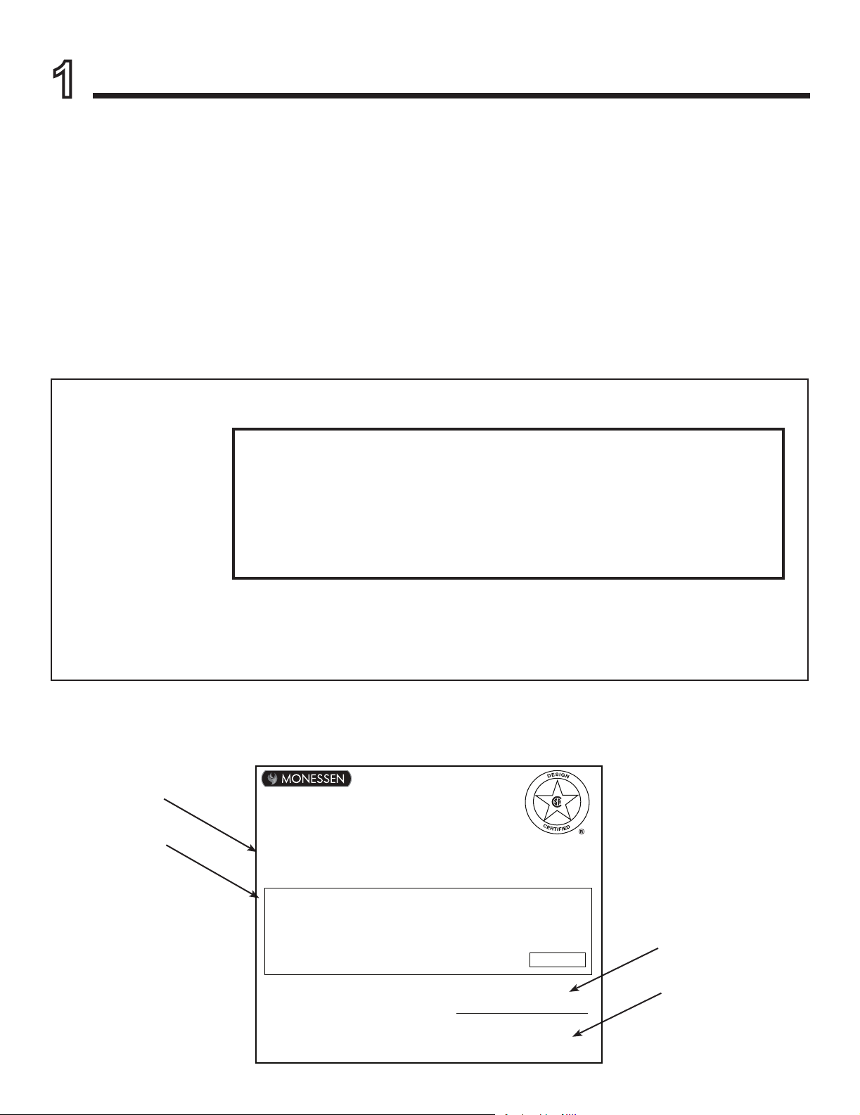
Listing Label Information/Location
Type of Gas
Gas and Electric
Information
The model information regarding your specic replace can be found on
the rating plate usually located in the control area of the replace.
Model Number
Serial Number
Monessen • AVFL60 Owner’s Manual • 4605-900 Rev. J • 03/21
3
Page 4
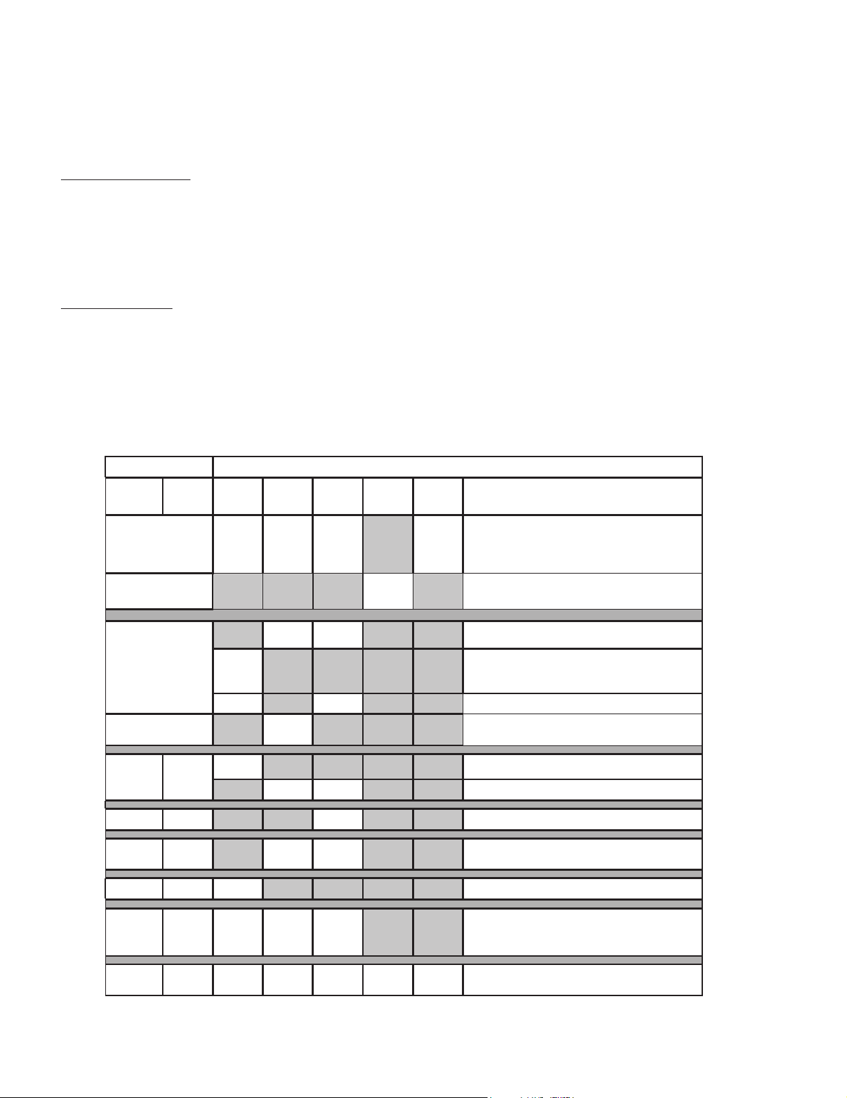
B. Limited Lifetime Warranty
recoverable under this Warranty is limited to the purchase price of the Product. This Warranty is transferable from the original purchaser
Component
►
Hearth & Home Technologies LLC
LIMITED LIFETIME WARRANTY
Hearth & Home Technologies LLC (“HHT”) extends the following warranty for HHT gas, wood, pellet and electric hearth appliances
(each a “Product” and collecvely, the “Product(s)”) and certain component parts set forth in the table below (“Component Part(s)”)
that are purchased from a HHT authorized dealer or distributor.
WARRANTY COVERAGE:
HHT warrants that the Products and their Component Parts will be free from defects in materials and workmanship for the applicable
period of Warranty coverage set forth in the table below (“Warranty Period”). If a Product or Component Parts are found to be
defecve in materials or workmanship during the applicable Warranty Period, HHT will, at its opon, repair the applicable Component
Part(s), replace the applicable Component Part(s), or refund the purchase price of the applicable Product(s). The maximum amount
to subsequent owners, but the Warranty Period will not be extended in duraon or expanded in coverage for any such transfer. This
Warranty is subject to condions, exclusions, and limitaons as described below.
WARRANTY PERIOD:
Warranty coverage begins at the date of installaon. In the case of new home construcons, Warranty coverage begins on the date of
rst occupancy of the dwelling or six months aer the sale of the Product(s) by an independent, authorized HHT dealer or distributor,
whichever occurs earlier. However, the Warranty coverage shall commence no later than 24 months following the date of Product
shipment from HHT, regardless of the installaon or occupancy date.
The term “Lifeme” in the table below is dened as: 20 years from the beginning date of warranty coverage for gas appliances, and 10
years from the beginning date of warranty coverage for wood and pellet appliances. These me periods reect the minimum expected
useful lives of the designated Component Parts under normal operang condions.
Warranty Period HHT Manufactured Appliances and Venting
Parts
5 years 1 year
6 years 3 years X Catalysts
7 years 3 years X X Manifold tubes, HHT Chimney and Terminations
Labor Gas Pellet Wood Electric Venting Component Parts Covered by this Warranty
All parts including handles, external enameled
components and other material except as covered by
2 Years
2 years
3 years X
X
X X Molded Refractory Panels, Glass Liners
X Vent Free Burners, Vent Free Logs
X1 Year X X X
X
X X
X X Castings, Medallions and Baffles
Warranty Conditions, Warranty Exclusions, and
Warranty Limitations listed
All parts except as covered by Warranty Conditions,
Warranty Exclusions, and Warranty Limitations listed
Igniters, Auger Motors, Electronic Components, and
Glass
Electrical components limited to modules, remotes/wall
switches, valves, pilots, blowers, junction boxes, wire
harnesses, transformers and lights (excluding light bulbs)
Firepots, burnpots, mechanical feeders/auger
assemblies
10 years 1 year X Burners, logs and refractory
Limited
Lifetime
1 Year
4021-645L 10/20
3 years X X X
None
X X X X X All purchased replacement parts
Monessen • AVFL60 Owner’s Manual • 4605-900 Rev. J • 03/214
Firebox and heat exchanger, FlexBurn® System
(engine, inner cover, access cover and fireback)
Page 1 of 2
Page 5

B. Limited Lifetime Warranty (continued)
4021-645L 10/20
WARRANTY CONDITIONS:
• Because HHT cannot control the quality of any Products sold by unauthorized sellers, this Warranty only covers Products that are
purchased through an HHT authorized dealer or distributor unless otherwise prohibited by law; a list of HHT authorized dealers
is available on the HHT branded websites.
• This Warranty is only valid while the applicable Product remains at the site of original installaon.
• This Warranty is only valid in the country in which the HHT authorized dealer or distributor that sold the applicable Product is
authorized to sell applicable Product.
• Contact your installing distributor or dealer for Warranty service. If the installing dealer or distributor is unable to provide
necessary parts, contact the nearest HHT authorized dealer or supplier. Addional service fees may apply if you are seeking
Warranty service from a dealer other than the dealer from whom you originally purchased the applicable Product.
• No HHT consumer should bear cost of warranty service or costs incurred while servicing warranty claims (i.e., travel, gas, or
mileage) when the service is performed within the terms of this Warranty. Check with your dealer or distributor in advance for
any costs to you when arranging a warranty call. Travel and shipping charges for parts are not covered by this Warranty.
WARRANTY EXCLUSIONS:
This Warranty does not cover the following:
• Changes in surface nishes as a result of normal use. As a heang appliance, some changes in color of interior and exterior surface
nishes may occur. This is not a aw and is not covered under the Warranty.
• Damage to printed, plated, or enameled surfaces caused by ngerprints, accidents, misuse, scratches, melted items or other
external sources and residues le on the plated surfaces from the use of abrasive cleaners or polishes.
• Repair or replacement of parts that are subject to normal wear and tear during the Warranty Period are not covered. These parts
include: paint, wood and pellet gaskets, rebricks, grates, ame guides, baeries and the discoloraon of glass.
• Minor expansion, contracon, or movement of certain parts causing noise. These condions are normal and complaints related to
this noise are not covered by this Warranty.
• Damages resulng from: (1) failure to install, operate, or maintain the applicable Product in accordance with the installaon
instrucons, operang instrucons, and lisng agent idencaon label furnished with the applicable Product; (2) failure to
install the applicable Product in accordance with local building codes; (3) shipping or improper handling; (4) improper operaon,
abuse, misuse, connued operaon with damaged, corroded or failed components, accident, or improperly/incorrectly performed
repairs; (5) environmental condions, inadequate venlaon, negave pressure, or draing caused by ghtly sealed construcons,
insucient make-up air supply, or handling devices such as exhaust fans or forced air furnaces or other such causes; (6) use of fuels
other than those specied in the operaon instrucons; (7) installaon or use of components not supplied with the applicable
Product or any other components not expressly authorized and approved by HHT; (8) modicaon of the appliance not expressly
authorized and approved by HHT in wring; and/or (9) interrupons or uctuaons of electrical power supply to the applicable
Product.
• Non-HHT venng components, hearth connecons or other accessories used in conjuncon with the applicable Product.
• Any part of a pre-exisng replace system in which an insert or a decorave gas applicable Product is installed.
• HHT’s obligaon under this Warranty does not extend to the Product’s capability to heat the desired space. Informaon is provided
to assist the consumer and the dealer in selecng the proper Product for the applicaon. Consideraon must be given to the
Product locaon and conguraon, environmental condions, insulaon and air ghtness of the structure.
This warranty is void if:
• The applicable Product has been over-red, operated in atmospheres contaminated by chlorine, uorine, or other damaging
chemicals. Over-ring can be idened by, but not limited to, warped plates or tubes, deformaon/warping of interior cast iron
structure or components, rust colored cast iron, bubbling, cracking and discoloraon of steel or enamel nishes.
• The applicable Product is subjected to prolonged periods of dampness or condensaon.
• There is any damage to the applicable Product due to water or weather damage which is the result of, but not limited to, improper
chimney or venng installaon.
LIMITATIONS OF REMEDIES AND LIABILITY:
• EXCEPT TO THE EXTENT PROVIDED BY LAW, HHT MAKES NO EXPRESS WARRANTIES OTHER THAN THE WARRANTY SPECIFIED
HEREIN. The owner’s exclusive remedy and HHT’s sole obligaon under this Warranty or in contract, tort or otherwise, shall be
limited to replacement of the Component Part(s), repair of the Component Part(s), or refund of the original purchase price of the
applicable Product(s), as specied above; provided, however, that (i) if HHT is unable to provide replacement of the Component
Part(s) and repair of the Component Part(s) is not commercially praccable or cannot be mely made, or (ii) the customer is
willing to accept a refund of the purchase price of the applicable Product(s), HHT may discharge all such obligaons by refunding
the purchase price of the applicable Product. In no event will HHT be liable for any incidental or consequenal damages caused
by defects in the applicable Product. Some States do not allow the exclusion or limitaon of incidental or consequenal damages,
so the above limitaon or exclusion may not apply to you. This Warranty gives you specic legal rights and you may also have
other rights which vary from State to State. THE DURATION OF ANY IMPLIED WARRANTY IS LIMITED TO DURATION OF THE
EXPRESSED WARRANTY SPECIFIED ABOVE FOR THE APPLICABLE PRODUCT. Some States do not allow limitaons on how long an
implied warranty lasts, so the above limitaon may not apply to you.
Page 2 of 2
Monessen • AVFL60 Owner’s Manual • 4605-900 Rev. J • 03/21
5
Page 6
Product Specic Information
2
A. Appliance Certication
MODEL: AVFL60NIP, AVFL60PIP
LABORATORY: CSA
TYPE: Unvented Gas Heater
STANDARD: ANSI Z21.11.2013
This product is listed to ANSI standards for “Unvented
Gas Heaters” and applicable sections of “Gas Burning
Heating Appliances for Manufactured Homes and Recre-
ational Vehicles”, and “Gas Fired Appliances for Use at
High Altitudes”.
NOTICE: This installation must conform with local codes.
In the absence of local codes you must comply with the
National Fuel Gas Code, ANSI Z223.1—latest edition in
the U.S.A.
B. BTU Specications
Models
(U.S. or Canada)
AVFL60NIP (0-4500 FT) 38,000 25,000 #44
AVFL60PIP (0-4500 FT) 37,000 29,000 #54
NOTE: For higher elevations please see page 9.
Maximum
Input BTU/h
Minimum
Input
BTU/h
Orice
Size (DMS)
NOT INTENDED FOR USE AS A PRIMARY HEAT SOURCE.
This appliance is tested and approved as either supplemental room heat or as a decorative appliance. It should not be
factored as primary heat in residential heating calculations.
Installation and service of this appliance should
be performed by qualied personnel. Hearth
& Home Technologies recommends HHT
Factory Trained or NFI certied professionals.
WARNING: This product and the
fuels used to operate this product (liquid
propane or natural gas), and the products
of combustion of such fuels, can expose
you to chemicals including benzene, which
is known to the State of California to cause
cancer and reproductive harm. For more
information go to: www.P65Warnings.
ca.gov.
Monessen • AVFL60 Owner’s Manual • 4605-900 Rev. J • 03/216
Page 7
3
Important Safety and Operating Information
A. Appliance Safety
WARNING! DO NOT operate replace before reading
and understanding operating instructions. Failure
to operate replace according to operating instructions
could cause re or injury.
WARNING! Choking Hazard! Keep media out of reach
of children.
• Alert children and adults to hazards of high temperatures.
High temperatures may ignite clothing or other
ammable materials.
• Clothing, furniture, draperies, and other flammable
materials must not be placed on or near the appliance.
Young children should be carefully supervised when they
are in the same room as the appliance. Toddlers, young
children and others may be susceptible to accidental
contact burns.
• A physical barrier is recommended if there are at risk
individuals in the house.
• To restrict access to a replace or stove, install an
adjustable safety gate to keep toddlers, young children,
pets and other at risk individuals out of the room and
away from hot surfaces.
• Install a switch lock or a wall/remote control with child
protection lockout feature.
• Keep remote controls out of reach of children.
• Never leave children alone near a hot replace, whether
operating or cooling down.
• Teach children to NEVER touch the replace.
• Consider not using the replace when children will be
present.
Contact your dealer for more information, or visit: www.
hpba.org/safety-information.
To prevent unintended operation when not using your replace for an extended period of time (summer months,
vacations, trips, etc):
• Remove batteries from remote controls.
• Turn o wall controls.
• Unplug 6 volt adapter plug.
Clear Space
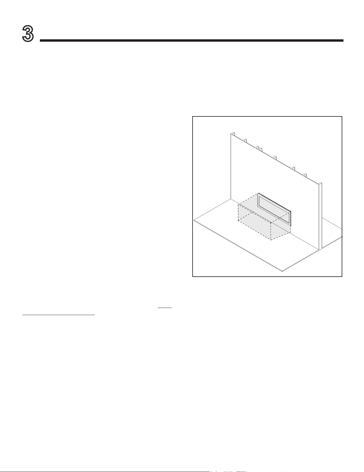
WARNING! DO NOT place combustible objects in front
of the replace. High temperatures may start a re. See
Figure 3.1.
Avoid placing candles, electronics and other heat-sensitive
objects on mantel or hearth. Heat may damage these
objects.
Note: See appliance Installation
Manual for hearth, mantel and
nishing requirements.
CLEAR SPACE
3 FT. IN FRONT
OF FIREPLACE
Figure 3.1 Clear Space
Over Firing
The appliance is considered to be over ring if the ames
are contacting the top of the rebox. Call a qualied service
technician to service the appliance.
Monessen • AVFL60 Owner’s Manual • 4605-900 Rev. J • 03/21
7
Page 8
Important Safety and Operating Information (continued)
OWNER
Please retain these instructions for future reference
.
WARNING
• Any change to this heater or its controls can be dangerous.
• Improper installation or use of the heater can cause serious injury or death from re, burns, explosion
or carbon monoxide poisoning.
• Do not allow fans to blow directly into the replace. Avoid any drafts that alter burner ame patterns.
• Do not use a blower insert, heat exchanger insert or other accessory, not approved for use with
this heater where applicable.
1. Due to high temperatures, the appliance should be
located out of trac and away from furniture and
draperies.
2. Children and adults should be alerted to the hazard
of high surface temperature and should stay away
to avoid burns or clothing ignition.
3. Young children should be carefully supervised when
they are in the same room with the appliance.
4. Do not place clothing or other ammable material
on or near the appliance.
5. Any safety screen or guard removed for servicing
an appliance, must be replaced prior to operating
the heater.
6. Installation and repair should be done by a qualied service person. To prevent malfunction and/or
sooting, an unvented gas heater should be cleaned
before use and at least annually by a professional
service person. More frequent cleaning may be
required due to excessive lint from carpeting, bedding materials, etc. It is imperative that control com-
partments, burners and circulating air passageways
be kept clean.
7. WARNING: Any change to this heater or its controls
can be dangerous.
8. Unvented gas heaters are a supplemental zone
heater. They are not intended to be the primary
heating appliance.
9. CARBON MONOXIDE POISONING: Early signs of
carbon monoxide poisoning are similar to the u with
headaches, dizziness and/or nausea. If you have these
signs, obtain fresh air immediately. Have the heater
serviced as it may not be operating properly.
10. The installation must conform with local codes or, in
the absence of local codes, with the National Fuel
Gas Code, ANSI Z223.l/NFPA54.
11. This unit complies with ANSI Z21.11.2 Unvented
Heaters, latest edition.
12. Do not install the heaters in a bathroom or bedroom.
13. Correct installation of the glass media, optional stone
and ceramic ber logs, proper location of the heater,
and annual cleaning are necessary to avoid potential
problems with sooting. Sooting, resulting from improper
installation or operation, can settle on surfaces outside
the replace. Refer to log placement instructions for
proper installation.
14. Avoid any drafts that alter burner ame patterns. Do not
allow fans to blow directly into replace. Do not place
a blower inside burn area of rebox. Ceiling fans may
create drafts that alter burner ame patterns. Sooting
and improper burning will occur.
15. Caution: Candles, incense, oil lamps, etc. produce
combustion by-products including soot. Vent-free
appliances will not lter or clean soot produced by
these types of products. In addition, the smoke and/
or aromatics (scents) may be reburned in the vent-free
appliance which can produce odors. It is recommended
to minimize the use of candles, incense, etc. while the
vent-free appliance is in operation.
16. This heater shall not be installed in a room or space
unless the required volume of indoor combustion air is
provided by the method described in the National Fuel
Gas Code, ANSI Z223.1/NFPA 54, the International
Fuel Gas Code or applicable local codes.
17. Keep room area clear and free from combustible materials, gasoline and other ammable vapors and liquids.
18. Unvented gas heaters emit moisture into the living
area. In most homes of average construction, this
does not pose a problem. In houses of extremely
tight construction, additional mechanical ventilation is
recommended.
19. During manufacturing, fabricating and shipping, various
components of this appliance are treated with certain
oils, lms or bonding agents. These chemicals are not
Monessen • AVFL60 Owner’s Manual • 4605-900 Rev. J • 03/218
Page 9
CLEAR SPACE
SECTION 3.A.
DECORATIVE DOORS
SECTION 4
GLASS ASSEMBLY
SECTION 4
OPERATION DURING
A POWER OUTAGE
SECTION 3.I
harmful but may produce annoying smoke and smells
as they are burned o during the initial operation of the
appliance; possibly causing headaches or eye or lung
irritation. This is a normal and temporary occurrence.
The initial break-in operation should last three to four
hours with the burner at the highest setting. Provide
maximum ventilation by opening windows or doors to
allow odors to dissipate. Any odors remaining after this
initial break-in period will be slight and will disappear
with continued use.
20. Input ratings are shown in BTU per hour and are for
elevations up to 2,000 feet. For elevations above 2,000
feet, input ratings should be reduced 4 percent for each
1,000 feet above sea level. Refer to the National Fuel
Gas Code.
21. The appliance and its appliance main gas valve must
be disconnected from the gas supply piping system
during any pressure testing of that system at test pres-
sures in excess of 1⁄2 psig (3.5 kPa).
22. The appliance must be isolated from gas supply piping
system by closing its equipment shuto valve during
any pressure testing of the gas supply piping system at
test pressures equal to or less than 1⁄2 psig (3.5 kPa).
23. Do not use this room heater if any part has been under
water. Immediately call a qualied service technician
to inspect the room heater and to replace any part of
the control system and any gas control which has been
under water.
24. Never burn solid fuels in a replace where a unvented
room heater is installed.
B. General Operating Parts
Figure 3.2 references the general operating parts of the
appliance and the section of this manual in which they are
discussed.
Figure 3.2 General Operating Parts
C. Fuel Specications
WARNING! Risk of Fire or Explosion! Appliance must
be set up for compatible gas type!
• This appliance is designed to operate on either natural
gas or propane. Make sure the appliance is compatible
with gas type selected for installation site.
BUILDING CODE INFORMATION
Adhere to all local codes or, in their absence, the latest
edition of THE NATIONAL FUEL GAS CODE ANSI Z223.1
or NFPA54 which can be obtained from:
American National Standards Institute, Inc.
1430 Broadway
New York, NY 10018
or
National Fire Protection Association, Inc.
Batterymarch Park
Quincy, MA 02269
Monessen • AVFL60 Owner’s Manual • 4605-900 Rev. J • 03/21
WARNING! Risk of Fire! Comply with all minimum
clearances to combustibles as specied in the installation
instructions.
9
Page 10
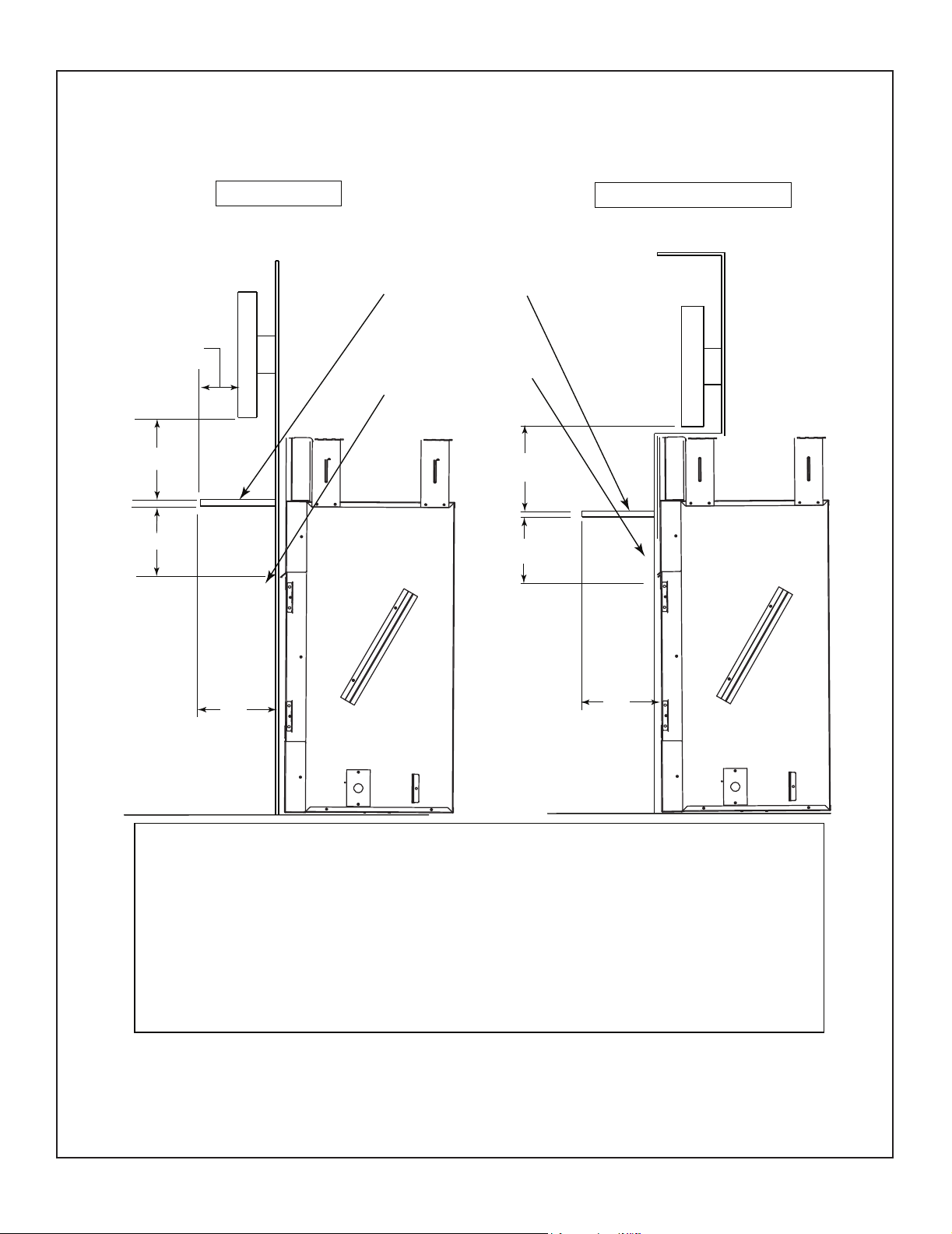
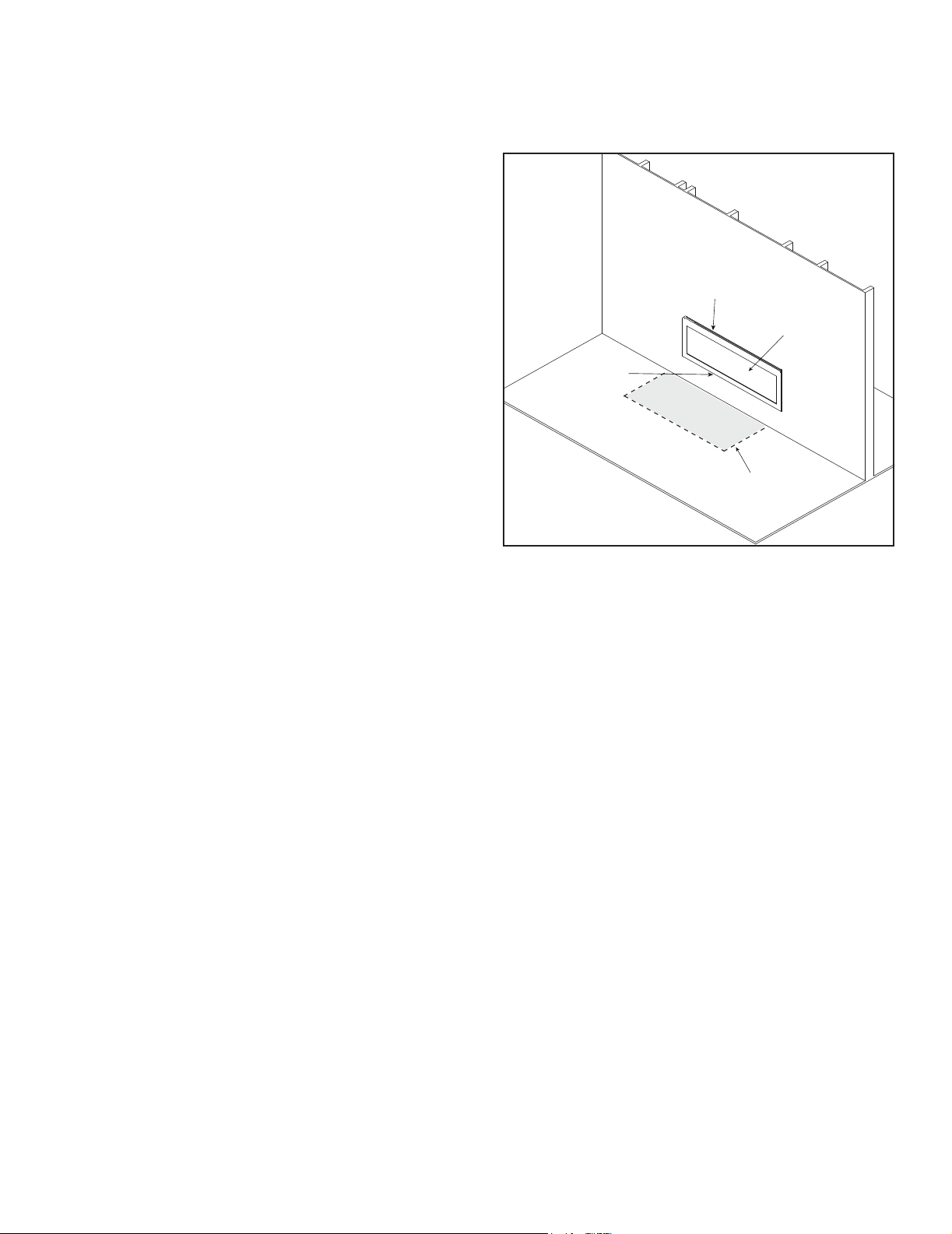
D. Good Faith Wall Surface TV Guidelines
Good Faith Guidelines for TV Installa�ons above a Typical Gas Fireplace
TV on the wall
TV
Mantel (required)
TV recessed into the wall
TV
4” Min.
28”
6” Min.
12”
Min.
Measured from top
of rebox opening.
4” Min.
28”
12”
Min.
Notes:
1. Mantel needs to be constructed entirely of non-combustible material if depth of mantel exceeds 12
inches at a height of 28 inches above the replace opening.
2. These are good faith recommended clearances only and not a guarantee of compliance with all TV
manufacturers’ maximum allowable operating temperatures.
3. Since every home has unique air ow characteristics and maximum allowable operating temperatures
can vary from manufacturer to manufacturer and from model to model, actual TV temperatures should be
validated at the time of each installation. TVs should not be used in situations where the actual TV
temperature exceeds the manufacturers’ maximum allowable operating temperatures identied in the
TV’s technical specications. Contact the TV’s manufacturer directly if you cannot locate this information
or have questions regarding the information.
Figure 3.3 Good Faith TV Guidelines
Monessen • AVFL60 Owner’s Manual • 4605-900 Rev. J • 03/2110
Page 11

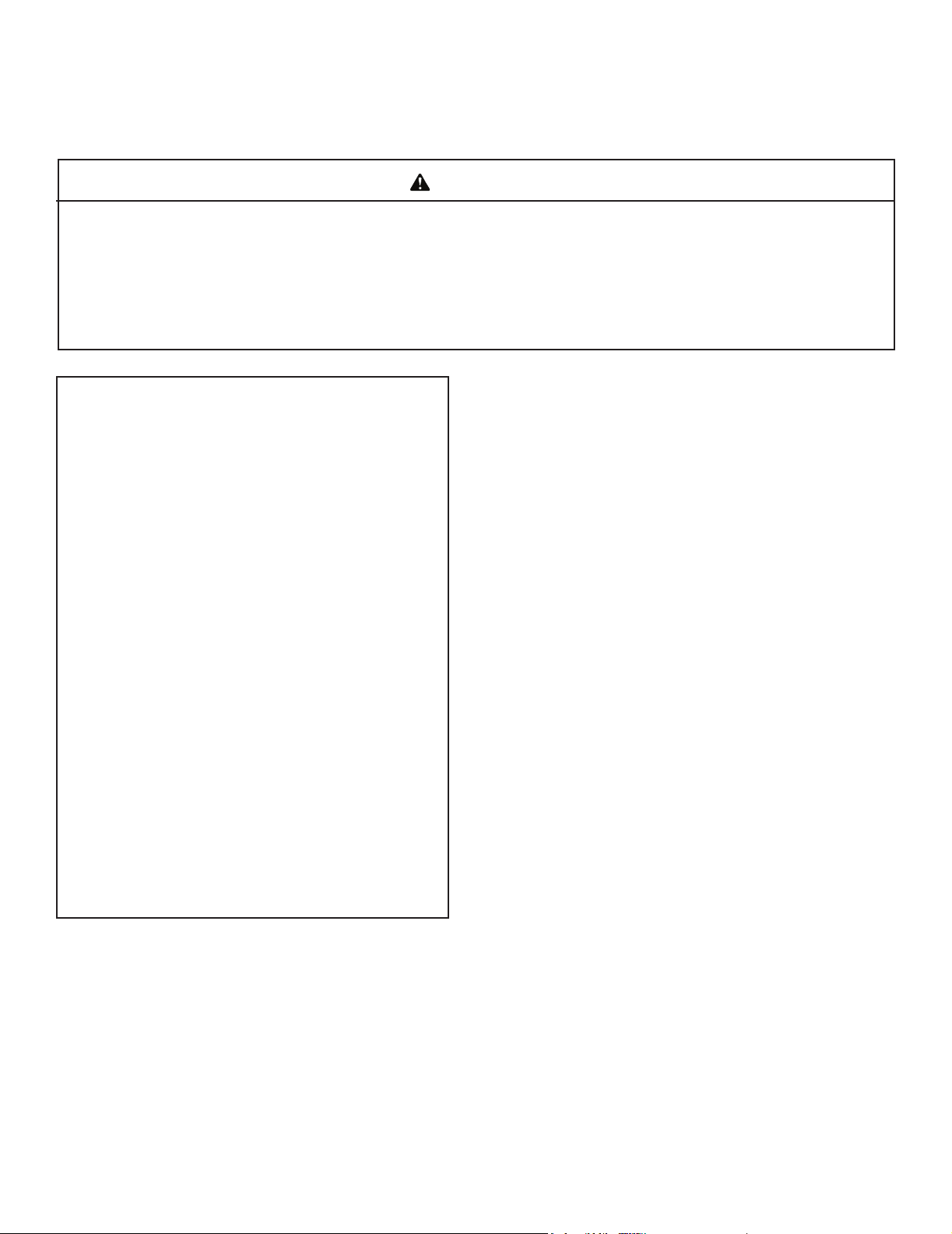
E. Before Lighting Appliance
Before operating this replace for the rst time, have a
qualied service technician:
• Verify all shipping materials have been removed from
inside and/or underneath the rebox.
• Review proper placement of re glass media.
• Ensure that there are no gas leaks.
• Ensure that the air deection glass is seated in the proper
position and that the screen is in place. See Figure 3.4.
Figure 3.4 Air Deection Glass
Deection glass tabs
Monessen • AVFL60 Owner’s Manual • 4605-900 Rev. J • 03/21
11
Page 12

F. Lighting Instructions (IPI)
FOR YOUR SAFETY READ BEFORE LIGHTING
WARNI NG: If you do not follow these instructions exactly, a fi re or explosion may result causing property damage, personal injury or loss of life.
A. This appliance is equipped with an intermittent pilot ignition (IPI) device which
automatically lights the burner. DO NOT try to light the burner by hand.
B. BEFORE LIGHTING, smell all around the appliance area for gas. Be sure to smell
next to the fl oor because some gas is heavier than air and will settle on the fl oor.
WHAT TO DO IF YOU SMELL GAS
• DO NOT try to light any appliance.
• DO NOT touch any electric switch; do not use any phone in your building.
1. This appliance is equipped with an ignition device which automatically
lights the burner. DO NOT try to light the burner by hand.
GAS
VALVE
1. Equipped with wall switch: Turn ON/OFF switch to OFF.
Equipped with remote or wall control: Press OFF button.
Equipped with thermostat: Set temperature to lowest setting.
• Immediately call your gas supplier from a neighbor’s phone. Follow the gas supplier’s instructions.
• If you cannot reach your gas supplier, call the fi re department.
C. DO NOT use this appliance if any part has been under water. Immediately call
a qualifi ed service technician to inspect the appliance and to replace any part of
the control system and any gas control which has been under water.
LIGHTING INSTRUCTIONS (IPI)
2. Wait fi ve (5) minutes to clear out any gas. Then smell for gas, including near the
fl oor. If you smell gas, STOP! Follow “B” in the Safety Information located on the
top of this label. If you do not smell gas, go to next step.
3. To light the burner:
Equipped
Equipped with remote or wall control: Press ON or FLAME button.
4. If the appliance does not light after three tries, call your service technician or gas
with wall switch: Turn ON/OFF switch to ON.
Equipped with thermostat: Set temperature to desired setting.
supplier.
TO TURN OFF GAS TO APPLIANCE
2. Service technician should turn off electric power to the control when performing
service.
4604-200
WARNING:
DO NOT CONNECT LINE VOLTAGE (110/120 VAC OR 220/240 VAC) TO THE CONTROL VALVE.
Improper installation, adjustment, alteration, service or maintenance can cause
injury or property damage. Refer to the owner’s information manual provided with
this appliance. For assistance or additional information, consult a qualifi ed installer,
service agency or the gas supplier.
This appliance needs fresh air for safe operation and must be installed so there are
provisions for adequate combustion and ventilation air.
CAUTION:
Keep burner and control compartment clean. See installation and operating instructions accompanying appliance.
Hot while in operation. DO NOT touch. Keep children, clothing, furniture, gasoline
and other liquids having fl ammable vapors away.
NOT FOR USE WITH SOLID FUEL
follow the National Fuel Gas Code, ANSIZ223.1/ NFPA 54, or the National Gas and
Propane Installation code, CSA B149.1.
For additional information on operating your
Hearth & Home Technologies fi replace, please refer to www.fi replaces.com.
.
,enon fi ;yna fi ,sedoc lacol htiw ecnadrocca ni dellatsni eb tsum ecnailppa sihT
4604-201
Monessen • AVFL60 Owner’s Manual • 4605-900 Rev. J • 03/2112
Page 13

G. Initial Use
Initial Break-in Procedure
• The replace should run three to four hours continuously
on high.
• Turn the replace o and allow it to completely cool.
This cures the materials used to manufacture the replace.
NOTICE! Open windows for air circulation during replace break-in.
• Some people may be sensitive to smoke and odors.
• Smoke detectors may activate.
H. Heat Management
Burn Rate
The Artisan model has a variable burn rate which is controlled by the remote control. Therefore the ame height
is adjustable.
The ame height may be adjusted as desired by locating
the ame option on the remote control and adjusting up or
down to desired ame height.
I. Operation During A Power Outage
The IntelliFire™ Plus ODS intermittent pilot ignition system
comes with a battery backup system that enables the
system to operate in a power outage. The system oers
seamless transition from household AC power to battery
backup. A factory-installed battery pack is located in the
control cavity of the appliance. See Figure 3.5. Battery
longevity and performance will be aected by long term
exposure to the service temperatures of this appliance.
Wireless Remote:
• Remote receiver is integrated into the ignition module
• Use the remote to turn the appliance on.
• To preserve battery life, do not use the HI/LO ame or
THERMOSTAT options.
Ignition Module:
• Locate the ignition module in the control cavity.
• Slide the ON/REMOTE/OFF switch to the ON position.
NOTICE: Some functionality will be lost when using
battery backup including remote control, lights, or any
other auxiliary functions that require household 110-120
VAC power.
To Return to Operation Using Electrical (AC) Power
Standard Wall Switch or Factory-Installed ON/OFF
Switch:
• Toggle the switch to OFF.
• Remove the batteries from the battery tray.
Wireless Remote:
• Slide the ON/REMOTE/OFF switch to the REMOTE
position.
• Remove the batteries from the battery tray.
Ignition Module:
• Slide the ON/REMOTE/OFF switch to the REMOTE
position.
• Remove the batteries from the battery tray.
NOTICE: Batteries should only be used as a power source
in the event of an emergency power outage. Batteries
should not be used as a primary long-term power source.
To Operate Fireplace Using Battery Power (DC):
1. Access the control cavity of the appliance. See Figure
3.5 for location. Lift the barrier screen o of the
appliance.
2. Locate the battery tray and insert four AA cell batteries.
See Figure 3.5. Battery polarity must be correct or
module damage will occur. A complete wiring diagram
is included in the electrical section of the appliance
installation manual.
3. Turn the appliance on according to the instructions
below for the appropriate type of control:
Standard Wall Switch or Factory-Installed ON/OFF
Switch:
• Toggle the switch as you would under normal
circumstances.
3.4 Control Cavity Location (Cut away front view only for
location purpose, no direct access from front)
Gas Valve
3.5 Battery Tray Location - Top View
Control
Module
Battery
Tray
Monessen • AVFL60 Owner’s Manual • 4605-900 Rev. J • 03/21
13
Page 14

IntelliFire Plus Remote Control
4
RC300
IntelliFire Plus™ Multifunction Remote Control
Installation & Operating Instructions
Hearth & Home Technologies disclaims any responsibility
for, and the warranty will be voided by, the following actions:
• Installation and use of any damaged system component.
• Modication of the system component.
• Installation other than as instructed by Hearth & Home
Technologies.
• Installation and/or use of any component part not approved
by Hearth & Home Technologies.
Any such action may cause a re hazard.
• Read, understand and follow these instructions for safe
installation and operation.
Introduction
The RC300 multifunctional remote control is designed
to control lighting of the main burner, ame height and
interior dome lighting. The RC300 is equipped with
thermostat functions which can automatically control
the temperature in the room in which it is installed. The
control is only for use with the Hearth & Home Technologies IntelliFire Plus™ system (IPI). The AUX300
module is rated for 120 VAC, 60 Hz, and is required for
operation of this remote control device.
Installation Precautions
This remote control is tested and safe when installed in
accordance with this installation manual. Do not install
any components that may be damaged.
Do not modify, disassemble, or substitute any of the com-
ponents included with this kit. Installation of this unit must
be done by a qualied service technician.
Placement of this remote control may aect performance.
An assessment of the space should be done prior to in-
stallation for optimum performance.
Determine Location
Determine the location for the remote control. The selected
location should be in the same space as the gas replace.
Never place this unit in a separate room. The remote control
must be placed within 30 feet (9.14 m) of the replace but
should not be exposed to extreme heat.
The RC300 is approved for interior installation and should
not be used in exterior applications.
• Keep remote control out of reach of children.
FCC Requirements
WARNING! Risk of Fire! Changes or modications to
this unit not expressly approved by the party responsible
for compliance could void the user’s authority to operate
the equipment.
Note: This equipment has been tested and found to
comply with the limits for a Class B digital device, pur-
suant to Part 15 of the FCC Rules. These limits are
designed to provide reasonable protection against
harmful interference in a residential installation. This
equipment generates, uses, and can radiate radio
frequency energy and, if not installed and used in accordance with the instructions, may cause harmful in-
terference to radio communications. However, there is
no guarantee that interference will not occur in a partic-
ular installation. If this equipment does cause harmful
interference to radio or television reception, which can
be determined by turning the equipment o and on, the
user is encouraged to try to correct the interference by
one or more of the following measures:
• Reorient or relocate the receiving antenna.
• Increase the separation between the equipment and
receiver.
• Connect the equipment into an outlet on a circuit dif-
ferent from that to which the receiver is connected.
• Contact the dealer or an experienced radio TV technician for help.
Changing Temperature Scale
To change the temperature display between Celsius and
Fahrenheit, remove the battery cover from the back of the
remote control and slide the switch to your desired temperature scale (see Figure 1). The screen will automatically change the indicators on the room temperature and
set temperature portion.
Figure 1. Temperature scale
Monessen • AVFL60 Owner’s Manual • 4605-900 Rev. J • 03/2114
Page 15

Installation of Remote Control Housing
CAUTION! Risk of Fire! DO NOT install damaged or
modied components. Warranty will be voided if damaged
or modied components are installed.
Kit components: One remote control, two #6 screws, two
wall anchors, 3 AAA batteries and one AUX300 module. If
batteries are properly installed the remote will turn on
1. Remove remote control components from packaging.
2. Remove battery cover from the back of the remote by
sliding it down and install 3 AAA batteries.
To prevent unintended operation when not using your replace for an extended period of time (summer months,
vacation, trips, etc):
• Remove batteries from remote control.
• Unplug switching adapter and remove back-up batteries.
3. Secure the remote control housing on a at wall surface using the two screws and wall anchors provided.
See Figure 2.
5. Close the housing door. See Figure 4.
Figure 4. Mounting Remote Control Housing
Figure 2. Mounting Remote Control Housing
4. Place remote control inside housing. See Figure 3.
Figure 3. Remote in Housing
Monessen • AVFL60 Owner’s Manual • 4605-900 Rev. J • 03/21
15
Page 16

Programming the RC300 to the Control Module
CAUTION! Risk of burns! DO NOT program the remote
control to the control module when replace is hot.
• Verify the ON/OFF/REMOTE switch is in the REMOTE
position. Green LED light will blink three times and wall
switch will beep once 5 seconds later when ready. See
Figure 5.
• Using a small item (such as a paper clip) press and
release the LEARN button located near the ON/OFF/
REMOTE switch. See Figure 5.
• Control module will beep once and LED will blink green
for 10 seconds.
• While the LED is blinking, press the POWER button on
the remote control. A double beep will come out of the
control module to indicate that it has been programmed
successfully.
NOTICE: Up to three remote controls can be programmed
into the control module. Simply press a button on the other
remote controls during the 10 second programming process
to add another remote into the system. It is recommended
to program only one RC300 remote control.
To clear memory in the control module, use a small item
(such as a paper clip) to press and release the LEARN
button. Control module will beep once and LED will blink
green for 10 seconds DO NOT press any buttons on the
remote during the ten seconds that the green LED blinks.
The memory will be cleared. Note that the RC300 will not
be programmed if it’s in STANDBY mode. Press the ON/
OFF button twice to switch to IDLE mode.
REMOTE POSITION
Figure 5. Programming RC300
Monessen • AVFL60 Owner’s Manual • 4605-900 Rev. J • 03/2116
Page 17

V
Menu
V
V
V
Display Screen
FIREPLACE STATUS
THERMOSTAT
THERMOSTAT DESIRED
TEMP SETTING
Idle When Remote is in ON Mode
The remote control will go into an idle mode if no buttons are pressed within 5 seconds. Press any button to
resume full functionality. In idle mode, only active functions will show on the screen.
FLAME HEIGHT
FAN SPEED
ADJUSTABLE
AUXILIARY
ADJUSTABLE
OUTPUT (ON/OFF)
CONSTANT PILOT
TIMER DISPLAY/FUNCTION
Figure 8. RC300 Display Screen
Function Buttons
Use POWER button to turn the unit on and o.
Menu
Use MENU button to display the menu functions.
Only functions that can be activated will be
displayed. For example: Flame Height will not
be displayed when the remote status is OFF.
Select
Use the SELECT button to select the current
feature.
V
Use the UP and DOWN arrows to toggle
through the menu functions and value selec-
V
tions in the submenus.
CHILD LOCK
INDICATOR
TRANSMISSION
INDICATOR
LOW BATTERY
INDICATOR
FUNCTION LEVEL
INDICATOR
ROOM TEMP
DISPLAY
Figure 9. RC300 Idle Mode
Standby mode
The remote control will go into a standby mode if no buttons are pressed within 5 minutes. Press the POWER
button to reactivate the remote control to ON mode. Ac-
tive functions will be displayed
Figure 10. RC300 Standby Mode
Monessen • AVFL60 Owner’s Manual • 4605-900 Rev. J • 03/21
17
Page 18

About ON Mode
• All functions can be accessed when the remote control
is in the ON mode.
• Only active functions will be displayed when the remote
control is in the ON mode.
About OFF Mode
Only the following functions can be accessed in the OFF
mode:
• AUX1
• AUX2
Only active functions will be displayed when the remote
control is in the OFF mode.
Turning On the Fireplace
• Press the POWER button to turn the replace ON. The
replace will rst ignite the pilot. Once the pilot ame is
established the main burner will be lit.
NOTICE: Whenever the replace is cycled from OFF to
ON, the main burner will light on high for 10 seconds before
returning to the previous user setting.
Adjusting Flame Height
• Press the MENU button to activate the menu.
• Using the UP and DOWN arrows highlight the FLAME
icon and press SELECT.
• Use the UP and DOWN arrows to adjust the FLAME
HEIGHT, then press SELECT. The FLAME HEIGHT
can be adjusted to 5 dierent settings.
NOTICE: FLAME HEIGHT will not be adjustable for rst
ten seconds when replace is turned on.
NOTICE: The system will remember the previous FLAME
HEIGHT setting and will automatically adjust after 10
seconds.
Adjusting Thermostat
• Press the MENU button to activate the menu.
• Using the UP and DOWN arrows highlight the THERMO
icon and press SELECT.
• Use the UP and DOWN arrows to turn the THERMO ON
or OFF, then press SELECT (the SET TEMP will start
blinking). Using the UP and DOWN arrows select the
desired temperature and press SELECT.
NOTICE: If the THERMO function is on, the SET TEMP
can be adjusted at any time by pressing the UP and DOWN
arrows.
NOTICE: As the ROOM TEMP (RT) approaches SET
TEMP (ST), the remote system will automatically adjust
the ame height. If the RT rises above ST, the replace
will shut down the main burner. After this, the replace will
turn back on after the RT drops below the ST.
NOTICE: The system requires a two degree Fahrenheit
or higher temperature dierence between RT and ST for
the replace to turn on.
NOTICE: The system will remember the previous TEMPERATURE setting when THERMOSTAT mode is cycled
ON or OFF.
NOTICE: If your installation includes an optional wired ON/
OFF wall switch, it should be in the OFF position when
using the RC300 in thermostat mode.
Adjusting Timer
• Press the MENU button to activate the menu.
• Using the UP and DOWN arrows highlight the TIMER
icon and press SELECT.
• Use the UP and DOWN arrows to turn the TIMER ON
or OFF, then press SELECT. Using the UP and DOWN
arrows select the desired set time and press SELECT.
Timer operates in increments of 15, 30, 45, 60, 90, 120
and 180 minutes.
NOTICE: Some models use xed valves, which cannot
be adjusted.
AUX1 Function (Top Dome Lighting)
• Press the MENU button to activate the menu.
• Using the UP and DOWN arrows highlight the AUX1 icon
and press SELECT.
• Use the UP and DOWN arrows to adjust the AUX1 output,
then press SELECT. The AUX1 function can be adjusted
to 4 dierent settings: HI, MED, LOW and OFF.
Monessen • AVFL60 Owner’s Manual • 4605-900 Rev. J • 03/2118
Setting the Child Lock
• Press and hold the MENU and UP arrow buttons simul-
taneously for 4 seconds to enable or disable the child
lock feature.
NOTICE: No functions will be usable until child lock feature
is disabled.
Page 19

Power Outage
• If replace battery backup system IS installed at time of
power outage, replace operation will not be interrupted.
• If replace battery backup system IS NOT installed at
time of power outage, replace will shut o. To resume
replace operation, install battery backup.
NOTICE: Battery polarity must be correct or module
damage will occur.
Manual Fireplace Shuto
In the unlikely event that the remote wall switch malfunctions and will not turn o the replace, call your dealer
for service assistance. In the meantime, you may choose
one of the following actions to turn o the replace:
CAUTION! Risk of burns! Fireplace surfaces are hot
when operating and during cool down. Use care and wear
gloves when opening the front and accessing compo-
nents inside the replace.
Check remote screen for battery level indicator, replace
the batteries if low battery is indicated (See Figure 9).
The replace may be manually shut down by one of the
following methods:
Turn o the control module:
• Open or remove the decorative front to access the control
module.
• Move switch to OFF (See Figure 7).
Disconnect power to the control module:
• Open or remove the decorative front to access power
cord to the junction box and/or back-up batteries.
• Unplug the control module and/or remove back-up
batteries.
Shut o gas to the control:
• Open or remove the decorative front and locate the gas
shut-o valve to the left of the gas control.
• Rotate the valve 90 degrees to turn o gas supply.
Turn o power to the replace (if back-up batteries are
not installed):
• Unplug unit from electrical source, if you cannot unplug
then:
• Locate house circuit breaker for replace.
• Turn o the circuit breaker.
LED Control Operation
• The AVFL60 series appliance comes standard with
a two (2) button LED control panel located under the
access panel. See Figure 10.
NOTE: The optional IPIWK wall switch kit oers the
option to relocate the buttons for LED control into a wall
control box as shown in Figure 11.
Monessen • AVFL60 Owner’s Manual • 4605-900 Rev. J • 03/21
19
Page 20

LED Control
• Multi-colored LED lights - These two (2) buttons turn
LEDs ON (HI/MED/LO) and OFF function and cycle
through the color selection.
1. Color Fade - This setting will cycle through the colors
shown below at a slower rate.
2. Color Fade Slow - This setting will cycle through the
colors shown below at a slower rate.
3. Pause Color - This setting will pause the slow color
fade at any color in the color wheel.
4. Solid Color Selection - This setting will cycle through
each color in order:
• Blue
• Violet
• Red
• Yellow
• Green
• Cyan
• White
CAUTION! Risk of Electrical Shock! Avoid touching
wires and electrical components in appliance control cavity.
Rocker Switch
On/Hi/Med/Lo/
O
Color Selection
Figure 11 Wall Control Switch (IPIWK)
Figure 12 Access Panel
ODS
Adapter
Battery
Backup
Aux
Led
Buttons
Monessen • AVFL60 Owner’s Manual • 4605-900 Rev. J • 03/2120
Valve
Control
Module
ODS
Module
Page 21

Frequently Asked Questions/Troubleshooting
Symptom Possible Cause Corrective Action
Batteries Verify batteries are functional and installed correctly.
Remote control is in Child
Remote control will not transmit
Control module will not take
commands from remote control
Fireplace is on but will not shut o
with the remote control
Lock mode
Buttons not being pressed
rmly
Control module is not in
“REMOTE” mode
Control module and remote
control are not programmed
to each other
Control module is un-
plugged. In case of power
outage, backup batteries
are depleted or missing
External wired wall switch
Remote control or control
module failure
Disengage Child Lock mode.
Press button rmly for one to two seconds to ensure transmission to module.
Ensure module switch is set to REMOTE.
The control module will beep when it successfully receives a
command. If it does not beep, clear module memory and reprogram wall switch.
If the transmission indicator comes on when power button is
pressed, verify that the control module is plugged in the replace junction box located in the controls area. Also verify that
the batteries are installed in the battery pack.
The replace cannot be turned o by remote if an external
wired switch is installed and in the ON position. Turn external
wall switch to OFF.
At control module, turn o replace by sliding the ON/OFF/REMOTE switch to OFF. Warning! Risk of Burns! Fireplace is hot.
Use caution when accessing module.
Please contact your Hearth & Home Technologies dealer with any questions or concerns.
For the location of your nearest Hearth & Home Technologies dealer,
please visit www.hearthnhome.com.
Monessen • AVFL60 Owner’s Manual • 4605-900 Rev. J • 03/21
21
Page 22

5
Maintenance and Service
Any safety screen or guard removed for servicing must be
replaced prior to operating the replace.
When properly maintained, your replace will give you
many years of trouble-free service. Contact your dealer
to answer questions regarding proper operation, trouble-
shooting and service for your appliance. Visit www.monessenhearth.com to locate a dealer. We recommend annual service by a qualied service technician.
A. Maintenance: Frequency and Tasks
The matrix below is an overview of maintenance tasks to
be performed on the appliance. Sections B and C give
details and instructions needed to assist the appropriate
person in performing the tasks.
Task Frequency To be completed by
Surrounds Annually
Remote Control Seasonally
Light Bulbs As Needed
Pilot Inspection
& Cleaning
Log/Media
Inspection
Firebox
Inspection
Control
Compartment &
Firebox Top
Burner Ignition
& Operation
Annually
Annually
Annually
Annually
Annually
Homeowner
Qualied Service
Technician
Surrounds
Frequency: Annually
By: Homeowner
Tools needed: Protective gloves, stable work surface
• Assess condition of screen and replace as necessary.
• Inspect for scratches, dents or other damage and replace
as necessary.
• Vacuum and dust surfaces.
Remote Control
Frequency: Seasonally
By: Homeowner
Tools needed: Replacement batteries and remote con-
trol instructions.
• Locate remote control transmitter and receiver.
• Verify operation of remote. Refer to remote control
operation instructions for proper calibration and setup
procedure.
• Replace batteries as needed in remote transmitters and
battery-powered receivers.
• Place remote control out of reach of children.
If not using your replace for an extended period of time
(summer months, vacations/trips, etc), to prevent unintended operation:
• Remove batteries from remote controls.
• Unplug 6 volt adapter plug on IPI models.
B. Maintenance Tasks: Homeowner
Installation and repair should be done by a qualied service
technician only. The replace should be inspected before
use and at least annually by a professional service person.
The following tasks may be performed annually by the
homeowner. If you are uncomfortable performing any of
the listed tasks, please call your dealer for a service appointment.
More frequent cleaning may be required due to lint and
dust from carpeting, pet dander or other factors. Control
compartment, burner and circulating air passageway of
the replace must be kept clean.
CAUTION! Risk of Burns! The replace should be turned
o and cooled before servicing.
Monessen • AVFL60 Owner’s Manual • 4605-900 Rev. J • 03/2122
Page 23

C. Maintenance Tasks: Qualied Service
Technician
The following tasks must be performed by a qualied service technician.
Pilot
Frequency: Annually
By: Qualied Service Technician
Tools needed: Small soft brush, pipe cleaner
• Inspect and remove dust, spider webs and lint
• Gently run pipe cleaner through air intake port
Firebox
Frequency: Annually
By: Qualied Service Technician
Tools needed: Protective gloves, sandpaper, steel wool,
cloths, mineral spirits, primer and touch-up paint.
• Inspect for paint condition, warped surfaces, corrosion
or perforation. Sand and repaint as necessary.
• Replace replace if rebox has been perforated.
Bulb Installation
Turn OFF the main power supply before performing any service work on the unit, including installing or replacing light bulbs.
CAUTION
TOP LIGHT LOCATION
Figure 5.1 Top Light Position
Control Compartment and Firebox Top
Frequency: Annually
By: Qualied Service Technician
Tools needed: Protective gloves, vacuum cleaner, dust
cloths
• Vacuum and wipe out dust, cobwebs, debris or pet hair.
Use caution when cleaning these areas. Screw tips that
have penetrated the sheet metal are sharp and should
be avoided.
• Remove all foreign objects.
• Verify unobstructed air circulation.
Dome Light Bulb Replacement
1. Remove three screws holding the left light cover in
place.
See Figure 5.2.
2. Insert (1) bulb provided into socket
3. Replace top light cover with three screws
4. Repeat on right side light cover
Light cover
screws
Figure 5.2 Top Light Screws
Monessen • AVFL60 Owner’s Manual • 4605-900 Rev. J • 03/21
23
Page 24

Accessing the LEDs
1. Turn o gas supply and disconnect main power to appliance before performing any maintenance.
2. Remove glass deection shield and place on a clean
at surface.
3. Remove all media from hearth surface.
4. Remove screen to access LED strips inside the LED
channels.
• Make sure LED strips are clear of any debris.
• If removing the LED strips simply peel from LED chan-
nels. Make sure channels are clear before placing
new LED strips with self adhesive into the channels.
• To clean the LED strips, use a damp cloth and carefully wipe the strips. NOTE: The channel is sharp
and contains screws extruding into the channel.
Burner Ignition and Operation
Frequency: Annually
By: Qualied Service Technician
Tools needed: Protective gloves, vacuum cleaner, whisk
broom, ashlight, voltmeter, indexed drill bit set, and a
manometer.
• Verify burner is properly secured and aligned with pilot
or igniter.
• Clean o burner top, inspect for plugged ports, corrosion
or deterioration. Replace burner if necessary.
• Inspect for lifting or other ame problems.
• Inspect orice for soot, dirt and corrosion. Verify orice
size is correct. See Service Parts List for proper orice
sizing.
• Verify manifold and inlet pressures. Adjust regulator as
required.
• Inspect pilot ame pattern and strength. See Figure 5.4
and 5.5 for proper pilot ame pattern. Clean or replace
orice spud as necessary.
• Verify IPI millivolt output. Replace as necessary.
• Verify that there is not a short in ame sense circuit
by checking continuity between pilot hood and ame
sensing rod. Replace pilot as necessary.
Leg support
bracket
LED control
module
Figure 5.3
LED transformer
Appliance
Control Box
Thermocouple
for Natural Gas
Figure 5.4 Correct Pilot Flame Appearance
Thermocouple
for Natural Gas
Thermocouple
for LP
Thermocouple
for LP
Figure 5.5 Incorrect Pilot Flame Appearance
Monessen • AVFL60 Owner’s Manual • 4605-900 Rev. J • 03/2124
Page 25

6
Frequently Asked Questions and Troubleshooting
A. Frequently Asked Questions
ISSUE SOLUTION
When rst operated, this replace may release an odor for the rst several hours. This
is caused by the burning o of any oils remaining from manufacturing or from nishing
materials or adhesives used around the replace during installation. Follow the Initial
Use instructions on page 13.
Odor from replace
Metallic noise
Wall above appliance feels
hot to the touch
Contact your dealer for additional information regarding operating and troubleshooting. Visit
www.monessenhearth.com to locate a dealer.
Odor may also come from dust, pet dander, deodorizing room sprays and other foreign
debris that collects on the surface of the burner and media when the unit is not in use
for an extended period of time. To avoid odors cause by these substances, have your
qualied service technician thoroughly inspect and clean your replace prior to the rst
use of each season.
No action is necessary. Noise is cause by metal expanding and contracting as it heats
up and cools down, similar to the sound produced by a furnace or heating duct. This
noise does not aect the operation or longevity of the replace.
No action is necessary. This appliance ships with a non-combustible material. Specica-
tions of the non-combustible material are listed in the Installer’s Manual for this appli-
ance.
B. Troubleshooting
With proper installation, operation and maintenance your gas appliance will provide years of trouble-free service. If you
do experience a problem, this troubleshooting guide will assist a qualied service technician in the diagnosis of a problem
and the corrective action to be taken. This troubleshooting guide can only be used by a qualied service technician. Con-
tact a dealer to arrange a service call by a qualied service technician.
IntelliFire™ Plus ODS Ignition System
SYMPTOM POSSIBLE CAUSE CORRECTIVE ACTION
Verify “S” wire (orange) for ignitor are connected to correct terminals on module and pilot assembly.
Verify no loose connections or electrical shorts in wiring
from module to pilot assembly. Verify connections un-
derneath pilot assembly are tight; also verify igniter and
ame sense wires are not grounding out to metal chassis, pilot burner, pilot enclosure, mesh screen if present,
or any other metal object.
Verify gap of igniter to right side of pilot hood. The gap
should be approximately .17 in. or 1/8 in. (3 mm).
Verify that transformer is installed and plugged into
module. Check voltage of transformer at connection to
module. Acceptable readings of a good transformer are
between 3.2 and 2.8 volts AC.
Remove and reinstall the wiring harness that plugs into
module. Verify there is a tight t. Verify pilot assembly
wiring to module. Remove and verify continuity of each
wire in wiring harness. Replace any damaged components.
Verify black ground wire from module wire harness is
grounded to metal chassis of appliance.
Pilot won’t light. The ignition/module makes noise,
but no spark.
Pilot won’t light. There is no
noise or spark.
Incorrect wiring
Loose connections or electrical
shorts in the wiring.
Ignitor gap is too large
No power, transformer installed
incorrectly.
A shorted or loose connection
in wiring conguration or wire
harness.
Junction box wiring Verify that 110-120 VAC power is “ON” to junction box.
Module not grounded
Monessen • AVFL60 Owner’s Manual • 4605-900 Rev. J • 03/21
25
Page 26

IntelliFire™ Plus ODS Ignition System (Continued)
Pilot sparks, but will not
light.
Pilot lights but continues to
spark, and burner will not
ignite. (If the pilot continues to spark after the pilot
ame has been lit, ame
rectication has not occurred.)
Gas supply.
Ignitor gap is too large.
Module is not grounded.
Pilot valve solenoid
A short or loose connection in
ame sensing rod.
Poor ame rectication or contaminated ame sensing rod.
Module is not grounded.
Damaged pilot assembly or
contaminated ame sensing rod
Verify that incoming gas line ball valve is “open”. Verify
that inlet pressure reading is within acceptable limits.
Verify gap of igniter to right side of pilot hood. The gap
should be approximately .17 in. or 1/8 in. (3 mm).
Verify module is securely grounded to metal chassis of
appliance.
Verify that 1.5 to 1.8 VDC is supplied to pilot solenoid
from module. If below 1.5 volts, replace module. If 1.5
volts or greater, replace valve.
Verify all connections to wiring diagram in manual. Verify
connections underneath pilot assembly are tight. Verify
connections are not grounding out to metal chassis, pilot
burner, pilot enclosure or screen if present, or any other
metal object.
Verify correct pilot orice is installed and gas inlet is set
to pressure specications. Check pilot for soot. Clean if
necessary.
Verify module is securely grounded to metal chassis of
appliance. Verify that wire harness is rmly connected to
the module.
Verify that ceramic insulator around the ame sensing
rod is not cracked, damaged, or loose. Verify connection
from ame sensing rod to white sensor wire. Polish ame
sensing rod with ne steel wool to remove any contaminants that may have accumulated on ame sensing rod.
Verify continuity with a multimeter with ohms set at lowest range. Replace pilot if any damage is detected.
Module
Turn wall control to OFF position. Remove ignitor wire “I”
from module. Turn wall control to ON position. If there is
no spark at “I” terminal module must be replaced. If there
is a spark at “I” terminal, module is ne.
Monessen • AVFL60 Owner’s Manual • 4605-900 Rev. J • 03/2126
Page 27

C. Troubleshooting – Screen/LEDs/Control Panel
SYMPTOM POSSIBLE CAUSE CORRECTIVE ACTION
Check that GFCI breaker is operating as intended and is
not tripped. Verify that AC power has been connected to
the appliance. Ensure that both the 3V IPI control module
power supply as well as the LED power supply are securely
plugged into the appliance junction box.
Check appliance for loose/corroded connections or shorted
wires.
Check for 12VDC from power supply. If 12VDC is present,
LED strip is bad.
LED lights will not turn
on (appliance or control
panel)
No AC power to appliance
Faulty wiring
LED failure
Halogen bulb will not
turn on
Appliance does not
turn on when control
panel on/o switch is
depressed
Power supply failure
Control panel failure Replace switch assembly
No AC power to appliance
Faulty wiring
Bulb failure Change bulb (see page 24)
Power supply failure
No AC power to appliance
Faulty wiring
Control panel failure Replace control panel
Check for 12VDC. If no 12VDC is present, power supply is
bad
Check that GFCI breaker is operating as intended and is
not tripped. Verify that AC power has been connected to
the appliance. Ensure that both the 3V IPI control module
power supply as well as the LED power supply are securely
plugged into the appliance junction box.
Check appliance for loose/corroded connections or shorted
wires.
Check for 12VDC. If no 12VDC is present, power supply is
bad
Check that GFCI breaker is operating as intended and is
not tripped. Verify that AC power has been connected to the
appliance. Ensure that both the 3V IPI control module power
supply as well as the 12V screen and LED power supply are
securely plugged into the appliance junction box.
Check appliance for loose/corroded connections or shorted
wires.
Monessen • AVFL60 Owner’s Manual • 4605-900 Rev. J • 03/21
27
Page 28

7
Reference Materials
A. Accessories
Install approved accessories per instructions included
with accessories. Contact your dealer for a list of approved accessories.
WARNING! Risk of Fire and Electric Shock! Use ONLY
Hearth & Home Technologies-approved optional accessories with this appliance. Using non-listed accessories
could result in a safety hazard and will void the warranty.
• Glass Media
-Diamond
-Bronze
-Onyx
-Sapphire
• Wall Mount Switch Kit (IPIWK)
This kit allows the appliance to be turned on and o with
a simple rocker switch and provides LED control convenience.
• Driftwood Log Set (AVFL60DLS)
This log set adds a new twist to the contemporary look of
the AVFL60 with a three piece set.
• Optional Finish Kits
The AVFL60 has three optional nish kits that will customize your unit.
-AVFL60TKI - Black textured inside t trim kit
-AVFL60CFVC - Contemporary veined copper face
-AVFL60CFBT - Contemporary black textured face
• Optional Stone Kit (SKAVFL60)
-The look of water tumbled stones adds interest and
appeal to your replace.
Monessen • AVFL60 Owner’s Manual • 4605-900 Rev. J • 03/2128
Page 29

B. Service Parts
►
Service Parts
60” Artisan Vent Free Linear Fireplace
AVFL60NIP, AVFL60PIP
Beginning Manufacturing Date: June 2017
Ending Manufacturing Date: Active
1
2
3
7
4
5
8
6
9
10
11
12
13
Part number list on following page.
16
15
14
02/21
Monessen • AVFL60 Owner’s Manual • 4605-900 Rev. J • 03/21
29
Page 30

Service Parts
IMPORTANT: THIS IS DATED INFORMATION. Parts must be ordered from a dealer or
distributor. Hearth and Home Technologies does not sell directly to consumers.
Provide model number and serial number when requesting service parts from your
dealer or distributor.
ITEM DESCRIPTION COMMENTS PART NUMBER
1 Stand O, Tall
2 Mounting Bracket
3 Reector Light Assembly
4 Bulb Socket Assembly
Halogen Bulb, 90 Watt, 120 Volt
5 Lense, Clear
6 Accent Light Assembly
7 Face Top Board
8 Eyebrow
9 Steel Mesh, Rear
10 Steel Mesh, Front
11 Access Panel Assembly
12 Support, Glass
13 Ceramic Glass, 48” x 4”
14 Screen Assembly
15 Engine Stand
16 Junction Box
AVFL60NIP, AVFL60PIP
Beginning Manufacturing Date: June 2017
Ending Manufacturing Date: Active
Qty 4 req SRV4090-511
Qty 2 req SRV4602-164
Qty 2 req 20306017K
Qty 2 req 20302295
Qty 2 req SRV4602-302 Y
Qty 2 req 20305773
Qty 2 req 20305516K
SRV4605-302
SRV4605-122
SRV4605-130
SRV4605-129
SRV4605-013
Qty 2 req 20305518K
SRV4605-301
SRV4605-009
Qty 2 req SRV4605-128
SRV4021-013 Y
Stocked
at Depot
#17 Black Magic Glass
17
17 Black Magic Glass, Left Side
18 Black Magic Glass, Rear
19 Black Magic Glass, Right Side
Bracket, Black Magic Glass
Additional service part numbers appear on following page.
18
19
SRV4605-305
SRV4605-303
SRV4605-304
Qty 2 req SRV4605-144
Monessen • AVFL60 Owner’s Manual • 4605-900 Rev. J • 03/2130
Page 31

Service Parts
IMPORTANT: THIS IS DATED INFORMATION. Parts must be ordered from a dealer or distributor. Hearth and
Home Technologies does not sell directly to consumers. Provide model number and serial number when
requesting service parts from your dealer or distributor.
ITEM DESCRIPTION COMMENTS PART NUMBER
AVFL60NIP, AVFL60PIP
Beginning Manufacturing Date: June 2017
Ending Manufacturing Date: Active
#20 Engine Assembly
20.1
20.4
Stocked
at Depot
20.5
20.2
20.3
20.8
20.7
20.6
20.9
20.10
20.18
20.17
20.16
20.15
20.13
20.11
20.1 LED Light Strip
20.2 Burner Assembly
20.3 Pilot Assembly
20.4 Venturi
20.5 Gasket, Venturi
20.6 Pilot Regulator
20.7 Tube, Tee to Valve
20.8 Gas Valve Assembly
20.9 LED Panel Switch
20.10 LED Control Module
20.11 Piezo Wire Assembly, VF-SCS
20.12 Lighting Harness
20.13 Wire, 8K-1 to Adapter Box
20.14 Wire, ODS Module to Adapter Box
20.15 Wire Harness Bulbs
20.16 Wire, Thermocouple Module
Additional service part numbers appear on following page.
20.12
20.14
20.20
20.19
20.21
20.28
20.22
20.27
20.23
20.24
20.26
20.25
Qty 2 req 20308557K
SRV4605-011 Y
NG SRV26D2529 Y
LP SRV14D0476 Y
Qty 2 req 45D0600
Qty 2 req SRV45D0032 Y
NG Only SRV14D0469 Y
SRV4605-135 Y
NG SRV4604-300 Y
LP SRV4604-301 Y
Qty 2 req 20308586K Y
SRV4121-035 Y
20303256K Y
SRV4601-201 Y
SRV4604-305 Y
SRV4604-304 Y
SRV78D1077 Y
SRV20301890 Y
Monessen • AVFL60 Owner’s Manual • 4605-900 Rev. J • 03/21
31
Page 32

Service Parts
IMPORTANT: THIS IS DATED INFORMATION. Parts must be ordered from a dealer or distributor. Hearth and
Home Technologies does not sell directly to consumers. Provide model number and serial number when
requesting service parts from your dealer or distributor.
ITEM DESCRIPTION COMMENTS PART NUMBER
20.17 Aux Input Cable
20.18 Transformer, 6 Volt Wall
20.19 Pilot Tube
20.20 Tube, Tee to Injector
20.21 Injectors ( Qty 2 req )
20.22 Control Module
20.23 ODS Module
20.24 ODS Adapter Box
20.25 Battery Pack
20.26 Aux Box
20.27 LED Power Module
20.28 Flex w/Shuto
Remote Control Assembly
Remote Control
AVFL60NIP, AVFL60PIP
Beginning Manufacturing Date: June 2017
Ending Manufacturing Date: Active
20308587K Y
SRV2326-131 Y
SRV20304115 Y
Qty 2 req 20308556K
NG SRV59D0062 Y
LP SRV20H3146 Y
2166-338 Y
SRV20303179 Y
SRV4604-302 Y
SRV2166-323 Y
SRV2166-335 Y
20308559K Y
SRV69D0030 Y
RC300-MON
SRV4605-307 Y
Stocked
at Depot
Monessen • AVFL60 Owner’s Manual • 4605-900 Rev. J • 03/2132
Page 33

C. Contact Information
Monessen, a brand of Hearth & Home Technologies
7571 215th Street West, Lakeville, MN 55044
www.monessenhearth.com
Please contact your dealer with any questions or concerns.
For the location of your nearest dealer,
please visit www.monessenhearth.com
- NOTES -
________________________________________________________________________________
________________________________________________________________________________
________________________________________________________________________________
________________________________________________________________________________
________________________________________________________________________________
________________________________________________________________________________
________________________________________________________________________________
________________________________________________________________________________
________________________________________________________________________________
NOTICE
DO NOT DISCARD THIS MANUAL
• Important operating
and maintenance
instructions included.
• Read, understand and follow
these instructions for safe
installation and operation.
• Leave this manual with
party responsible for use
and operation.
This product may be covered by one or more of the following patents: (United States) 6601579, 6769426, 6863064,
7077122, 7074035, 7098269, 7234932, 7258116, 7322819, 7422011, 7470729, 7726300, 8147240, 9625149 or other U.S.
and foreign patents pending.
2000-945E
Printed in U.S.A. - Copyright 2016
Monessen • AVFL60 Owner’s Manual • 4605-900 Rev. J • 03/21
33
 Loading...