

Page 1
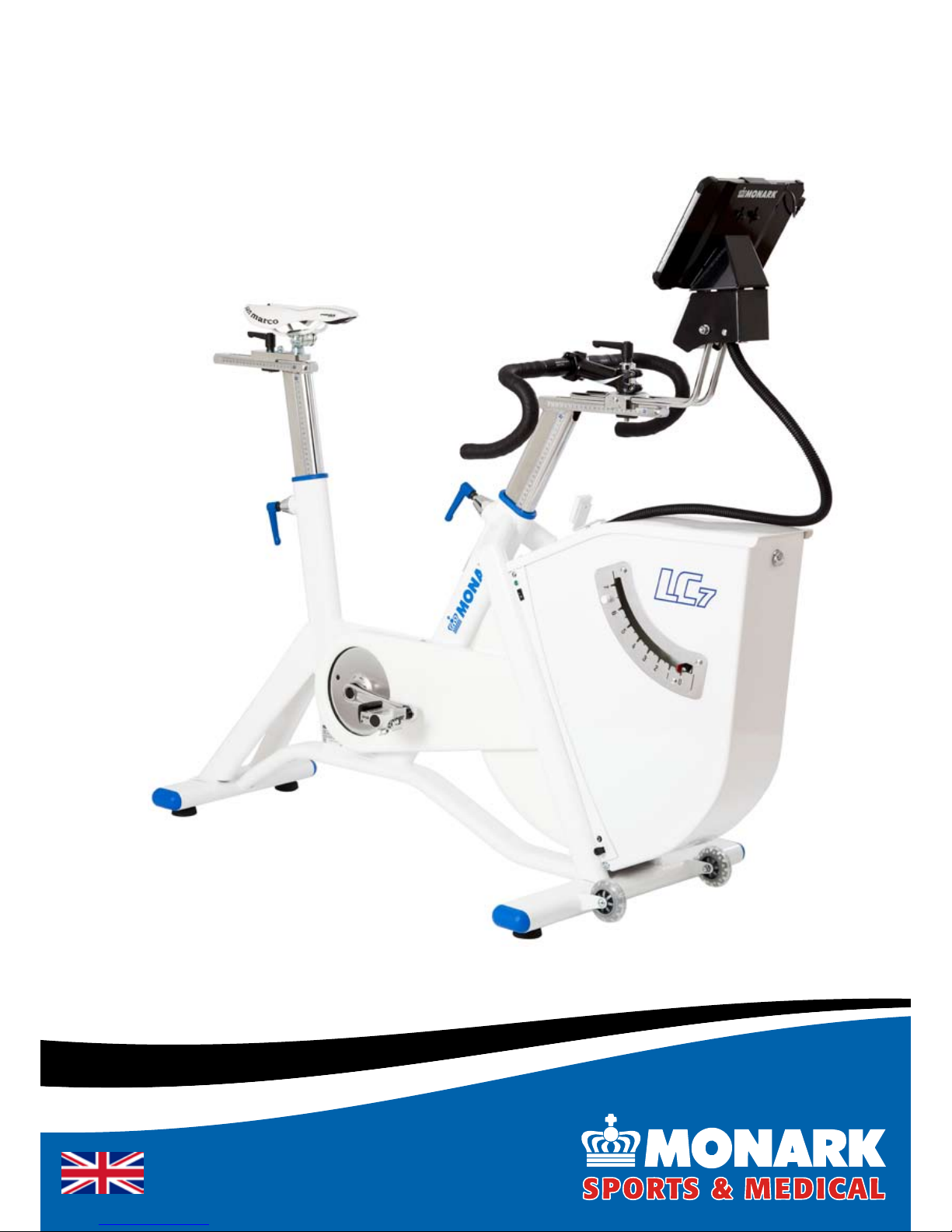
Manual for LC6 / LC7
Page 2

Page 3

Monark Exercise AB ����������������������������������������������������������������������4
Product Information ����������������������������������������������������������������������6
Facts........................................................................................................... 6
PC software ................................................................................................ 6
Serial number ............................................................................................. 6
Settings ������������������������������������������������������������������������������������������8
User settings ..............................................................................................8
Initial operation ........................................................................................... 8
Cycle adjustments ...................................................................................... 8
Operating Instruction ��������������������������������������������������������������������9
Power on crank or ywheel ........................................................................ 9
Control of the bike ...................................................................................... 9
Measured quantities ................................................................................... 9
Meter instructions ..................................................................................... 10
Keys and functions ................................................................................... 10
Connection to controller ������������������������������������������������������������� 11
Setting command type (PC or ECG device) ............................................. 11
What command type (cmd type) is set? ................................................... 12
Connection to PC ..................................................................................... 12
Terminal Mode PC .................................................................................... 12
Management of connections .................................................................... 13
Validation �������������������������������������������������������������������������������������14
Checking the pulse function ..................................................................... 14
Validation of force ..................................................................................... 14
Zero adjustment of scale .......................................................................... 15
Calibration ................................................................................................ 15
Calibration ������������������������������������������������������������������������������������16
Calibration electronics .............................................................................. 16
Electronic calibration - with the pendulum ................................................ 16
Testing with LC6 / LC7 ����������������������������������������������������������������18
Heart Rate (telemetry) .............................................................................. 19
Test person enforcement .......................................................................... 19
Reviewing results ..................................................................................... 20
Troubleshooting guide ����������������������������������������������������������������21
Operation interferences ............................................................................ 22
Where to obtain additional information ������������������������������������23
Service ������������������������������������������������������������������������������������������24
Warning .................................................................................................... 24
Warranty ................................................................................................... 24
Service check and Maintenance .............................................................. 24
Batteries ................................................................................................... 25
Flywheel bearing ...................................................................................... 25
Crank bearing ........................................................................................... 25
Transportation .......................................................................................... 25
Replacement of brake belt .......................................................................25
Brake belt contact surface ........................................................................ 25
Chain 1/2“ x 1/8“ ....................................................................................... 26
Freewheel sprocket .................................................................................. 27
Spare parts list ����������������������������������������������������������������������������28
2014 MONARK EXERCISE AB, Vansbro, Sweden
Contents
Important
Read the manual carefully before using the cycle
and save it for future use.
Page 4

LC6 / LC7
4
Monark Exercise AB
Monark has 100 years’ experience of bicycle production. The Monark tradition has yielded
know-how, experience, and a real feel for the product and quality. Since the early 1900s,
Monark’s cycles have been living proof of precision, reliability, strength and service. Those
are the reasons why we are now the world leader in cycle ergometers and the market leader
in Scandinavia in transport cycles.
We manufacture, develop and market ergometers and exercise bikes, transport bikes and
specialized bicycles. Our largest customer groups are within health care, sports medicine,
public authorities, industry and postal services.
For more information: http://www.monarkexercise.se
Page 5
LC6 / LC7
5
Thank you for choosing a test cycle from Monark!
Ideal position is important for performance to reach its maximum. LC6/LC7 has a brand new frame
that is adjustable in all directions. The frame also allows the Q-factor to be reduced, which further
increases the possibilities for a perfect performance. The new setting options, along with an upgraded
braking system, make Monark's renowned bike even better.
LC6/LC7 gives the conditions; the rest is up to the rider.
In today's society we are used to customizing our machines and tools for our own needs. The
same applies to LC6/LC7. Through intelligent solutions parts can be customized according to user
requirements. LC6/LC7 is also prepared for additional equipment, channels behind the covers make it
easy to install different equipment for different needs. LC6/LC7 is a great bike as it is, with additional
equipment, it can be even better.
Force is a strong word which brings many associations. For us, force is interesting when it can be
measured and calibrated. For a brake-force to be correct, regardless of the system, it must be calibrated
and controlled. On LC6/LC7 the brake system and calibration have been updated so that it is safer
and more accurate. It is also quicker to adjust and has more options in that it is speed-independent,
but can be switched into constant braking force as an alternative.
Monark has always been known for the bikes measurement accuracy, now it's even better.
Page 6
LC6 / LC7
6
Facts
Technical data power adaptor, LC6 and LC7
Input voltage: 220-240 V AC; 650 mA; 50/60 Hz.
Output voltage: 24 V DC switching adapter alt. 18
V AC.
(Sweden, 18 V, Art. No: 9339-67, other countries
incl. USA, 24 V, Art. No: 9339-66)
Polarity: Optional AC
NOTE! The power adaptor must be CE-marked if
original adaptor is replaced.
Technical details
Length 1405-1630 mm
Width 640 mm
Height
(max at display) LC6 1530 mm
LC7 1500 mm
Height
(max at saddle) 1240 mm
Weight 77 kg
Weight flywheel 20 kg
Max user weight 180 kg
Painting Industrial powder coating
Rust protection Zinc-based basic powder
coating on exposed areas
Power output
Continuous (50-100 rpm) 4-700 W
Peak (at rpm) 1400 W (200 rpm)
Smallest increment 1 W
Features
VO•
2
submax test
Training/test protocols (custom)•
HRC•
VO•
2
controlled
External control via RS232 (USB with the includ-•
ed adaptor)
VO•
2
max test
ECG worktest•
Included
Calibration weight 4 kg•
Chest belt Polar T34, 5 kHz•
Tool kit•
Power adaptor•
USB-Serial converter•
0-modem cable (RS232)•
Product Information
LC6 is delivered with a document •
holder.
LC7 is delivered with an integrated •
computer with 10" touch screen,
Windows, Bluetooth and WiFi.
NOTE!
Use of the product may involve considerable physical
stress. It is therefore recommended that people who
are not accustomed to cardiovascular exercise or
who do not feel completely healthy, should consult
a physician for advice.
Serial number
The serial number is placed according to Fig: Overview
at page 7.
NOTE! Before you start using the bike - remember to
remove the pendulum locking devices and protective
tape on the flywheel.
The bike can be used at maximum load
without any time limit.
PC software
(not LC7)
If you need a PC software to do exercise tests on the
bike, our software is available for free download from
our website: www.monarkexercise.se.
Page 7
5
6
10
7
5
4
3
14b
14a
1
13
12
11
9a
2
16
17
18
19
9b
15
9
8
LC6 / LC7
7
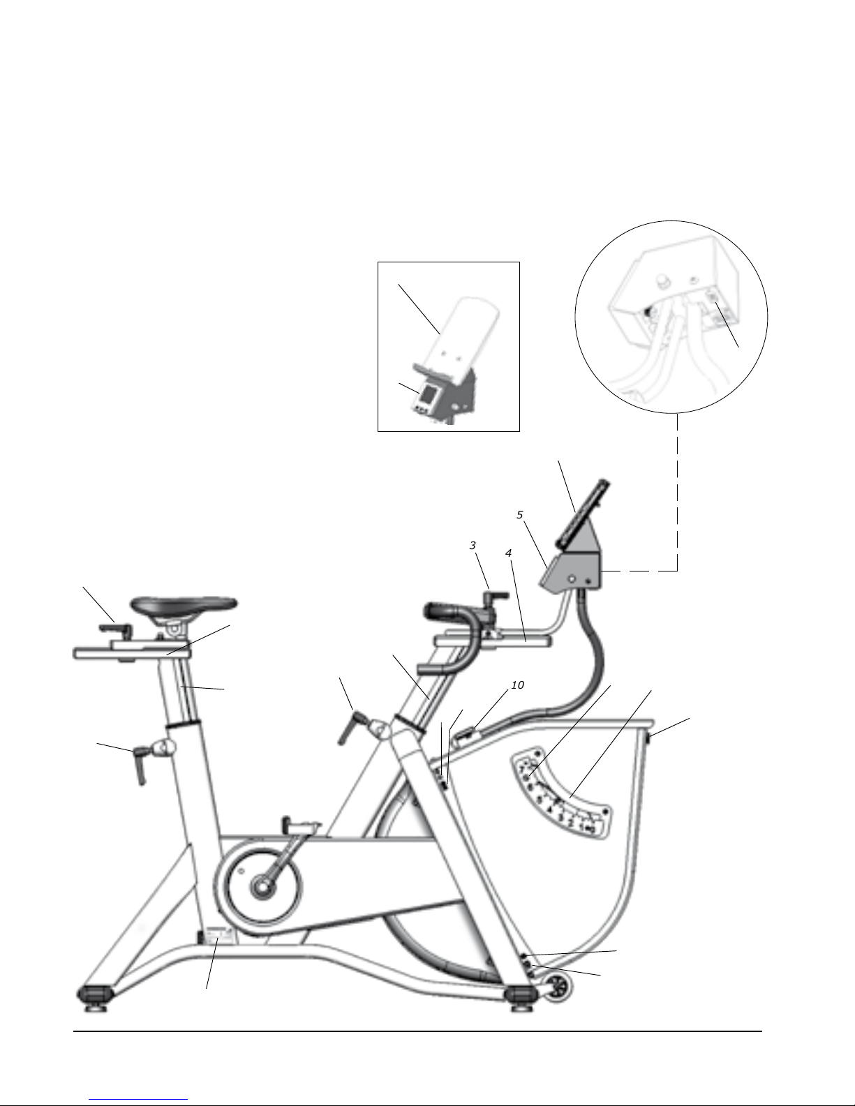
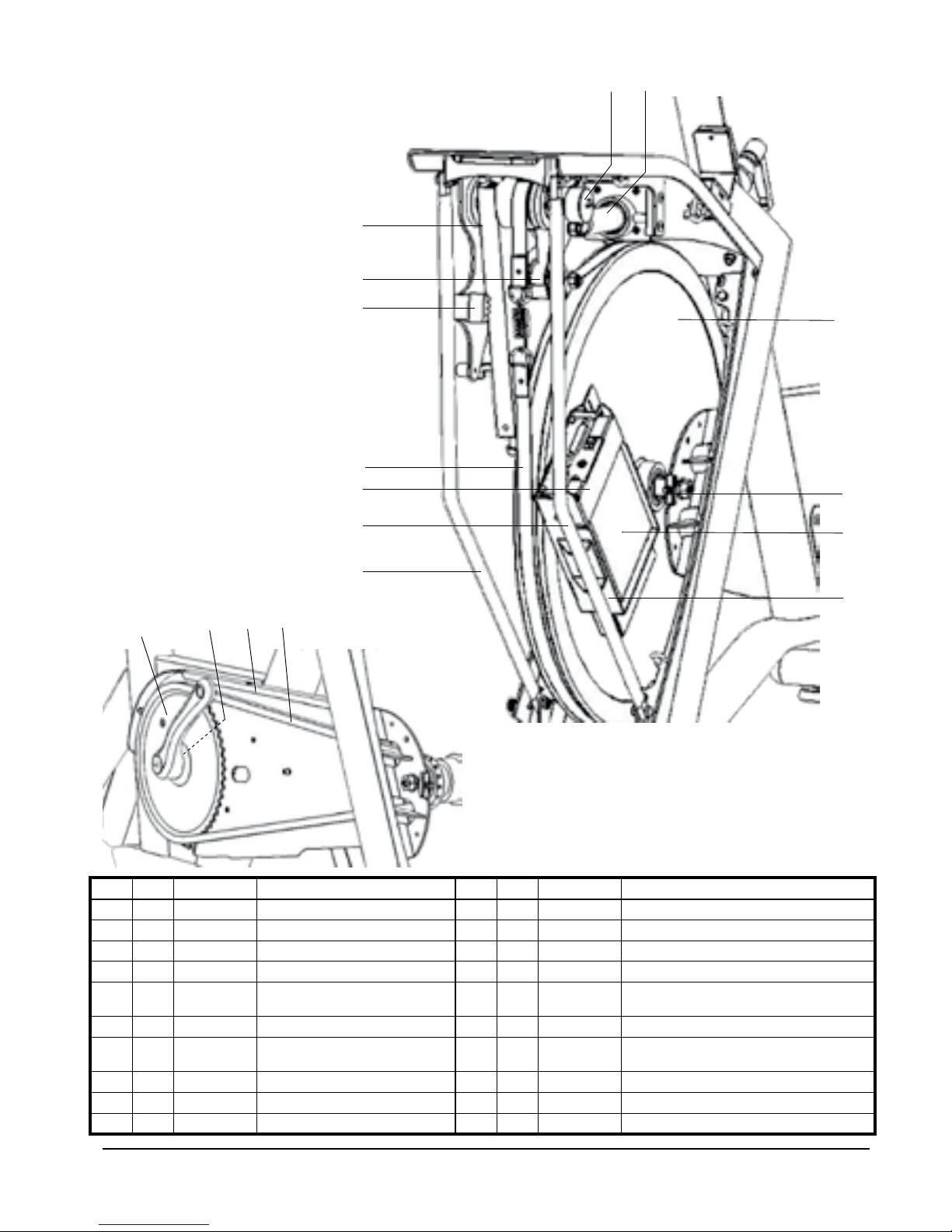
Fig: Overview
1) Knob for horizontal adjustment of saddle
2) Scale for horizontal adjustment of saddle
3) Knob for horizontal adjustment of handlebar and display
4) Scale for horizontal adjustment of handlebar
5) RPM meter
6) LC6 Document holder
7) LC7 Display with integrated computer
8) RS232 connection
9a) LED
9b) Power switch
10) Pulse receiver
11) Screw for adjustment Kp-scale
12) Kp-scale
13) Locking for front cover
14a) Power connection
14b) Locking for cable (power adaptor)
15) Serial number
16) Locking handle for height adjustment saddle
17) Scale for height adjustment saddle
18) Locking handle for height adjustment handlebar
19) Scale for height adjustment handlebar
Page 8

1
4
3
2
LC6 / LC7
8
Settings
User settings
Crank Steel, 170 mm standard,
172,5 mm optional
Pedals 9/16”, SPD/LOOK
compatible
Saddle Racing
Seat post Vertically: 530-940 mm
Horizontally: 200 mm
Handlebar Racing,
Ø31,8 mm at clamp
Handlebar stem Vertically: 500-910 mm
Horizontally: 200 mm
Distance saddle - handlebar 140-840 mm
Cycle adjustments
Seat height should be adjusted to a comfortable
position. The appropriate height is to have the knee
slightly bent when the sole of the foot is centred over
the pedal axle with the pedal in the bottom position.
When adjusting the saddle height and vertical
position, loosen the respective locking handles. See
Fig: Overview at page 7.
The handlebar setting should be in a comfortable
position when cycling. During longer exercise sessions
it is recommended to occasionally change handlebar
position. The handlebar can be adjusted both
horizontally and vertically. This is done by loosening
the respective locking handles. See Fig: Overview at
page 7.
NOTE! Be sure that the stem and seat post are inserted
to at least 100 mm in the frame. This is marked with
“MAX” on the stem.
Initial operation
LC6 / LC7 is mechanically calibrated in the factory.
The user may wish to verify this by performing the
mechanical calibration of the pendulum weight. See
”Electronic calibration”.
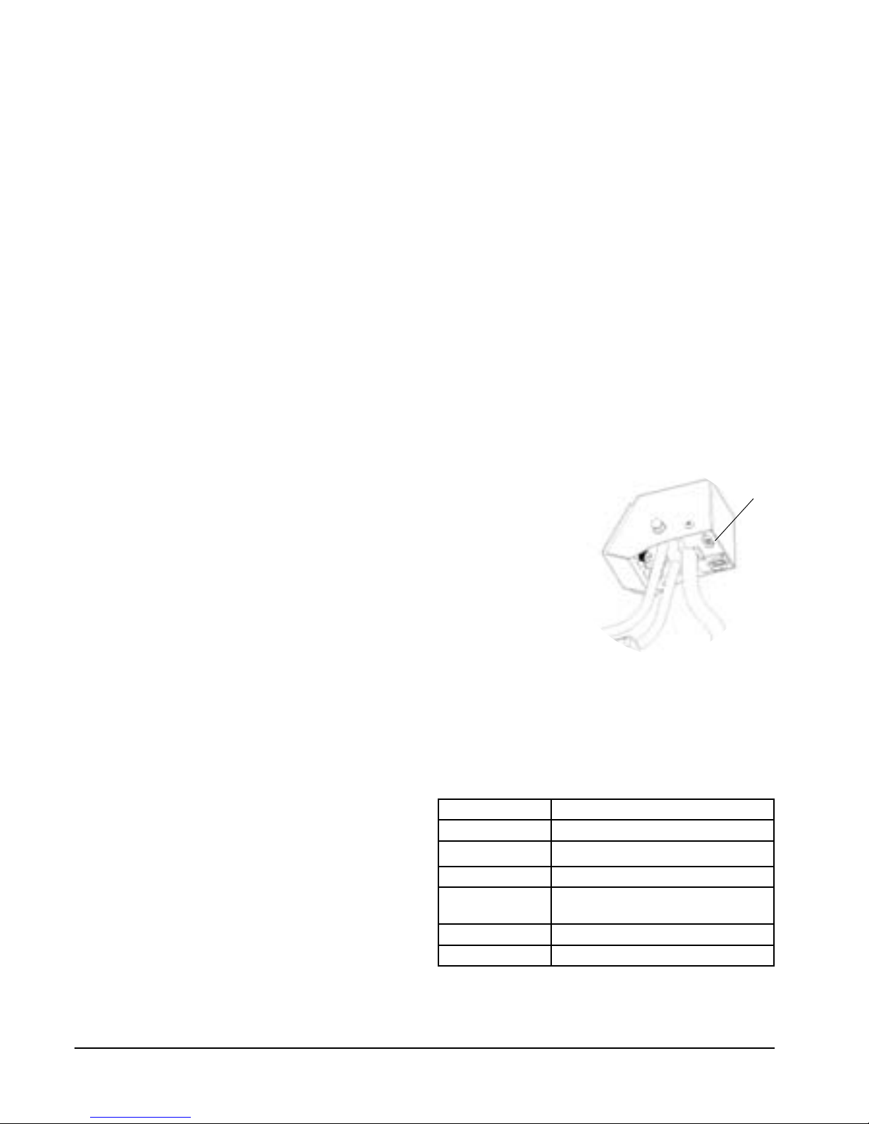
Apply power to the test bike by first connecting the
cable from the power adaptor to the test bike at the
power connector (3) at the right side of the bike, see
Fig: Front cover right. Then plug the power adaptor
into the wall outlet. Turn on the power switch (2) and
a green LED (1) lights up.
The cable from the power adaptor can be locked
with the clamp (4) which is placed below the power
connection.
Perform the electrical calibration as specified in section
"Calibration Electronics”. Test by pedalling the bike.
If the bike is working properly, it is ready for use.
Fig: Front cover right
1) LED (voltage indicator)
2) Power switch
3) Power input
4) Locking for cable (power adaptor)
Page 9
1
LC6 / LC7
9
Power on crank or ywheel
Monark bikes measure the effect of the flywheel, so it
will be a friction of 6-8% if you measure the impact
of the pedals (measure the effect of the crankshaft,
the difference is 4-5 %). These percentages will be
primarily due to friction in the chain, pedals and
bearings.
LC6 / LC7 is designed for fitness tests and is set for
power measurements on the flywheel. The bike can be
set to work with effect in the pedals / crankshaft (the
cycle constant).
Distance meter, miles
Energy kcal
Heart rate bpm
Force Newton (N), kp
Power Watts (W), kpm / min or
VO
2
ml/min/kg
Time min:sec
Weight kilogram (kg), pounds (lbs)
Measured quantities
The following units are normally used. Where multiple
units are specified, the user can select, see the software
documentation.
Control of the bike
LC6 / LC7 is built on a solid framework, a large
well-balanced flywheel, a brake belt and a pendulum
that measures the braking force. The pedals operate
around the brake wheel via a chain, while a stretch
mechanism tightens the brake belt to regulate the
braking force to affect the flywheel. This brake force
is given directly by the pendulum against the scale on
the right side of the bike.
The computer system consists of a main unit (built in
the bike) and a control unit (integrated computer on
the bike, PC, terminal or other external equipment).
The main unit reads pedal speed and braking force
and to determine the test subject's heart rate by a
chest belt, where applicable. In addition, the main
unit activates an actuator, which adjusts the brake belt
tension that regulates the braking force. This brake
force is varied automatically in relation to changes in
pedal speed, so that a constant power is maintained
The bike is as default rpm-independent.
For information about how respective control units
works, see respective sections.
The bike can be controlled externally by PC, terminal
or other external equipment.
Here are instructions for connection and options for
connection to external devices. If advanced technical
documentation / data protocol for system builders or
similar are required, contact Monark Exercise AB.
The control is performed over a serial line using ANSI/
ISO/ASCII format commands. Connector, a 9-pin
D-Sub (male) located below the RPM meter, see Fig:
Connector, is compatible with the RS232 standard.
The bike need not be switched off when connecting
external components, but it is recommended to prevent transmission of incorrect data between devices
over the connection.
Be careful when connecting different types of external
equipment to prevent flash-over and subsequent
injury. The user must ensure that the correct cables are
used, otherwise you risk serious injury or equipment
damage.
Operating Instruction
Fig: Connection
1) RS232 connection
Page 10
3
2
1
LC6 / LC7
10
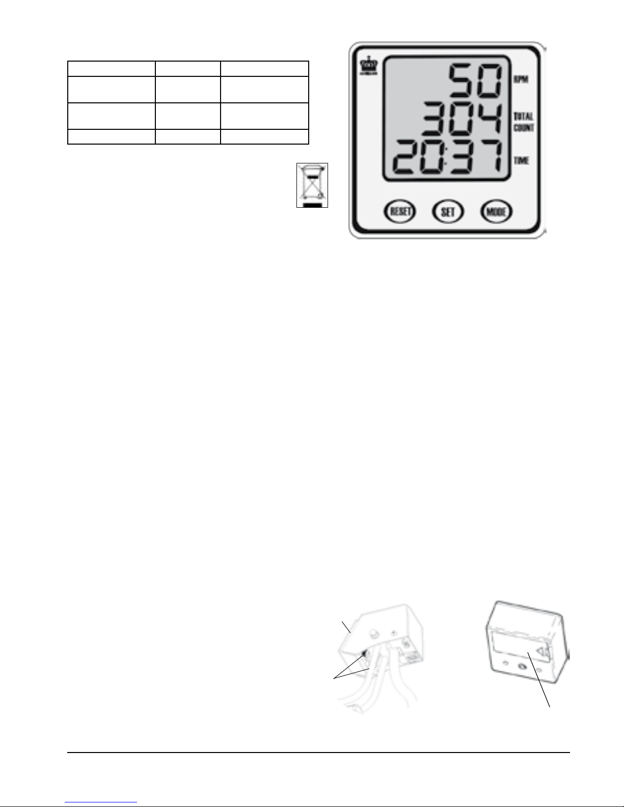
Meter instructions
Keys and functions
MODE key
Use MODE key to shift between the functions to set
TIME and TOTAL COUNT.
SET key
Pressing this key will make it possible to set TIME
and TOTAL COUNT. If you hold down this key for
two seconds you can advance the function value at a
faster rate.
Programming exercise time:
Push the MODE key until TIME flashes. Then use
SET to set the desired time. Each press of SET will
advance time by one minute. When the pedals are
rotated the countdown of time will start automatically
and count down to 0:00 and a beep will be heard for
five seconds.
Programming TOTAL COUNT:
Push the MODE key until TOTAL COUNT flashes.
Then use SET to set the desired value. Each press
of the SET will increase the value by 10. When the
pedals are rotated the countdown of number of turns
automatically start and count down to 0 and a beep
will be heard for five seconds.
RESET key
The RESET key will clear the values for TIME and
TOTAL COUNT individually.
NOTE!
Display will return to normal when not pressed •
any key for five seconds, or trainer is not used.
The meter starts automatically when a key is •
pushed, or if the bike is used and the meter gets
an indication of pedal movement.
Auto shut off function when not pressed any key •
or device not used for four minutes.
Do not expose the meter to direct sunlight or extremely
high temperature. Do not use any dissolvents when
cleaning. Use only dry cloth. For surface disinfection,
see the section "Regular service and maintenance".
Display
Pedal revolution
(RPM)
0 - 250 rev./min.
TOTAL COUNT
9999
Total number of
turns
TIME 0:00-99:59 min:sec
Batteries: 1.5 V x 2, R6 (AA)
Storing temperature: -10º C - +60º C
Operating temperature: 0º C - +50º C
Battery replacement
The batteries can be accessed from the back of the
RPM meter (2). Loosen the meter using the two
screws (1) on the back of the meter, under the meter
bracket.
Open the battery cover (3) and replace the batteries,
see Fig: Battery cover. Replace the meter and secure
it using the two screws.
Fig: Battery replacement
1) Screws
2) RPM meter
3) Battery cover
Page 11

1
5
4
3
2
LC6 / LC7
11
Setting command type (PC or ECG device)
Check that the brake belt is loose around the flywheel,
see Fig: Control loose brake belt. If the brake belt is
tight loosen it by moving the pendulum pointer to
4 kp and the servo releases the brake belt tension.
To be sure that indicator positions are correct, do a
calibration. See section "Calibration".
Turn off the power by turning the power switch 1.
(2), see Fig: Power switch. Disconnect the cable
from any connected external device.
Adjust the scale mechanically so that 0-index on 2.
the scale and indicator are in line. See section
"Zero adjustment of meter panel".
Move the indicator to 6 kp and hold it there.3.
Turn on the power again. The green LED (1) is lit 4.
when power is connected to the bike.
Hold the pendulum pointer at 6 kp until two 5.
beeps are heard.
Move the pendulum pointer to 6.
0 kp = mode for PC, terminal or some PC-
based external device.
1 kp = mode for ECG Siemens Megacart.
2 kp = mode for other ECG devices, alt 1.
3 kp = mode for other ECG devices, alt 2.
7. Keep at the selected position until two signals can
be heard. Then release the pointer to 0. The system
will now restart in the selected mode.
Alt. 1: ECG, Ergoline compatible command set,
requested load value.
Alt. 2: ECG, Ergoline compatible command set,
current load value.
Connection to controller
Fig: Control loose brake belt
Fig: Power switch
1) LED
2) Power switch
3) 6 kp
Page 12

1
LC6 / LC7
12
Connection to PC
To connect a PC to the bike, use a 0-modem cable
(RS232) with 9-pin D-sub connector (female) at both
ends. If no serial port is available on the computer,
use a USB-serial adaptor (included) for connection to
the USB port.
Before installing the Monark Software for your
ergometer, you must take the following steps.
Locate the USB adaptor. 1.
Inside the USB adaptor packaging, there is a mini-2.
CD.
Insert the mini-CD into the CD-ROM drive and 3.
install the driver software. If there is no CD drive
on your computer, driver software is available for
download from the website (http:www.vscom.de/
USB-CD).
Finalize the driver software installation by 4.
inserting the USB adaptor.
Install Monark software (can be downloaded 5.
from our website: www.monarkexercise.se).
Connect the USB Adaptor to the Serial Cable and 6.
proceed with testing.
To control the bike use the computer program "Monark
939 E Analysis Software" which is available for free
download from our website: www.monarkexercise.se.
The software is the same for the models 831 E, 839
E, 939 E and LC6 / LC7. Other external PC software
that are compatible with the bike can also be used.
Terminal Mode PC
A variety of settings can be made from the software.
For more information about this see the software's
help file.
Settings can also be made directly from the PC through
the terminal mode, see the Technichal Manual which
is available from Monark Exercise AB.
Fig: Connection
1) RS232 connection
When power is turned on to the bike it will beep, and
from the number of beeps the command type can be
determined.
Command type 0: A long beep. •
Command type 1: A long beep followed by a •
short beep.
Command type 2: A long beep followed by two •
short beeps.
Command type 3: A long beep followed by three •
short beeps.
What command type (cmd type) is set?
Page 13

1
LC6 / LC7
13
Management of connections
Display with integrated computer on the bike (LC7)
Make sure the power adaptor is connected to the bike
Make sure the USB cable is plugged into the bike
computer and the computer has power (needed if the
computer's internal battery is drained). The computer
can be powered from the bike power adaptor. Set
the bike power switch to "on" and then start the
computer.
Now you can start the computer software in the
computer. If you get a message that the connection
can not be obtained probably the wrong COM port
is registered in the software, see the manual to the
software.
Connecting an external computer (LC7)
Make sure the power adaptor is connected to the bike
Set the bike power switch to "off" and then remove
the USB cable from the bike computer.
NOTE! Det är viktigt att USB-kabeln är urtagen ur
It is important that the USB cable is disconnected from
the bike computer, otherwise there may be a conflict
between the external computer and the display with
integrated computer.
Insert the supplied RS232 cable to the RS232
connector (1) below the RPM meter. At the other end
of the RS232 cable, connect the USB serial adaptor.
Connect the USB connector into an available port
on the external computer. Set the bike power switch
to "on" and then start the software in the external
computer.
If you need a pc software to do exercise tests on the
bike, our software is available for free download from
our website: www.monarkexercise.se.
If you connect an external computer with an RS232
port you can connect the RS232 cable directly into
the serial port and do not need to use the USB serial
adaptor.
Connecting external equipment directly to the RS232
connector (LC6 / LC7)
Make sure the power adaptor is connected to the bike
Set the bike power switch to "off" then remove the
USB cable from the bike computer.
NOTE! NOTE! It is important that the USB cable is
disconnected from the bike computer. Otherwise there
may be a conflict between the external computer and
the display with integrated computer.
Insert the supplied RS232 cable to the RS232
connector below the RPM meter. Connect the other
end of the RS232 cable to the external equipment.
Set the bike power switch to "on" and then start the
external equipment.
Fig: Connection
1) RS232 connection
Page 14
1
2
3
1
LC6 / LC7
14
Checking the pulse function
This bike does not have a meter that shows the heart
rate. However, the heart rate is displayed in the
computer software or other external equipment.
While the patient rests, with the chest belt on, compare
heart rate in the software with the manually taken
pulse. If it does not correspond, check the chest belt
contact area and moisten if necessary the electrode
surfaces with water. Electrodes on the back of the
chest belt. If this fails, call customer service.
The following procedure ensures that the bike works
for daily use.
Check the pulse function, see section.•
Check the brake force, see section.•
Test by pedalling and check that a reasonable •
rpm is obtained - verify by a clock. Feel if the
pedals move smoothly. Listen for unusual sounds.
Remedy if necessary.
Adjust the handlebar and saddle and make sure •
they are securely attached and that the adjustment
is working properly.
Make sure the support legs are in position by •
rocking the bike. Tighten if necessary.
If something unusual is found during the daily
inspection that you cannot resolve, please call
customer service.
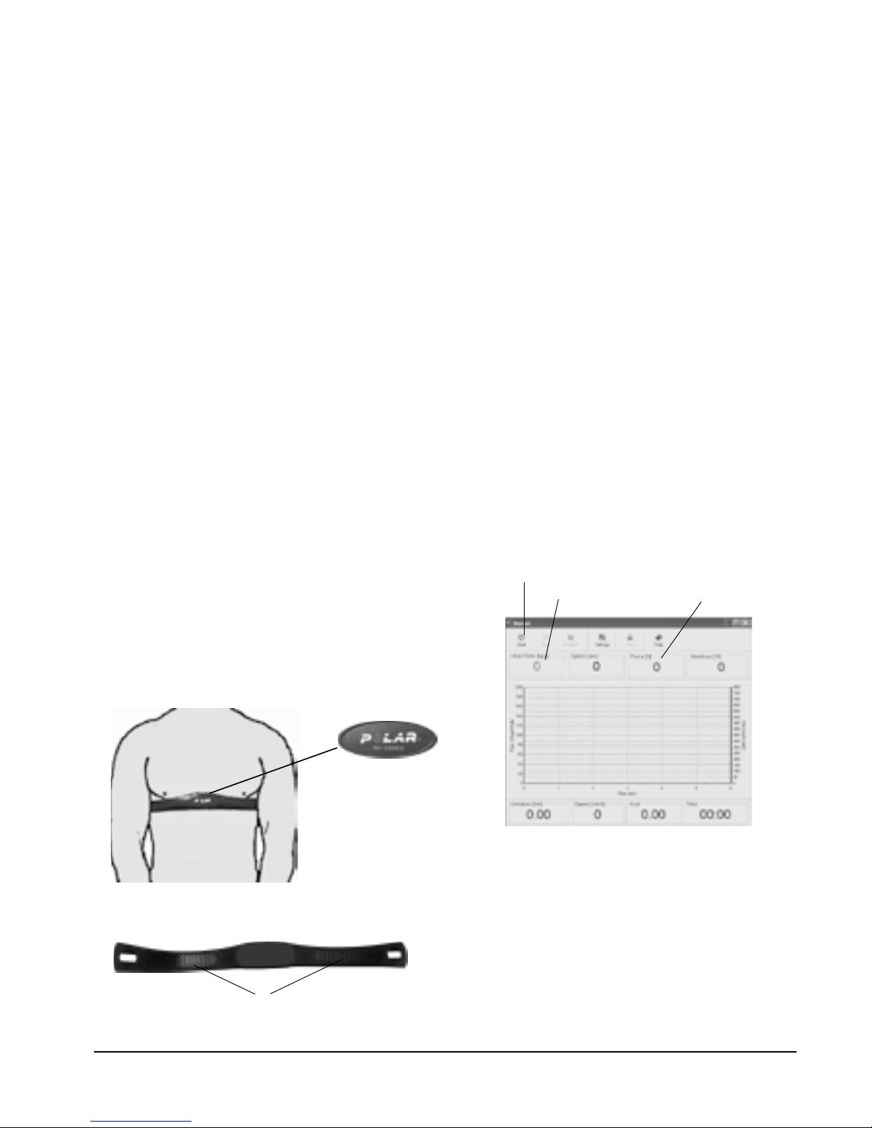
Fig: Placement of the chest belt
Validation
Validation of force
Start the PC software (it is available for free download
from our web site: www.monarkexercise.se) and
select a test programme from the menu "Test". In the
dialogue box that opens is a box showing the braking
force in Newton, see Fig: Force and HR display. You
do not have to press "Start" (1) to get the heart rate
showed (2), but you must press "Start" to show the
force (3).
With the pendulum pointer at 0, the display should 1.
read "00N".
Move the pendulum pointer to 4 kp and the display 2.
should now show "39N".
If the braking force is not displayed correctly, an
electronic calibration must be done. See section
"Calibration electronics".
NOTE!
After this verification, the brake belt will be loose,
which means that it takes about 15 seconds before the
regulating device has tense the brake belt to normal
again (5 N).
Fig: Force and HR display
1) Start
2) Heart rate display
3) Force in software (manual test)
Fig: Electrodes on the back of the chest belt (1)
Page 15

4 kg
1
3
4
2
1
2
3
1
2
3
LC6 / LC7
15
Zero adjustment of scale
Check that 0-index (3) on the scale (2) is in line with
the pendulum pointer when the bike is at a stand
still and the brake belt is loose. If not, an adjustment
must be done. Loosen the screw and adjust the scale.
Tighten the screw (1) after adjustment. See Fig:
Adjustment scale.
Calibration
All LC6 / LC7 are calibrated in the factory, but a
calibration of the pendulum can still be done to verify
this. If so, please do the following.
Open the front cover. Check that the brake belt (3) is
loose. If not, move the pendulum to 4 kp and hold it
there a while to loosen it. Unhook the brake belt from
the spring. Check that scale 0-index is in line with
the pointer. Adjust if necessary, see section "Zero
adjustment of scale".
Calibration weight 4 kg (Art. No: 9000-211) is
hooked on the spring.
NOTE!
The flywheel must be completely stopped before the
weight is hung on!
This weight (4 kg) can, when properly adjusted, be
read at the corresponding point on the scale. If there is
a deviation, adjust the pointer to the correct position
by adjusting the weight (2) inside the pendulum. To
change the adjustment weight loosen the adjustment
screw (1). If the pointer shows too low, the internal
weight must be moved upwards. If the pointer shows
too high, the adjustment weight is moved down.
This process is repeated until pointer is in the correct
position. Hook the brake belt in the spring and close
the front cover.
Check the calibration of the pendulum weight once a
year or when needed.
Fig: Calibration
1) Kp-scale
2) Pointer
3) Spring
4) Calibration weight 4 kg
Fig: Pendulum
1) Adjustment screw
2) Adjustment weight
3) Brake belt
Fig: Adjusting scale
1) Screw
2) Scale (Kp-scale)
3) 0-index
Page 16

LC6 / LC7
16
The following steps show how electronics are
calibrated against the pendulum.
Open the front cover. 1.
Check that the brake belt is loose on the flywheel, 2.
see Fig: Control loose brake belt. If not, move
the pendulum pointer to 4 kp and hold it there
for a few seconds. Move the pendulum pointer
to 0 again, and check again that the brake belt is
loose.
Adjust the scale, see "Zero adjustment of scale," 3.
so that the pendulum pointer is pointing at the
0-index of the scale, see Fig: Zero position.
Turn off the power to the bike and move the 4.
pendulum pointer to 4 kp, as shown in Fig: 4 kp.
Hold the pendulum pointer at 4 kp and turn the 5.
power on the bike again and wait for a beep.
Move the pendulum pointer to 0, see Fig: 0 kp.
Wait for a beep.
Move the pendulum pointer to 2 kp, see 6. Fig: 2 kp.
Wait for a beep.
Move the pendulum pointer to 4 kp, see 7. Fig: 4 kp.
Wait for a beep.
Move the pendulum pointer to 6 kp, see 8. Fig:
6 kp. Wait for two beeps. Move the pendulum to
0 again.
The calibration is complete. Close the front cover.
Electronic calibration - with the pendulum
Calibration electronics
Usually it is not necessary to recalibrate the cycle
electronically, but it should be done after each service,
change of electronic part, movement, if you adjusted
the 0-index, or after you have programmed the
"Reset" by default settings.
The calibration coefficient calculated by the computer
is stored in main memory. No matter when the power
is turned on, the last stored calibration will be placed
in main memory. New calibration automatically
replaces the old.
A check of the electronic calibration can be done in
the computer programme, see section "Validation of
force".
NOTE!
The pendulum must be kept still at the different
positions. This is done by pressing down the pointer
into the groove on the scale at each kp value.
Calibration
LC6 / LC7 has a mechanical brake and pendulum
weight, making performance validation a simple
procedure. Calibration is necessary so that the
electronic and the mechanical parts of the cycle
conform. The work carried out on the bike is a
result of the braking force (pendulum mode) and the
number of pedal revolutions (= distance). The effect
is then counted out by dividing the work done by the
time it took to accomplish it. Validation includes both
mechanical and electronic procedures. For detailed
information, see the computer programme's user
manual. If the bike fails to pass any section of the
validation, proceed to the calibration and/or service
menu.
After any repair or service, a "Daily Check" should
be done.
It is also possible to calibrate from the software. See
the menu "Monark Ergomedic" - Check calibration..." in the computer software.
Page 17

LC6 / LC7
17
Fig: Control loose brake belt
Fig: Zero position
Fig: 2 kp.
Fig: 4 kp.
Fig: 6 kp.
Fig: 0 kp.
Page 18

LC6 / LC7
18
Testing with LC6 / LC7
The versatility of the LC6 / LC7 enables it to be utilized
in a variety of testing environments. The precision
and reproducibility of the test values obtained with
the bike, along with the uncomplicated way to set up
the tests, means the bike can be used in clinical work
tests, in occupational health services for the fitness
tests as well as fitness centers, schools, sports clubs
and the like.
In general, one should note that stresses on the tested
person can become quite severe, whether in a clinical
work test or a simple fitness test in physical activity
contexts. As a precaution, it may be advisable, prior
to beginning an exercise protocol, that each subject
consults with a physician.
Before testing, the operator should review the entire
protocol operation with the test person, explaining
the work which will be required and the duration of
the procedure. One should also agree on how the test
person shall give signs of any fatigue, chest pain or
other abnormal physical reactions.
The test person should not engage in heavy physical
activity for several hours prior to testing to establish
maximum oxygen consumption. In addition, all
testing and exercise protocols should be performed
a reasonable time after meals. The test person should
also refrain from smoking within an hour of the
testing period.
The tested person shall also have the appropriate
clothing for a work test. Training suit or loosefitting clothing is best. More detailed instructions
are rarely needed, regarding the ride, but it may
still be appropriate for the test leader to give some
advice on pedalling, saddle height and position of
the handlebars. It should be comfortable to ride. The
appropriate height of the saddle is when the knee is
slightly bent when the sole of the foot is centred over
the pedal axle with the pedal in the bottom position.
Let the test subject try to ride with low workload and
see how it feels to hold a steady rpm.
Finally, the chest belt shall be put on, see Fig: Placement
heart rate belt in section "Heart Rate (telemetry)" for
correct placement. Check for a minute that a proper
heart rate is displayed. The baseline heart rate may
also be of assistance in determining the nervousness
of the test subject. It may be appropriate to let the test
person rest long enough before the test so a more or
less stable resting heart rate can be read.
Power calculation
1 rpm = that a point on the flywheel moves 6 meters
per minute.
50 rpm = 300 m
2 kp force makes 2 x 300 = 600 kpm/min
100 rpm= 600 m
1 kp force makes 1 x 600 = 600 kpm/min
Exact calculation:
Watts = rpm x kp x 0.98065
"Rule of thumb" calculation:
Watts = rpm x kp
(2% error, but may be good enough in many cases)
Page 19

1
LC6 / LC7
19
Test person enforcement
The bike performs automated tests virtually by itself,
requiring minimal intervention by the test operator.
This allows the operator to pay careful attention to
the test person without distraction. The response to
the exercise protocol can be accurately estimated and
appropriate action taken to assist the test person, if
necessary. Some programmes have sections where
the test person may develop significant physical
activity. The effect on the test person should not be
underestimated.
During the test it is important to observe the test
person's appearance and heart rate. The testing should
be stopped immediately if the test person reports chest
pain, difficulty in breathing, etc. A system of prompt
medical attention should be set up prior to testing, in
case of emergency.
The test person may also have difficulty in keeping a
steady pedalling speed. This is of minor importance
(except in cases where the program assumes a constant
braking force, since the effect is automatically adjusted
to the correct value as long as the pedal speed is at least
35 revolutions / min (rpm)). However, it is important
to consider what each test documentation says about
the pedal speed.
Heart Rate (telemetry)
A person's heart rate can be measured with a chest
belt that senses the electronic output of the heart. The
chest belt is standard equipment.
The bike does not have a meter that shows the heart
rate, however, the HR is displayed in the computer
programme or in other externally connected devices.
Fuss-free HR measurement requires that the belt is
correctly placed. When it is correctly fitted the logo
on the belt will be central and readable, outward
and upright, by another person. Before putting on
the belt, clean the skin where the belt is to be placed.
The chest belt should be secured at a comfortable
tension around the mid section, just below the breast
muscle, see Fig: Placement of the chest belt. Moisten
the electrodes before use, see Fig: Electrodes on the
back of the chest belt. To make contact with the HR
receiver on the bike, the distance should not be more
than 100 cm / 39 1/3". It is especially important when
first used to identify the chest belt with the sensor, by
standing close to get the HR (maximum 60 cm). This
relates especially to the Polar heart rate belt.
NOTE! Electromagnetic waves can interfere with the
telemetry system. Cellular phones are not allowed to
be used near the bike during test.
In case of problems, turn off WiFi, Bluetooth and
similar on computers nearby (including the display
with integrated computer on LC7).
Fig: Placement of the chest belt
Fig: Electrodes on the back of the chest belt (1)
Page 20

LC6 / LC7
20
Fitness Rating Index - Males
Maximum Oxygen Consumption ml/kg/min
Fitness Rating Index - Females
Maximum Oxygen Consumption ml/kg/min
Rating Rating
-36 yrs 36-45
yrs
45- yrs -36 yrs 36-45
yrs
45- yrs
Excellent 54 53 43 Excellent 55 49 46
Good 49 45 38 Good 45 43 38
Above aver-
age
46 39 34 Above aver-
age
39 37 32
Average 36 33 30 Average 34 33 27
Below aver-
age
32 29 27 Below aver-
age
30 29 24
Fair 28 25 24 Fair 26 26 20
Poor 24 23 20 Poor 20 22 18
See also table 7 in “ Work tests with the Bicycle Ergometer“ by P O Astrand.
Reviewing results
The maximum oxygen uptake is a
standard measure of the condition of the heart- and
lung-functions. Dependent on the linear relationship
between work and oxygen uptake and between work
and heart rate, the heart rate response to work may
be used to estimate the oxygen consumption. If the
maximum heart rate is considered, the maximum
oxygen consumption may be determined.
The YMCA and Åstrand protocols estimate
the maximum oxygen consumption, based on a
submaximal workload while all others report the
oxygen consumption required by the final workload.
The Bruce and Naughton protocols require that the
test subject exercise at a workload level for a minimum
of one minute to establish the oxygen consumption.
If less than one minute is observed, the previous
workload value is used.
The estimated maximum oxygen consumption
derived from some of the ergometer tests is subject
to the error of the “age related predicted maximum
heart rate“. Although there is a definite and linear
relationship between work and oxygen uptake, there
are some differences in actual oxygen uptake based
on individual work efficiency. Test persons who are
less familiar with bike exercise and those individuals
who are less fit, are more likely be less efficient than
those who ride bikes frequently.
It should be noted that these results are estimates or
predictions of maximal response and have a greater
chance of being in error than if the individual were
tested to their actual maximum value. Interpretation
should therefore be made more carefully with an
understanding of the possibility of errors in the
methodology.
A relative fitness index can be obtained from the
following tables:
Page 21

LC6 / LC7
21
Symptoms Probable Cause / Corrective Action
LED does not light up No current in the outlet. Check the fuses. •
Power switch turned off bike / main unit. •
Check cables and connections. •
Right AC adaptor? Check that the transformer information (voltage, current, po-•
larity, AC / DC) in section "Facts" complies with the transformer which is used.
No connection to PC Check cables (connections and type). •
Right COM-port (PC software or similar). •
Drivers missing when using the USB-serial adaptor. (CD with drivers is included •
with the USB-serial adaptor).
Right "cmd type", see section "Connection to controller". •
No workload Pendulum stuck. Contact service centre for action / replacement. •
Check that the pedal speed is higher than 35 rpm. No workload is put on if the •
actual pedal speed is lower than 35 rpm. See computer software menu - ’Monark
Ergomedic’ - ’Service program...’ - ’Service setup...’ - ’Pedal measurement’. The
default setting is 30 rpm but can be adjusted to the desired value.
Check calibration.•
Check that brake belt is hooked in the spring.•
No heart rate Check that the battery is alright in the chest belt, moisten your thumbs and click •
on the electrodes, a low clicking sound will be heard at the battery cover, alternatively that the heart rate is displayed in the computer software.
Make sure the belt fits correctly on the test person, see • Fig: Placement of chest belt
in section "Heart Rate (telemetry)", and that the strap is sufficiently tightened.
Moisten the electrodes, in severe cases it may be necessary to use gel alternative,
one drop of dish washing liquid mixed in water. Pulse signal strength varies from
person to person. Try the belt with a person known to have a good pulse wearing
a chest belt.
Check for loose cables or jack if you have a plug-in receiver. Use another HR re-•
ceiver (HR watch or test bike monitor) to check the chest belt.
Check that it is the correct receiver and that it is in the correct place. If it have a •
round Polar logo, the logo should be readable.
Uneven heart rate Use an external unit, for example a HR watch, to check if it also indicates an ir-•
regular pulse. If this is the case, there is probably disturbance in the room. The
disturbance may be electronic fields from power cables, elevators, lamps etc. or
other electronic devices which are too close (eg. cell phones). Move the bike to
a different location in the room or change rooms. If an irregular HR remains it
should be checked manually. If the HR remains irregular at work the person's
health should be examined.
No rpm reading Check cable.•
Unable to calibrate force The potentiometer shaft is not attached to the pendulum shaft, tighten the screw. •
The potentiometer is misadjusted. See the computer software menu - ’Monark •
Ergomedic’ - ’Service program...’ - ’Potentiometer’ and follow the instructions
that appear on the screen. Then calibrate the electronics again.
There is a click noise when pedal-
ling (increases with the weight)
The pedals are not tight. Tighten them or change pedals. •
The crank is loose. Check, tighten. •
The base bearing is loose. Contact your dealer for service. •
Scratching sound is heard when
pedalling
Check that the carriage block is taken off and that nothing is against the crank, •
chain, or wheel except the brake belt.
There’s a click noise and a squeak
noise when pedalling
Loosen the chain. •
Troubleshooting guide
Page 22

LC6 / LC7
22
Operation interferences
It is normally considered that about 70 % of all shutdowns on small computers are caused by mains interferences,
i.e. at short over voltage. These interferences can often be caused by different machinery, which is started or
stopped. The processor in the computer is then reacting incorrectly or is not working at all. The problems can
be solved by means of a mains interference protector, which is connected between the wall outlet and the AC
adaptor. .
Error message
Message Cause
"Test is aborted" An automatic test program has been stopped before it is
ready, or with values that are outside the tables so that no
result can be calculated. No test results can be obtained.
Page 23

LC6 / LC7
23
Where to obtain additional information
The user may require more information concerning several areas of the ergometer usage. This manual was
intended to instruct the reader primarily in the operation of the ergometer. References are made to related topics
in the discussions concerning the testing procedures and the protocol operation sections. The following literature
may provide some greater insight to ergometer-based testing without confusing the reader with technical medical
terms.
Åstrand P-O, ”Ergometri - konditionsprov”, Monark, Sverige. •
Golding L. A, Myers C. R, Sinning W. E, Y´s way to physical fitness“, YMCA of the USA, Rosemont, IL, •
1982
For more technical details, see the section entitled “Reference“.
References
Astrand I, ”Aerobic work capacity in men and women with special reference to age”, Acta Physiol Scand. 1.
49 (suppl. 169), 1960
Åstrand P-O, ”Experimental studies of physical working capacity in relation to sex and age”, Munksgaard, 2.
Köpenhamn, 1952.
Åstrand P-O, Rodahl K, ”Textbook of Work Physiology”, McGraw-Hill, New York, 1970.3.
Bruce RA, Kusumi F, Hosmer D, ”Maximal oxygen intake and nomographic assessment of functional aero-4.
bic impairment in cardiovascular disease”, Am Heart J 85:546-562,1973
Naughton J, ”Exercise Testing and Exercise Training in Coronary Heart Disease”, Academic Press, New 5.
York, 1973.
Golding LA. Myers CR, Sinning WE, ”Y´s way to physical fitness” YMCA of the USA, Rosemont, IL, 6.
1982
Wilson PK, Bell CW, Norton AC, ”Rehabilitation of the heart and lungs”, Beckman instruments, 19807.
Åstrand P-O, ”Ergometri - konditionsprov”, Monark, Sverige8.
Page 24

Service check and Maintenance
It is important to carry out a regular service on your
ergometer, to ensure it is kept in good condition.
Always keep the bike clean and well lubricated.
Service action:
We recommend isopropyl alcohol to disinfect the •
surface of the bike. Use a damp but not wet cloth to
clean the surface you wish to disinfect.
Surface treatment with a rust inhibitor, especially •
when the bike is clean and the surfaces are dry This
is done to protect the chrome and zinc parts as well
as the painted parts (4 times per year).
Check now and then that both pedals are firmly •
tightened. If not the threading in the pedal arms
will be damaged. When the Ergometer is new it
is important to tighten the pedals after 5 hours of
pedalling (4 times per year).
Check that the pedal crank is secure to the crank •
axle (4 times per year).
Be sure that the pedals are moving smoothly, and •
that the pedal axle is clear of dirt and fibres (4 times
per year).
When cleaning and lubricating be sure to check that •
all screws and nuts are properly tightened (twice a
year).
Check that the chain is snug and there is no play in •
the pedal crank (twice a year).
Check that pedals, chain and freewheel sprocket are •
lubricated (twice a year).
Be sure that the brake belt does not show significant •
signs of wear (twice a year).
Check that the handlebars and seat adjustment •
screws are lubricated (2 times per year).
Be sure that all moving parts, crank and flywheel •
are working normally and that no abnormal play
or sound exists. Play in bearings causes fast wearing
and with that follows a highly reduced lifetime.
Check that the flywheel is placed in the center and •
with plane rotation.
Grind the brake belt contact surface, see section •
"Brake belt contact surface" (once a year).
Service
Warning
Make sure the voltage indicated on the appliance
corresponds to the local mains voltage before making
connections.
Note that the text about service and maintenance is
universal and that all parts may not be relevant to
your bike.
Warranty
EU countries - Private use
If you are a consumer living in the EU you will have
a minimum level of protection against defects in
accordance with EC Directive 1999/44/EC. In short,
the directive states that your Monark dealer will be
liable for any defects, which existed at the time of
delivery. In case of defects, you will be entitled to have
the defect remedied within a reasonable time, free of
charge, by repair or replacement.
EU countries - Professional use
Monark Exercise products and parts are guaranteed
against defects in materials and workmanship for a
period of one year from the initial date of purchase
of the unit. In the event of a defect in material or
workmanship during that period, Monark Exercise
will repair or replace the product. Monark Exercise will
not, however, refund costs for labour or shipping.
Other countries
Monark Exercise products and parts are guaranteed
against defects in materials and workmanship for a
period of one year from the initial date of purchase
of the unit. In the event of a defect in material or
workmanship during that period above, Monark
Exercise will repair or replace (at its option) the
product. Monark Exercise will not, however, refund
costs for labour or shipping.
LC6 / LC7
24
Page 25

If the meter is battery-operated, the batteries are in a
separate package at delivery. If the storing time has
been long the battery power can be too low to make
the computer act correctly. Batteries must then be
changed.
Flywheel bearing
The flywheel bearing is long-term greased and requires no supplementary lubrication. If a problem
arises, please contact your Monark dealer.
Crank bearing
The crank bearing is greased and normally requires
no supplementary lubrication. If a problem arises,
please contact your Monark dealer.
Transportation
During transport the brake cord should be tightened
to prevent it from falling off the flywheel.
Replacement of brake belt
To replace the brake belt remove covers if necessary.
Make sure that the belt is loose.
Pendulum bike with engine:
To loosen the brake belt on pendulum bikes with
engine, connect power to the unit and raise the
pendulum to 4 kp. Hold it there until brake belt is
loose. Please note how the belt is assembled. Remove
it from the bike. Attach the new brake belt and
assemble the bike in reverse order.
Weight basket bike:
To loosen the brake cord on cycles with a weight
basket set the basket to its upper position. Loosen the
lock washer that is holding the cord and remove it
from the tension center. Loosen or cut off the knot on
the other end of the cord and then remove the whole
cord from the bike. When assembling a new brake
cord, first enter one end into the hole in the tension
center, and tie a knot and let the knot fall into the
bigger part of the hole. Lock the end of the cord with
the lock washer.
Brake belt contact surface
Deposits of dirt on the brake belt and on the contact
surface may cause the unit to operate unevenly and will
also wear down the brake belt. The contact surface of
the flywheel should be smoothed with fine sandpaper
and any dust removed with a clean dry cloth.
Remove any potential covers and all workload on
the brake belt and then remove it. Grind with a fine
sand paper. Grinding is easier to perform if a second
individual cautiously and carefully pedals the cycle.
Irregularities on the brake belt contact surface are
removed by means of a fine sand paper or an abrasive
cloth. Otherwise unnecessary wear on the brake belt
may occur and the unit can become noisy.
Always keep the brake belt contact surface clean and
dry. No lubricant should be used. We recommend
replacing the brake belt when cleaning the contact
surface. In regard to assembly and adjustment of the
brake belt, see ”Replacement of brake belt”.
Manual pendulum bike / exercise bike:
To loosen the brake belt on the bike remove all tension.
Please note how the belt is assembled. Remove it from
the bike. Attach the new brake belt and assemble the
bike in reverse order.
NOTE!
When replacing the brake belt it is recommended
to clean the brake surface. See ”Brake belt contact
surface”.
Batteries
LC6 / LC7
25
Fig: Brake belt contact surface
Page 26

Chain 1/2“ x 1/8“
Check the lubrication and tension of the chain at
regular intervals. In the middle of its free length the
chain should have a minimum play (3) of 10 mm (1/4
inch). See Fig: Chain adjustments. When the play in
the chain is about 20 mm (3/4 inch) the chain must
be tightened. Otherwise it will cause abnormal wear
of the chain and sprockets. Therefore it is always
recommended to keep the chain play as small as
possible. Loosen the hub nut (2) on both sides and
tense the chain with the chain adjuster (1) when
needed.
When the chain has become so long that it can no
longer be tightened with the chain adjusters it is worn
out and should be replaced with a new one.
To adjust or replace the chain, remove covers if
required.
To adjust the chain the hub nuts (2) should be
loosened. Loosening or tightening the nuts on the
chain adjusters (1) will then move the hub and axle
forward or backward. Then tighten the nuts on the
hub axle again. See Fig: Chain adjustments.
To replace the chain, loosen the chain adjusters as
much as possible. Dismantle the chain lock (6) and
remove the chain. Use pliers to both release the lock
washer and mount it again (4). Put on a new chain
and assemble the chain lock. The spring of the chain
lock should be assembled with the closed end in the
movement direction (5) of the chain. See Fig: Chain
replacement.
NOTE!
At assembly the flywheel has to be parallell with
the centerline of the frame. Otherwise the chain and
sprockets make a lot of noise and wear out rapidly.
kuggtoppar.
Then assemble the removed parts as above but in
reverse order.
4
6
5
3
2
1
LC6 / LC7
26
Fig: Chain replacement
4) Lock spring
5) Movement direction
6) Chain lock
Fig: Chain adjustments
1) Chain adjuster
2) Axle nut
3) Chain play
Page 27

Freewheel sprocket
When replacing the freewheel sprocket remove frame
covers if necessary. Remove the chain according to
section ”Chain 1/2” x 1/8””.
Loosen the axle nuts and lift off the flywheel. Remove
the axle nut, washer, chain adjuster and spacer on
the freewheel side. Replace sprocket-adaptor and
assemble the new parts in reverse order according to
the above.
NOTE! Do not tighten the axle nut completely. It
must be possible to loosen the adaptor-sprocket half
a turn.
The sprocket should be lubricated with a few drops of
oil once a year. Tilt the cycle to make it easier for the
oil to reach the bearing. See Fig: Lubrication.
LC6 / LC7
27
Fig: Lubrication
Fig: Hub assembly
Page 28

1
7
15
16
12
18
19
17
14
13
8
9
10
20
6
21
22
23
26
27
28
31
29
27
5
4
3
2
11
26
25
24
LC7
31
32
LC6
LC7
30
LC6 / LC7
28
Spare parts list
Page 29

LC6 / LC7
29
Fig: Chest belt
Pos. Qty. Art. No. Description Pos. Qty. Art. No. Description
1 1 9300-147 Saddle, racer with adaptor 1 9310-29 Handlebar with stem and
clamp, complete
1 C7100535 -Saddle Exeo Road white 21 1 9310-92 -Handlebar stem
1 9336-42 -Adaptor to race-/sport saddle 22 1 9310-24 -Handlebar clamp
2 1 9310-28 Sledge, complete 23 1
C2205419-120 -Reparto corse stem 120 mm Al
3 1 9311-24
-Locking handle black M10x32,
complete
24 1 C2305771-42 -Reparto corse handlebar
1 9310-281 -T-slot nut M10 1 C2600079 -Handlebar tape EVO black
4 1 9310-30 Seatpost with ruler 25 1 9311-74
-Locking handle black M10x80,
complete
5 8322-70 Pedal combi SPD/Look 1 9310-281 -T-slot nut M10L
6 1 9301-3 Support tube rear, complete 26 2 9310-27 Piston locking, complete
2 9328-51 -Plastic cap 2 9100-289 -Locking handle blue M10x50,
complete
2 9328-26 -Rubber foot with screw M8 27 2 9328-1315 Bushing with hole
7 1 9301-4
Support tube front, complete
1 9339-89 Chest belt Polar Wear-link
2 9328-51 -Plastic cap
2 9328-26 -Rubber foot with screw M8
2 9328-37 -Transport wheel, complete
8 1 9338-26 LED lamp LC7 9310-35-7 LC7 Display bracket, complete
9 1 9310-72 Switch (on / off) 28 1 9310-33 -Computer holder LC7
10 1 8243-7 Holder for cable 29 1 9310-32 -Locking strap for computer
11 1 9310-13
Pendulum scale 7 kp, complete
31 1 9371-68 -Digital meter
1 9310-152 -Scale 9000-103 -Screw M5x12
1 9000-103 -Screw M5x12 30 1 9310-96 Holder for Lenovo LC7
12 1 9310-595
Side cover rear, right (outer
chain guard)
1 9339-66 Power adaptor, export
13 1 9310-620 Side cover front, right, with
recess for pendulum scale
1 9339-67 Power adaptor, SE
14 1 9310-20 Front cover LC6 9310-35-6 LC6 Display bracket, complete
15 1 9310-71 Lock to front cover 32 1 9310-77 -Document holder LC6
16 1 9310-630 Side cover front, left 31 1 9371-68 -Digital meter
17 1 9310-89 Bracket plate pulse receiver 2 9000-103 -Screw M5x12
18 1 9338-21
Pulse receiver Polar, complete
1 9339-66 Power adaptor, export
19 1 9310-605 Side cover rear, left 1 9339-67 Power adaptor, SE
20 1 9000-103 -Screw M5x12
Page 30
11
8
7
6
10
4
5
3
2
1
9
14
17
15 16
13
12
LC6 / LC7
30
Pos. Qty. Art. No. Description Pos. Qty. Art. No. Description
1 1 9310-45 Pendulum 7 kp, complete 9 1 9338-24 Electronic box
1 9310-43 -Pointer 10 1 9300-3 Flywheel, complete
1 9326-88 -Spring 11 1 9300-24 -Flywheel suspension, complete
2 1 9100-26 Tension cylinder 12 1 9310-57 Motor, complete
3 2 9300-99 Stop 13 1 9310-88 Potentiometer with data card and
cable
4 1 9310-94 Brake belt, complete 14 1 9300-478 Crank set 52 T with 13 magnets
5 1 9310-48 Locking strap for electronic
box
15 1 9300-480 Bottom bracket 68/110 mm
6 1 9310-64 Strut with bracket 16 1 9310-90 Inner chain guard
7 1 9310-65 Strut without bracket 17 1 9310-118 Chain 9300, 120 L, with chain lock
8 1 9310-46 Frame for electronic box
Page 31

...........................................................................................................................................................................
...........................................................................................................................................................................
...........................................................................................................................................................................
...........................................................................................................................................................................
...........................................................................................................................................................................
...........................................................................................................................................................................
...........................................................................................................................................................................
...........................................................................................................................................................................
...........................................................................................................................................................................
...........................................................................................................................................................................
...........................................................................................................................................................................
...........................................................................................................................................................................
...........................................................................................................................................................................
...........................................................................................................................................................................
...........................................................................................................................................................................
...........................................................................................................................................................................
...........................................................................................................................................................................
...........................................................................................................................................................................
...........................................................................................................................................................................
...........................................................................................................................................................................
...........................................................................................................................................................................
...........................................................................................................................................................................
...........................................................................................................................................................................
...........................................................................................................................................................................
...........................................................................................................................................................................
...........................................................................................................................................................................
...........................................................................................................................................................................
...........................................................................................................................................................................
...........................................................................................................................................................................
...........................................................................................................................................................................
LC6 / LC7
31
Notes
Page 32

KROONS VÄG 1, SE-780 50 VANSBRO, SWEDEN | WWW.MONARKEXERCISE.SE | TEL: +46(0)281 59 49 40 | FAX: +46(0)281 719 81
Version 1402
Art. No: 7950-359
 Loading...