

Page 1
EN
Manual for
LC4
LC4r
Page 2

Page 3

Monark Exercise AB ��������������������������������������������������������������������������������4
Product Information ��������������������������������������������������������������������������������6
Facts........................................................................................................... 6
PC software ................................................................................................ 6
Serial number ............................................................................................. 6
Calories ...................................................................................................... 6
Initial operation ........................................................................................... 6
Power on crank or ywheel ........................................................................ 6
Cycle adjustments �����������������������������������������������������������������������������������8
Adjustments of the bike .............................................................................. 8
Cycle adjustments ...................................................................................... 8
Validation .................................................................................................... 8
Pulse function ������������������������������������������������������������������������������������������9
Pulse standard (chest belts) ....................................................................... 9
Pairing display and chest belt..................................................................... 9
Display Description �������������������������������������������������������������������������������10
Sleep mode .............................................................................................. 10
Personal settings ...................................................................................... 11
Alternative power / force display .............................................................. 11
User settings ������������������������������������������������������������������������������������������12
Steady State HR ...................................................................................... 13
Calibration ����������������������������������������������������������������������������������������������14
Calibration electronics .............................................................................. 14
Manual motor control................................................................................ 14
Calibration ................................................................................................ 16
Zero adjustment of scale .......................................................................... 16
Current potentiometer value ..................................................................... 17
Training ��������������������������������������������������������������������������������������������������18
METS ������������������������������������������������������������������������������������������������������19
Astrand ���������������������������������������������������������������������������������������������������20
YMCA ������������������������������������������������������������������������������������������������������22
Increment �����������������������������������������������������������������������������������������������24
PWC �������������������������������������������������������������������������������������������������������26
Testing using LC4 ���������������������������������������������������������������������������������28
Test person enforcement .......................................................................... 28
Reviewing results ..................................................................................... 29
Troubleshooting guide ��������������������������������������������������������������������������30
Service ����������������������������������������������������������������������������������������������������32
Warranty ................................................................................................... 32
Service check and Maintenance .............................................................. 32
Batteries ................................................................................................... 33
Flywheel bearing ...................................................................................... 33
Crank bearing ........................................................................................... 33
Transportation .......................................................................................... 33
Replacement of brake belt ....................................................................... 33
Brake belt contact surface ........................................................................ 33
Chain 1/2“ x 1/8“ ....................................................................................... 34
Freewheel sprocket .................................................................................. 35
Spare parts list ��������������������������������������������������������������������������������������36
2014 MONARK EXERCISE AB, Vansbro, Sweden
Contents
Important
Read the manual carefully before using the cycle and save it for future
use.
Page 4

LC4 / LC4r
4
Monark Exercise AB
Monark has 100 years’ experience of bicycle production. The Monark tradition has yielded
know-how, experience, and a real feel for the product and quality. Since the early 1900s,
Monark’s cycles have been living proof of precision, reliability, strength and service. Those
are the reasons why we are now the world leader in cycle ergometers and the market leader
in Scandinavia in transport cycles.
We manufacture, develop and market ergometers and exercise bikes, transport bikes and
specialized bicycles. Our largest customer groups are within health care, sports medicine,
public authorities, industry and postal services.
For more information: http://www.monarkexercise.se
Page 5
LC4 / LC4r
5
Thank you for choosing a test cycle from Monark!
Ideal position is important for a performance to reach its maximum and increases the potential for a
perfect performance. The new setting options, along with an upgraded workload adjustment, make
Monark's renowned bike even better.
LC4 has a brand new frame that is adjustable in all directions•
LC4's new frame also means the Q-factor can be reduced, which increases the opportunities for •
a better workout experience
LC4 gives the condition, the rest is up to the rider•
LC4 is also prepared for additional equipment - channels behind the covers make it easy to install •
different equipment for different needs
LC4 is a great bike as it is, with additional equipment, it can be even better•
LC4 can be calibrated, both mechanically and electronically•
Force is a strong word which brings many associations. For us, force is interesting when it can be
measured and calibrated. For a brake-force to be correct, regardless of the system, it must be calibrated
and controlled. On LC4 the brake system and calibration have been updated so that it is safer and
more accurate. LC4 has also a new and more powerful engine for faster workload control.
NOTE!
Use of the product may involve considerable physical
stress. It is therefore recommended that people who
are not accustomed to cardiovascular exercise or
who do not feel completely healthy, should consult
a physician for advice.
Page 6

LC4 / LC4r
6
Facts
Technical details
Length 1405 mm (55")
Width 640 mm (25")
Height
(max at display) 1240 mm (49")
Height
(max at saddle) 1240 mm (49")
Weight 77 kg (179 3/4 lbs)
Weight flywheel 20 kg (44 lbs)
Max user weight 180 kg (396 3/4 lbs)
Painting Industrial powder coating
Rust protection Zinc-based basic powder coat
ing on exposed areas
Power output
Continuous (50-100 rpm) 15-700 W
Peak (at rpm) 1400 W (200 rpm)
Smallest increment 1 W
Included
Chest belt •
Tool kit•
Power adaptor•
Product Information
NOTE! Before you start using the bike - remember to
remove the pendulum locking devices and protective
tape on the flywheel.
Serial number
The serial number is located on machine plate (4)
according to Fig: Overview.
Power on crank or ywheel
Monark bikes measure the effect of the flywheel, so it
will be a friction of 6-8% if you measure the impact
of the pedals (measure the effect of the crankshaft,
the difference is 4-5 %). These percentages will be
primarily due to friction in the chain, pedals and
bearings.
LC4 is set to measure the workload at the flywheel.
The bike can be set to work with effect in the pedals /
crankshaft (the cycle constant).
Initial operation
LC4 is mechanically calibrated in the factory. The user
may wish to verify this by performing the mechanical
calibration of the pendulum weight. See ‘Electronic
calibration’.
Apply power to the test bike by first connecting the
cable from the power adaptor to the test bike at the
power connector (14) at the right side of the bike,
see Fig: Overview. Then plug the power adaptor into
the wall outlet. Turn on the power switch (10) and a
green LED (9) lights up.
The cable from the power adaptor can be locked
with the clamp (15) which is placed below the power
connection.
Perform the electrical calibration as specified in section
‘Calibration’. Test by pedalling the bike. If the bike is
working properly, it is ready for use.
Technical data power adaptor
Input voltage: 100-240 V AC, 47-63 Hz
Output voltage: 12 V DC
Current: 2.5 A
Polarity: n/a
(Art. No: power adaptor 9328-183, plug (EUR) 9328-192)
Recommended accessories
Calibration weight 4 kg•
PC software
If you need a pc software to do exercise tests on the
bike, our software is available for free download from
our website: www.monarkexercise.se.
Calories
There have been different theories on how to calculate
this, since it depends on several factors and this means
that it can only be seen as an estimate.
As a standard calculation when we display calories
on our calibrated bikes we use: 1 minute with 100W
gives 7 kcal. It is easy to convert watts to calories if it
was on the flywheel, the formula is 1W=0,2388x10
-3
kcal/s with four decimals. But when you normally
show calories you want to show the total amount of
calories your body has used during your training, not
only the calories "burnt" on the flywheel.
We have chosen the formula given above that we
think complies with the results given for a standard
cycle position.
Page 7
6
10
7
5
4
3
14
1
13
12
11
2
15
9
8
LC4 / LC4r
7
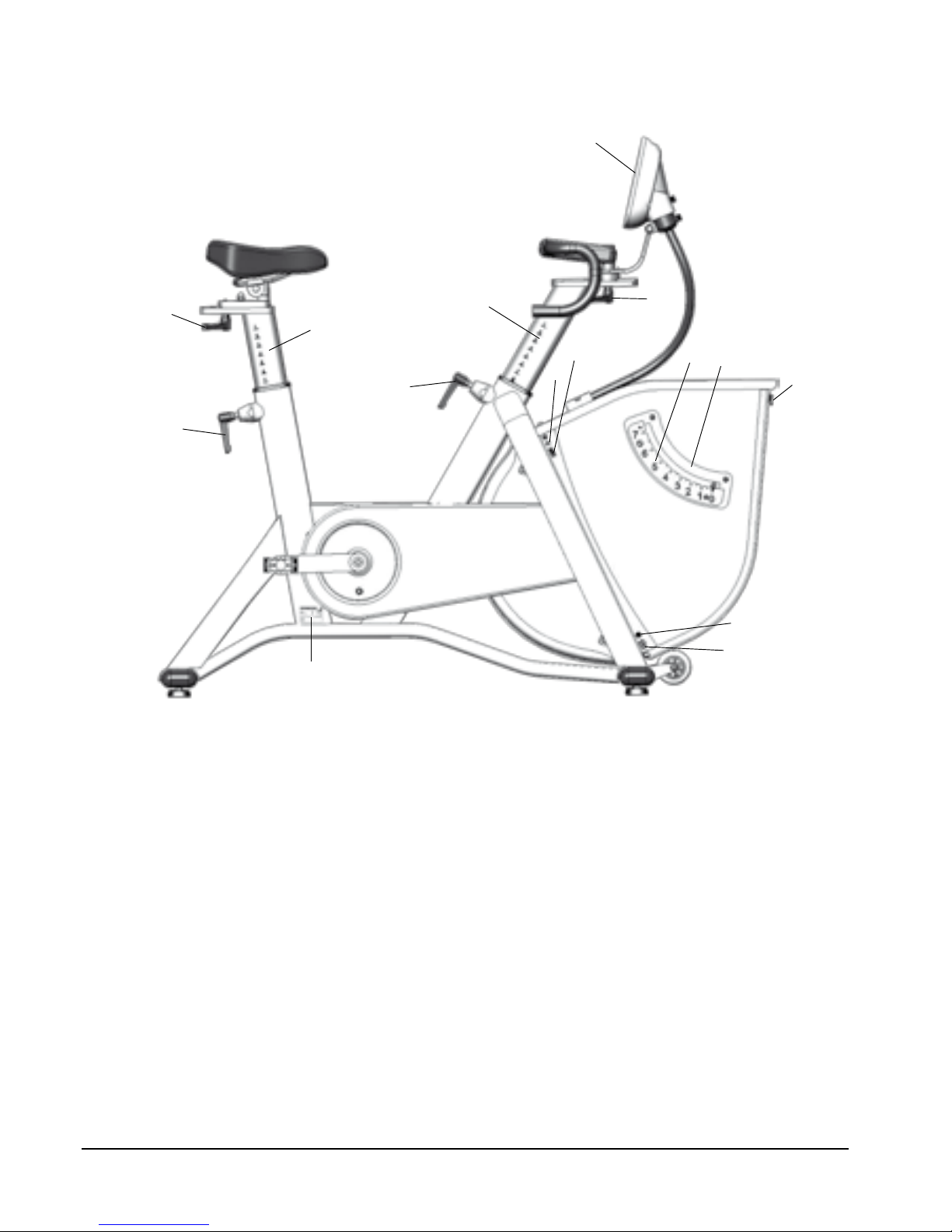
Fig: Overview
1) Knob for horizontal adjustment of saddle
2) Scale for height adjustment saddle
3) Locking handle for height adjustment saddle
4) Machine plate (serial number)
5) Knob for height adjustment of handlebar and display
6) Handlebar stem
7) Display
8) Knob for horizontal adjustment of handlebar and display
9) LED
10) Power switch
11) Screw for adjustment kp-scale
12) kp-scale
13) Locking for front cover
14) Power input
15) Locking for cable (power adaptor)
Fig: Overview
Page 8
LC4 / LC4r
8
Cycle adjustments
Adjustments of the bike
Crank Steel, 52T, 172.5 mm,
Q 146 mm
Pedals 9/16”, combi SPD / Clips
Saddle Moody
Seat post Vertically: 530-940 mm
(21"-37")
Horizontally: 60 mm
(2 1/3")
Handlebar Racing,
Ø31.8 mm at clamp
Handlebar stem Vertically: 500-910 mm
Horizontally: 60 mm (2 1/3")
Distance saddle - handlebar 140-840 mm
(6.7" - 32")
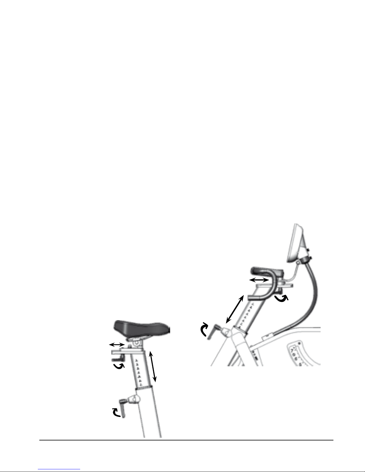
Cycle adjustments
Seat height should be adjusted to a comfortable
position. The appropriate height is to have the knee
slightly bent when the sole of the foot is centred over
the pedal axle with the pedal in the bottom position.
When adjusting the saddle height and vertical position,
loosen the respective locking handles. See Fig: Saddle
adjustment.
The handlebar setting should be in a comfortable
position when cycling. During longer exercise sessions
it is recommended to occasionally change handlebar
position. The handlebar can be adjusted both
horizontally and vertically. This is done by loosening
the respective locking handles. See Fig: Handlebar
adjustment.
NOTE! Be sure that the stem and seat post are inserted
to at least 100 mm in the frame. This is marked with
“MAX” on the stem.
Validation
Fig: Saddle adjustment
Fig: Handlebar adjustment
The following procedure ensures that the bike works
for daily use.
Check the HR function if you use chest belt, see •
section, on 'Heart rate'.
Check the braking force by putting on a certain •
workload and check that the load is applied.
Test by pedalling and check that a reasonable •
rpm is obtained - verify by a clock. Feel if the
pedals move smoothly. Listen for unusual sounds.
Remedy if necessary.
Adjust the handlebar and saddle and make sure •
they are securely attached and that the adjustment
is working properly.
Make sure the support legs are in position by •
rocking the bike. Tighten if necessary.
If something unusual is found during the daily
inspection that you cannot resolve, please call
customer service.
Page 9
1
Garmin
LC4 / LC4r
9
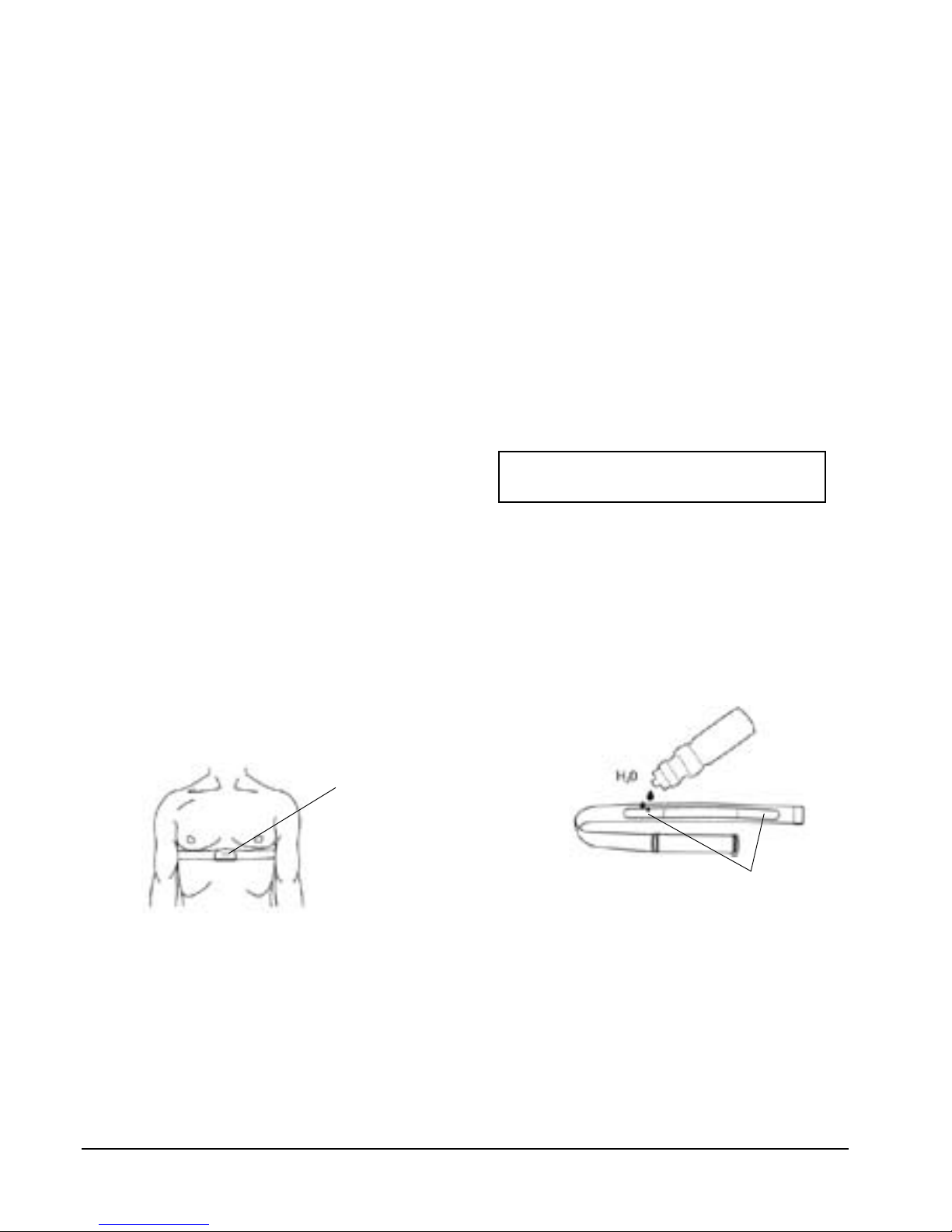
The user's heart rate can be measured with a chest
belt that senses the electronic output of the heart.
Chest belt ANT+ is supplied as standard.
Fuss-free HR measurement requires that the belt is
correctly placed. Make sure that your skin is clean
where the chest belt should be placed. When it is
correctly fitted the logo on the belt will be central and
readable, outward and upright, by another person.
The chest belt should be placed with a comfortable
tension around the mid section of the chest, just
below the breast muscle, see Fig: Placement chest belt.
Moisten the electrodes before use, see Fig: Moistening
the electrodes.
NOTE! Electromagnetic waves can interfere with the
telemetry system. Cellular phones are not allowed to
be used near the bike during test.
Pulse standard (chest belts)
The following pulse standard / chest belts can be
used:
Standard, uncoded 5K chest belts (5-5.6 kHz)•
Chest belts with ANT+•
Short range ANT+: 0.6-0.8 m (24"-31 ½")
Long range ANT+: 4-5 m (13-16 ft)
Range 5K: 0.8 m (31 ½")
Pairing display and chest belt
Normally the display connects to the first ANT+ chest
belt in "short range" and shows the heart rate until
the chest belt is outside the "long range". If there is no
ANT+ chest belt but a 5K chest belt in "short range",
the heart rate from the 5K chest belt is displayed until
the signal is lost.
ANT+ is prioritized and the first choice of the display.
5K is discriminated, but after 30 seconds with only
5K the display is locked to this chest belt as long as
you do not lose the signal.
Pulse function
Monark Exercise AB recommend that you
use an ANT+ chest belt for best function.
Fig: Placement chest belt
Fig: Moistening the electrodes (1)
Page 10
1
2
3
4
5
6
7
8
9
10
11
13
14
12
LC4 / LC4r
10
Sleep mode
Sleep mode is activated after 10 minutes if you do not
press any button or if no rpm is recorded.
All settings are saved, but the personal settings are
erased (to protect your personal privacy).
The meter wakes up when you press any button or
if rpm is recorded. The meter goes directly to 'Quick
start' (see separate section).
Display Description
The meter has the following functions:
Settings for different units of measurement •
It is possible to calibrate the meter to get the •
correct workload
Personal data such as age, max pulse, weight and •
gender can be set
USB port for continuous output of data to an •
external computer
Several different programs, see table ‘Available •
Programs’
The meter also shows current pulse as percentage •
of max. HR
The workload is rpm independent•
Display
Pedal revolution (RPM) pedal revolutions
/ min
HR bpm
TIME min:sec
Workload (WATT alt. kpm/min) Watt
Speed km/h
Distance km
Calories (KCAL) kcal
% Max HR %
LC4 LC4r
Astrand Training
YMCA METS
PWC -
Increment -
METS -
Training -
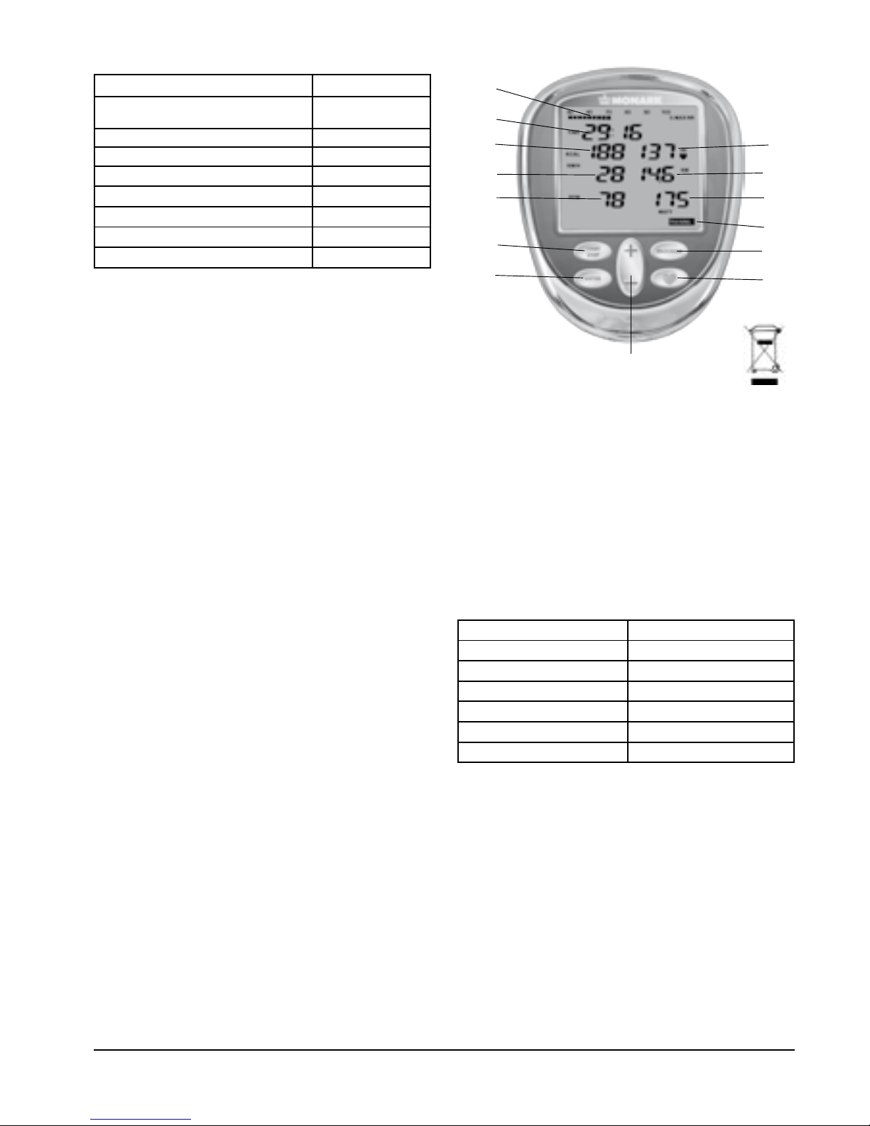
Fig: Display (Training)
1) % of max HR
2) Time
3) Kcal (estimated value)
4) Speed km/h
5) Pedal revolutions (rpm)
6) START STOP
7) ENTER
8) (+/-) button
9) Heart rate (HR)
10) Distance (km)
11) Workload (Watt)
12) Program
13) PROGRAM
14) HEART button
Available programs:
We recommend to use only the AC adaptor when
using the bike. Without the AC adaptor, there will be
no workload control and display alarm is activated.
Calibration and basic settings are saved even when
the power fails.
(The display can be powered by batteries, 4x1.5V,
R14, but only when you make the basic settings.)
If the values for rpm and watt start flashing during
use, the set workload requires higher brake power
than 7 kp. To solve this, increase the rpm or decrease
the set workload.
Page 11
dAtA
Weight kg 75
dAtA
dAtA
Age 35
dAtA
Max HR 185
Woman
Man
Unit
KM/H KM
ML/
MIN/ KG
KG
Unit
KM/H KM
ML/
MIN/ KPM/MIN
K G
Unit
KM/H KM
ML/
MIN/ KP
KG
Unit
KM/H KM
ML/
MIN/ WATT
KG
LC4 / LC4r
11
Alternative power / force display
The meter displays power in watts (default). If you
want to display the power in kpm / min instead, press
the HEART button for 5 seconds. Then you can
switch between WATT, KPM / MIN and current kpvalue using the (+/-) button. Press ENTER or wait 10
seconds to confirm and exit the setting.
NOTE!
Even if you select kp as unit, it is the power in watts
which is set in the background when you press (+/-)
button.
The displayed kpm / min is a simplified calculation
(1 kp = 10 N) according to Astrand's tables.
(Although the displayed kp value is correct and not rounded as
above. For all calculations in the display the exact value is used,
1 kp = 9.80665 N)
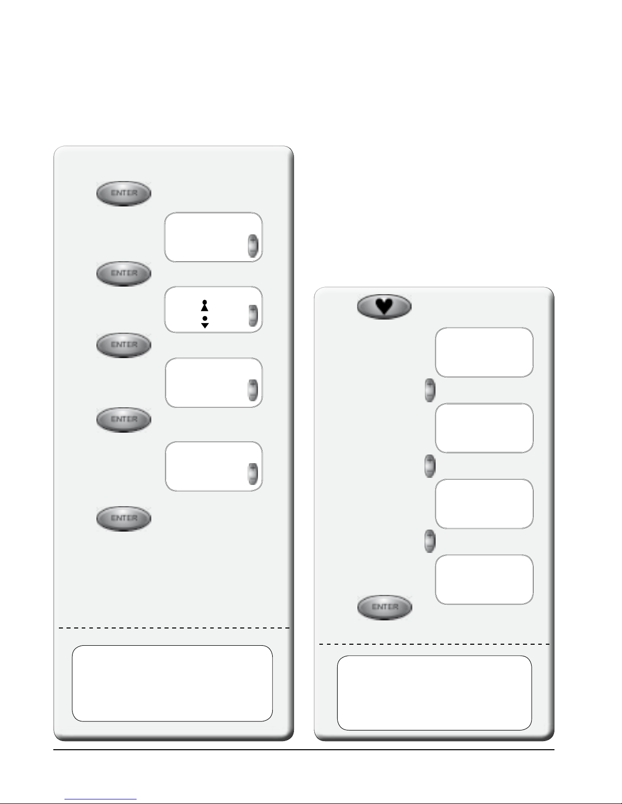
Set units
Default (kg, km, km/h, ml/
min/kg)
Press HEART button
for 5 seconds.
The display returns
to start view
You can switch
between these
different units
When the units you
want to use appears
in the display, press
ENTER to conrm
NOTE!
When you press the HEART button the
meter starts searching for a HR signal.
(Remember this if you also set the Steady
State.)
Press ENTER to
enter the menu for
Personal settings.
Usually you are asked to set the personal data needed
when you start a program or a test. This data can
also be set before, during e.g. "Warm up" in Training
program with this function.
Personal settings
Set
weight
Set
gender
Set
age
The display returns to
start view
Set
max HR
The meter suggests
an estimated max HR
based on your age
(220-age)
Change if desired.
The settings are saved until the meter goes
into sleep mode. When the display wakes
up the personal settings are changed to
default values (this is to protect your
personal privacy).
Page 12
Unit
KM/H KM
ML/
MIN/ KG
KG
ConStAnt
1.00
CAdEnCE
60
Id00
bASE
25
WATT
St-StAtE
3
HR
+2 +4 +6 +10-2-4-6-10 RF
(rpm)
+
LC4 / LC4r
12
Units
Kg, km, km / h, ml / min / kg are default. You can
switch between the different unit combinations with
(+/-) button.
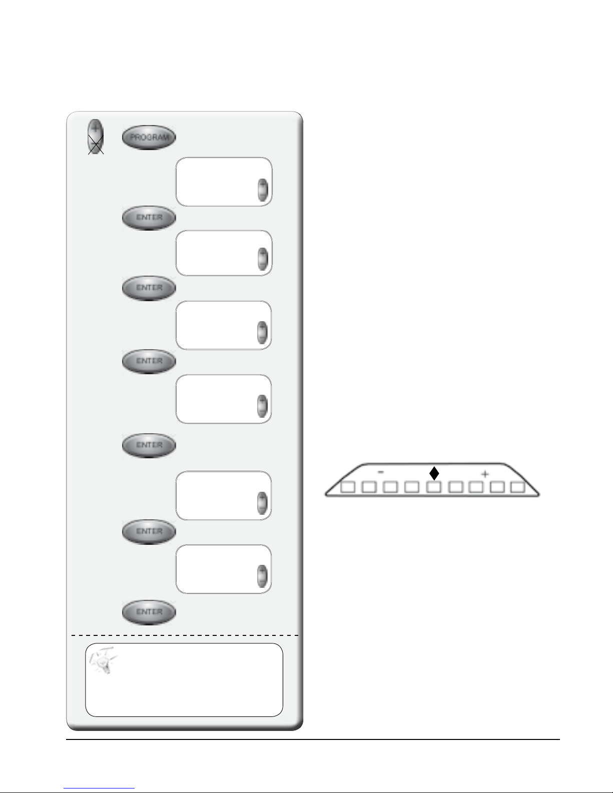
User settings
BikeID
This ID is a parameter that the PC software can
ask for. It is used to identify or number bikes when
multiple bikes are controlled by same PC or similar.
Set units
Set cycle
constant
Set metronome
cadence
Set cycle-ID
Set base
power
LC4
Set steady
State HR
LC4
LC4:
The display returns
to start view
green
(reference)
orange
red
yellow
orange
red
yellow
orange
orange
Fig: Metronome
Here you can make individual adjustments to
optimize the bike for your needs on first use and when
needed.
Cycle constant
The cycle constant is as default set to 1.00. Change
using the (+/-) button.
When the cycle constant is set to 1.00 the power is
measured at the flywheel. This is used in Astrand test,
YMCA etc.
When the cycle constant is set to 1.05 the power
is measured at the crank. This is often used on
electronically-braked bikes.
Metronome cadence
Metronome diodes show pedalling revolutions (rpm)
relative to the set reference value. The metronome is
located at the back of the meter. The default value is 60
and can be adjusted with (+/-) button. The green LED
in the middle flashes twice for each pedal revolution
which helps to keep the right pedal cadence, see Fig:
Display and Fig: Metronome.
The meter can be rotated so that the rider does not
see the values in the display, but only sees the flashing
diodes (in order to keep the right pedal cadence).
If START STOP is pressed, or if no
button is pressed for 20 seconds (in
all steps), the changes are saved and
the display returns to normal with
the new settings active.
LC4r:
The display returns
to start view.
Press PLUS and PROGRAM
for 5 seconds to
set 'User settings'.
Page 13

1
2
3
4
5
6
LC4 / LC4r
13
Fig: Display
1) START STOP
2) ENTER
3) (+/-) button
4) HEART button (pairing meter and chest belt)
5) PROGRAM
6) Metronome (on the back)
Base Power
(Except RC4r)
Default value which is used as "idle" power when no
program or test is active. The default value is 25 but
can be adjusted with (+/-) button.
Steady State HR
(Except RC4r)
Default value is (±)3 but can be adjusted between
1 and 10 with (+/-) button.
Steady State (SS) HR is used only in Astrand program.
SS is checked by comparing the mean value of HR
during the period 4:45 to 5:00, and the mean time
between 5:45 to 6:00. If the difference between these
two values is the same or less HR is counted in SS.
Page 14

KP
LC4 03 10
0
C 100
112 2.0
KP
KP
KP
LC4 03 10
0
C 100
58 0.0
KP
KP
LC4 03 10
0
C 100
179 4.0
KP
LC4 03 10
0
C 100
319 6.0
KP
+
LC4 / LC4r
14
Calibration
Two short beeps are heard and the
calibration is nished.
The bike is ready to use.
Check the potentiometer
value at 0 kp
Zero the scale, see ‘Scale - Zero adjustment’ •
Release the brake belt tension by lifting the •
pendulum over 0.5 kp (the motor starts).
(The brake belt tension can also be loosened •
by running the engine manually. This is done by
pressing (-) in the calibration mode.)
Move the pendulum
to current value and
hold it still until the
potentiometer value
stabilized
Press ENTER for next
step
Repeat according to
the pictures to the
right
Calibration electronics
Usually it is not necessary to recalibrate the cycle
electronically, but it should be done after each service,
change of electronic part, movement or if you adjusted
the 0-index.
The calibration coefficient calculated by the computer
is stored in main memory. No matter when the power
is turned on, the last stored calibration will be placed
in main memory. New calibration automatically
replaces the old.
NOTE!
The pendulum must be kept still at the
different positions. This is done by pressing
down the pointer into the groove on the scale
at each kp value.
= Tightens brake belt
= Slackens brake belt
Manual motor control
By pressing the (+/-) button in the calibration mode,
the motor can be run manually if rpm is less than
30. This is to ensure the functioning of the engine
for service or support, and to release the brake belt
tension.
Press START STOP
and PROGRAM for
2 seconds to enter
calibration mode.
To calibrate the bike, you must have a 4 kg calibration
weight. This is available as an accessory.
If you have started the calibration mode
but change your mind, you can press the
START STOP button to exit without saving.
(However, if you press ENTER the calibration
process has begun and must also be completed.)
NOTE!
Calibration can only be done from the display!
Page 15

LC4 / LC4r
15
Fig: Control loose brake belt
Fig: Zero position
Fig: 2 kp.
Fig: 4 kp.
Fig: 6 kp.
Fig: 0 kp.
Page 16

1
2
3
4 kg
1
3
4
2
1
2
3
LC4 / LC4r
16
Zero adjustment of scale
Check that 0-index (3) on the scale (2) is in line with
the pendulum pointer when the bike is at a stand
still and the brake belt is loose. If not, an adjustment
must be done. Loosen the screw and adjust the scale.
Tighten the screw (1) after adjustment. See Fig:
Adjustment scale.
Fig: Calibration
1) Kp-scale
2) Pointer
3) Spring
4) Calibration weight 4 kg (accessory)
Fig: Adjusting scale
1) Screw
2) Kp-scale
3) 0-index
Calibration
All LC4 are calibrated in the factory, but a calibration
of the pendulum can still be done to verify this. If so,
please do the following.
Open the front cover. Check that the brake belt (3) is
loose. If not, move the pendulum to 0.5 kp and hold
it there a while to loosen it. Unhook the brake belt
from the spring. Check that scale 0-index is in line
with the pointer. Adjust if necessary, see section ‘Zero
adjustment of scale’.
Calibration weight 4 kg (Art. No: 9000-211) is
hooked on the spring.
NOTE!
The flywheel must be completely stopped before the
weight is hung on!
This weight (4 kg) can, when properly adjusted, be
read at the corresponding point on the scale. If there is
a deviation, adjust the pointer to the correct position
by adjusting the weight (2) inside the pendulum. To
change the adjustment weight loosen the adjustment
screw (1). If the pointer shows too low, the internal
weight must be moved upwards. If the pointer shows
too high, the adjustment weight is moved down.
This process is repeated until pointer is in the correct
position. Hook the brake belt in the spring and close
the front cover.
Check the calibration of the pendulum weight once a
year or when needed.
Fig: Pendulum
1) Adjustment screw
2) Adjustment weight
3) Brake belt
Page 17

1
2
3
4
5
6
7
9
8
KP
LC4 03 10
0
C 100
58 0.0
KP
LC4 / LC4r
17
Current
potentiometer
value
Fig: Display ’Calibration mode’
1) Bike model
2) Current potentiometer value
3) START STOP
4) ENTER
5) Software version
6) Hours in use
7) Cycle constant (1.00)
8) Calibration point
9) PROGRAM
Next calibration point
Current potentiometer value
For best flexibility we recommend a potentiometer
value between 40 and 60 at 0 kp.
Error message: CalErr - if the value is outside the
window.
NOTE!
Potentiometer values shown in the photos are
examples only, varies depending on the potentiometer
value at 0 kp.
Page 18

TIME
KCAL HR
KM/H KM
RPM WATT
TIME tot
KCAL HR
KM/H KM
RPM WATT
TIME HI
KCAL HR
KM/H KM
RPM WATT
TIME Lo
KCAL HR
KM/H KM
RPM WATT
LC4 / LC4r
18
Personal data can be set for estimated HR (default
HR is 185). See ‘Personal settings’.
Average
value
Max valueMin value
Press ENTER (for 5 seconds
during the test) and a new test is
started with the same settings.
Press START STOP (for 5 seconds
during the test) and the test is
reset.
Interval training
Start with eg. 300 W - press START
STOP and the cycle goes down to the
base power - press ENTER and the
power returns to the previous power
(300 W).
TRAINING
Press START STOP in 'Quick Start' and the display
begins to show, count and log values. Press START
STOP again and the test is completed and the results
are displayed on three pages in the display and you can
switch between the pages by pressing (+/-) button.
Workload adjustment
The power is adjusted with (+/-) button, press and
hold for quick adjustment. The power can be set
between 15 and 700 W in 5 W steps.
QUICK START
’Quick start’ can be used as a separate program. (If
START STOP is pressed, the TRAINING program is
activated.)
The program is active and starts with base power,
adjust with (+/-) button. No time is counted so the
test person can warm up, use it as a 'quick start' or
train without logging any values.
Start Training
program
Stop Training
program
To end the Training program,
press START STOP and the
results are displayed on
three pages.
Training
Page 19

dAtA
Weight kg 75
dAtA
Age 35
dAtA
Max HR 185
TIME
HR
METS L/MIN
RPM WATT
TIME tot
METS HR
L/MIN
RPM WATT
TIME HI
METS HR
L/MIN
RPM WATT
TIME Lo
METS HR
L/MIN
RPM WATT
LC4 / LC4r
19
During the test METS and l/min are continuously
counted and displayed.
Calculation
METS values are displayed and calculated from the
current workload. The two VO
2
values displayed
during the test continuously calculate the average
value for 5 seconds.
The formula used (values from ASTRAND original
table) to calculate VO
2
at different workloads is:
0.2333 ... l / kpm = 0.01428 L / W (2.8 l / min at 1200
kpm)
This is according to Astrand's table between 150 W
and 300 W, and a good approximation for 15-700 W
and a cadence of about 50-65 rpm.
Stop METS
program
To end the test, press START
STOP and the results are
displayed on three pages.
Set weight
Set age
Set max HR
Start METS
program
Max valueMin value
References / Literature:
Astrand P-O, ”Ergometri - konditionsprov”, Monark, Sverige•
Åstrand I, ”Aerobic work capacity in men and women with special •
reference to age”, Acta Physiol Scand. 49 (suppl. 169), 1960
Astrand P-O, ”Experimental studies of physical working capacity in •
relation to sex and age”, Munksgaard, Köpenhamn, 1952.
Astrand P-O, Rodahl K, ”Textbook of Work Physiology”, McGraw-•
Hill, New York, 1970.
The meter suggests an
estimated max HR based
on your age (220-age)
Change if desired.
Press ENTER (for 5 seconds
during the test) and a new test is
started with the same settings.
Press START STOP (for 5 seconds
during the test) and the test is
reset.
Average
value
METS
Page 20

dAtA
Weight kg 75
dAtA
Age 35
dAtA
Max HR 185
TIME
HR
RPM WATT
dAtA
Woman
Man
TIME tot
KCAL HR
KM/H KM
RPM WATT
TIME HI
KCAL HR
KM/H KM
RPM WATT
TIME Lo
KCAL HR
KM/H KM
RPM WATT
(
)
LC4 / LC4r
20
Astrand
(Except LC4r)
Max valueMin value
Press ENTER (for 5 seconds
during the test) and a new test is
started with the same settings.
Press START STOP (for 5 seconds
during the test) and the test is
reset.
It is recommended not to adjust the braking
power after the first three minutes.
Average
value
Set weight
Set gender
Set age
Set max HR
Start Astrand
program
The meter suggests an
estimated max HR based
on your age (220-age)
Change if desired.
Stop
Astrand
program
If Steady State is reached the test
stops after 6 minutes. If not, the
test continues until Steady State
is reached or the time reaches
12 minutes.
After 6 minutes, the test can also
be stopped manually.
Page 21

LC4 / LC4r
21
Astrand
(Except LC4r)
The test is automatically stopped after six minutes if
Steady State (SS) is active. If not, the test continues
until SS is reached or the time reaches 12 minutes.
Steady State (SS) is checked by comparing the average
HR during the period 4:45 to 5:00 with the average
HR during the period 5:45 to 6:00. If the difference
between these two average values is the same or less
considered SS.
When the test is completed the results are calculated
and shown directly in the display.
You can stop the test manually after six minutes by
pressing START STOP even if SS is not active (an
error message is shown). The result is calculated and
displayed.
References / Literature:
Astrand P-O, ”Ergometri - konditionsprov”, Monark, Sverige•
Åstrand I, ”Aerobic work capacity in men and women with special •
reference to age”, Acta Physiol Scand. 49 (suppl. 169), 1960
Astrand P-O, ”Experimental studies of physical working capacity in •
relation to sex and age”, Munksgaard, Köpenhamn, 1952.
Astrand P-O, Rodahl K, ”Textbook of Work Physiology”, McGraw-•
Hill, New York, 1970.
Explanations to error messages:
LO Hr
HI Hr
Err
No SS
The end pulse is too low and outside
the Astrand tables so no results can be
calculated
The end pulse is too high and outside
the Astrand tables so no results can be
calculated
Another reason why no results can be
obtained
The test is cancelled manually without
SS after 6 minutes or no SS at time 12
minutes
Page 22

dAtA
Weight kg 75
dAtA
Woman
Man
dAtA
Age 35
dAtA
Max HR 185
TIME
HR
RPM WATT
LC4 / LC4r
22
YMCA
(Except LC4r)
The test is automatic after it has been started. Two
or three levels (6 or 9 minutes) run automatically
according to the table on the next page.
After six or nine minutes the test stops automatically
and the YMCA will stop flashing. The results are
shown in the display.
You can stop the test manually after two levels (6
minutes) by pressing START STOP and the results are
calculated if the values are within the tables.
If the test values are outside tables so that no results
can be given, you will hear a long beep and an error
message appears.
Explanations to error messages:
LO Hr
HI Hr
Err
The end pulse is too low and outside
the Astrand tables so no results can be
calculated
The end pulse is too high and outside
the Astrand tables so no results can be
calculated
If the test is stopped manually too early,
or other reasons that no results can be
given
References / Literature:
Golding L. A, Myers C. R, Sinning W. E, Y´s way to physical fitness“, •
YMCA of the USA, Rosemont, IL, 1982
Set weight
Set gender
Set age
Set max HR
Start YMCA
program
Stop YMCA
program
The test stops automatically
after 6 or 9 minutes
(depends on start HR)
Press ENTER (for 5 seconds
during the test) and a new test is
started with the same settings.
Press START STOP (for 5 seconds
during the test) and the test is
reset.
The meter suggests an
estimated max HR based
on your age (220-age)
Change if desired.
Page 23

150 kpm/min / 25W
450 kpm/min / 75W
300 kpm/min / 50W
750 kpm/min / 125W
600 kpm/min / 100W
600 kpm/min / 100W 450 kpm/min / 75W
< 103
> 102
> 122 > 137 < 138 < 123
300 kpm/min / 50W
900 kpm/min / 150W 750 kpm/min / 125W 600 kpm/min / 100W
1350
225
1200
200
1050
175
1200
200
1050
175
900
150
1050
175
900
150
1350 kpm/min
225 W
< 120 120 - 135 > 135
< 90
90 - 105 > 105
>135 <120 120 - 135 >135 <120 120 - 135
LC4 / LC4r
23
YMCA
(Except LC4r)
Men:
Women:
Level 1:
HR:
Level 2:
HR:
Level 3:
Level 1:
HR:
Level 2:
HR:
Level 3:
NOTE! The given HR values are at the end of each level
Page 24

dAtA
Age 35
dAtA
Max HR 185
TIME NEXT
HR
RPM WATT
dAtA
TIME 3:00
dAtA
Init WATT 25
dAtA
Step WATT 25
TIME End
Heart rate
RPM WATT
TIME HI
Heart rate
RPM WATT
TIME Lo
Heart rate
RPM WATT
LC4 / LC4r
24
Increment
(Except LC4r)
Remaining
time to
next step
Current
time
Set time for
each step
Set age
Set max HR
Start
Increment
program
Stop
Increment
program
The test is stopped when:
The cadence is <30 for more •
than 5 seconds
When you press START STOP •
700 W workload is achieved•
Set start
power
Set power
increase per step
The results are displayed on three
pages that you switch between
with the (+/-) button:
Press ENTER (for 5 seconds
during the test) and a new test is
started with the same settings.
Press START STOP (for 5 seconds
during the test) and the test is
reset.
End value Max valueMin value
NOTE!
If the meter does not get any rpm indication at
start, the test stops. To restart, press ENTER.
The meter suggests an
estimated max HR based
on your age (220-age)
Change if desired.
Page 25

LC4 / LC4r
25
Increment
(Except LC4r)
Time for each step
Set the time (minutes:seconds) for each single step.
Preset time setting the first time is 3 minutes.
Start power
Set the first power level.
Power increase per step (step)
Set the power increase between each step of 5 to 200
W. Last value is presented as default.
Test procedure
The display begins with the start power (which is
specified in ‘Start Power’) and begins the countdown
to the next step. The display will increase the power
at the specified power increase each time the set time
has passed and a new countdown begins. At the same
time you hear a beep.
The test is automatic after it has been started.
If the test is stopped because of the low rpm it starts
automatically even if the rpm increases again.
About Increment test
Increment is a testing protocol, where the power is
increased according to a predetermined schedule. An
increment is used to see the HR increase in relation
to the rising power. It is used in both submaximal to
maximal tests to track the maximum capacity.
The test continues until the test manager or test person
cancels the test.
Page 26

dAtA
Weight kg 75
dAtA
Age 35
P 150
TIME NEXT
HR
RPM WATT
Cool 5 m
Cool 3 m
Cool 1 m
0:00
...
>
Second last
End value
Results
02:00
Watt
25
Init
Watt
25
LC4 / LC4r
26
Stop PWC
program
PWC
(Except LC4r)
Set test level
Set weight
Set age
Set start
power
Set power
increment per step
The program is automatic until the test HR level is exceeded.
The test can always be stopped
manually by pressing START
STOP. Then the display shows
the analysis pages but "Err"
is displayed instead of watts
value and watts / kg results,
if the test is stopped before
the countdown started and
only the complete step data is
displayed.
To see the results that appear on each page, see the table on
the next page.
Press ENTER (for 5 seconds
during the test) and a new test is
started with the same settings.
Press START STOP (for 5 seconds
during the test) and the test is
reset.
The test continues
until the selected
HR level is reached
The test is stopped when:
HR level is reached (cool down •
starts)
You press START STOP (if you •
press START STOP after the HR
level reached the results are
displayed)
Remaining
time to
next step
Current
time
The meter suggests a level based on
your age and estimated max HR.
Power increase (two set)
25 W step 2 min / 50 W step 3 min
Page 27

LC4 / LC4r
27
PWC
(Except LC4r)
PWC test level
The meter suggests a level based on your age. Can be
adjusted with (+/-) button.
PWC target HR watt calculation:
The estimated watt value at target HR (WPT) is
calculated from the following data:
W1 = Watts value set in penultimate step
W2 = Watts value set in the last step
P1 = 15-second average HR at the end of the
penultimate step
P2 = 15-second average HR at the end of the last
step
PT = Target HR: 130, 150 or 170 beats / min
Formula for the WPT:
WPT = W1 + (W2-W1)x(PT-P1)/(P2-P1) [W]
Relative WPT:
WPT / kg = WPT / Weight [W / kg]
For further information please refer to the reference
literature.
Age (year) Program
<30 P170
30-50 P150
>50 P130
References / Literature:
Dr. Theodor Stemper, Diplom-Sportlehrer•
ROST, R, H. HECK, W. HOLLMANN, Die Fahrradergeometrie in •
der Praxis. Broschüre der BAYER AG
STEMPER, Th.: Gesundheit - Fitness - Freizeitsport. Bund-Verlag, •
Köln 1988 (zu beziehen über SSV-Verlag, Hamburg)
Power step
The display shows time 2:00 and power 25 W. Switch
with (+/-) button to time 3:00 and power 50 W. Press
ENTER to save.
Start power
The display shows "Init". Set the initial power of the
first step between 25 and 400 W with 25 W steps.
Default value is 25 W. Press ENTER to save.
How it works
At the end of each step calculated average HR during
the last 15 seconds, a beep sounds, 25 W or 50 W
is applied workload, and a new countdown starts.
In the first five seconds of the next steps the display
shows test time, workload and estimated average HR
during the previous step. During these five seconds
the values flash.
This continues until the 15-second average HR is
higher than the target HR (130 / 150 / 170). Then the
test is stopped, a beep sounds, the workload reverts
to start power, the final 15 seconds of average HR is
displayed. The text "COOL" is displayed and the sixminute countdown starts. A 15-second average HR is
displayed after 1, 3 and 5 minutes of the countdown.
You can skip the "cool down" by pressing the START
STOP and the results appear instantly.
Page Results that are displayed
Results Total test time (end time), chosen test,
total kcal, target HR, calculated result
W
PT
/kg and calculated result W
PT
End value Total test time (end time), chosen test,
target HR (end value) and calculated
value per step
Second last Second last test time, chosen test, step
HR and calculated value per step
...> Chosen test, step HR and calculated
value per step
0:00 Test time, chosen test, start HR and
calculated value per step
Cool 1 m Time C1:00, chosen test and step HR
Cool 3 m Time C3:00, chosen test and step HR
Cool 5 m Time C5:00, chosen test and step HR
Results
After ‘cool down’ two quick beeps are heard and the
meter calculates and displays the results. The results
are displayed on several pages that you switch between
with the (+/-) button:
NOTE!
The displayed value for calories is the total estimated
calorie consumption incl. ’cool down’.
Page 28

1
Garmin
LC4 / LC4r
28
Testing using LC4
The versatility of the LC4 enables it to be utilized in
a variety of testing environments. The precision and
reproducibility of the test values obtained with the
bike, along with the uncomplicated way to set up
the tests, means the bike can be used in clinical work
tests, in occupational health services for the fitness
tests as well as fitness centers, schools, sports clubs
and the like.
In general, one should note that stresses on the tested
person can become quite severe, whether in a clinical
work test or a simple fitness test in physical activity
contexts. As a precaution, it may be advisable, prior
to beginning an exercise protocol, that each subject
consults with a physician.
Before testing, the operator should review the entire
protocol operation with the test person, explaining
the work which will be required and the duration of
the procedure. One should also agree on how the test
person shall give signs of any fatigue, chest pain or
other abnormal physical reactions.
The test person should not engage in heavy physical
activity for several hours prior to testing to establish
maximum oxygen consumption. In addition, all
testing and exercise protocols should be performed
a reasonable time after meals. The test person should
also refrain from smoking within an hour of the
testing period.
The tested person shall also have the appropriate
clothing for a work test. Training suit or loosefitting clothing is best. More detailed instructions
are rarely needed, regarding the ride, but it may
still be appropriate for the test leader to give some
advice on pedalling, saddle height and position of
the handlebars. It should be comfortable to ride. The
appropriate height of the saddle is when the knee is
slightly bent when the sole of the foot is centred over
the pedal axle with the pedal in the bottom position.
Let the test subject try to ride with low workload and
see how it feels to hold a steady rpm.
Finally, the chest belt shall be put on, see Fig: Placement
chest belt for correct position. Check for a minute
that a proper heart rate is displayed. The baseline
heart rate may also be of assistance in determining the
nervousness of the test subject. It may be appropriate
to let the test person rest long enough before the test so
a more or less stable resting heart rate can be read.
Test person enforcement
The bike performs automated tests virtually by itself,
requiring minimal intervention by the test operator.
This allows the operator to pay careful attention to
the test person without distraction. The response to
the exercise protocol can be accurately estimated and
appropriate action taken to assist the test person, if
necessary. Some programmes have sections where
the test person may develop significant physical
activity. The effect on the test person should not be
underestimated.
During the test it is important to observe the test
person's appearance and heart rate. The testing should
be stopped immediately if the test person reports chest
pain, difficulty in breathing, etc. A system of prompt
medical attention should be set up prior to testing, in
case of emergency.
The test person may also have difficulty in keeping a
steady pedalling speed. This is of minor importance
(except in cases where the program assumes a constant
braking force, since the effect is automatically adjusted
to the correct value as long as the pedal speed is at
least 30 rpm. However, it is important to consider
what each test documentation says about the pedal
speed.
Fig: Placement chest belt
Fig: Moistening the electrodes (1)
Page 29

LC4 / LC4r
29
Reviewing results
The maximum oxygen uptake is a standard measure
of the condition of the heart- and lung-functions.
Dependent on the linear relationship between work
and oxygen uptake and between work and heart rate,
the heart rate response to work may be used to estimate
the oxygen consumption. If the maximum heart rate
is considered, the maximum oxygen consumption
may be determined.
The YMCA and Astrand protocols estimate
the maximum oxygen consumption, based on a
submaximal workload while all others report the
oxygen consumption required by the final workload.
The estimated maximum oxygen consumption
derived from some of the ergometer tests is subject
to the error of the “age related predicted maximum
heart rate“. Although there is a definite and linear
relationship between work and oxygen uptake, there
are some differences in actual oxygen uptake based
on individual work efficiency. Test persons who are
less familiar with bike exercise and those individuals
who are less fit, are more likely be less efficient than
those who ride bikes frequently.
It should be noted that these results are estimates or
predictions of maximal response and have a greater
chance of being in error than if the individual were
tested to their actual maximum value. Interpretation
should therefore be made more carefully with an
understanding of the possibility of errors in the
methodology.
Power calculation
1 rpm = that a point on the flywheel moves 6 meters
per minute.
50 rpm = 300 m
2 kp force makes 2 x 300 = 600 kpm/min
100 rpm= 600 m
1 kp force makes 1 x 600 = 600 kpm/min
Exact calculation:
Watts = rpm x kp x 0.98065
"Rule of thumb" calculation:
Watts = rpm x kp
(2% error, but may be good enough in many
cases)
Page 30

LC4 / LC4r
30
Symptoms Probable Cause / Corrective Action
The display is not working Check that there is power in the socket and that no fuse has blown. •
If there is power in the socket but the display still does not work, contact the •
service centre.
LED does not light up No current in the outlet. Check the fuses. •
Power switch disconnected on the bike. •
Check cables and connections. •
Correct power adaptor? Check that the transformer information (voltage, •
current, polarity, AC / DC) in section ‘Facts’ complies with the transformer
which is used.
No connection to PC Check cables (connections and type). •
No workload Pendulum stuck. Contact service centre for action / replacement. •
Check calibration.•
Check that brake belt is hooked in the spring.•
No heart rate Check that the battery is alright in the chest belt, moisten your thumbs and •
click on the electrodes, a low clicking sound will be heard at the battery cover,
alternatively that the heart rate is displayed in the computer software.
Make sure the belt fits correctly on the test person, see Fig: Placement of chest •
belt in section ‘Heart Rate’, and that the strap is sufficiently tightened. Moisten
the electrodes, in severe cases it may be necessary to use gel alternative, one
drop of dish washing liquid mixed in water. Pulse signal strength varies from
person to person. Try the belt with a person known to have a good pulse
wearing a chest belt.
Check for loose cables or jack if you have a plug-in receiver. Use another HR •
receiver (HR watch or test bike monitor) to check the chest belt.
Check that it is the correct receiver and that it is in the correct place. If it have •
a round Polar logo, the logo should be readable.
Uneven heart rate Use an external unit, for example a HR watch, to check if it also indicates an •
irregular pulse. If this is the case, there is probably a disturbance in the room.
The disturbance may be electronic fields from power cables, elevators, lamps
etc. or other electronic devices which are too close (eg. cell phones). Move the
bike to a different location in the room or change rooms. If an irregular HR
remains it should be checked manually. If the HR remains irregular at work
the person's health should be examined.
No rpm reading Check cable.•
Unable to calibrate force The potentiometer shaft is not attached to the pendulum shaft, tighten the •
screw.
The potentiometer is misadjusted. Check the menu for calibration and that •
potentiometer value is within the recommended window. If not, contact
service.
Troubleshooting guide
Page 31

LC4 / LC4r
31
Symptoms Probable Cause / Corrective Action
There is a click noise when pedalling
(increases with the weight)
The pedals are not tight. Tighten them or change pedals. •
The crank is loose. Check, tighten. •
The base bearing is loose. Contact your dealer for service.•
CalErr shows in the display Incorrect calibration or not calibrated at all. Calibrate the Ergometer.•
Scratching sound is heard when
pedalling
Check that the carriage block is taken off and that nothing is against the •
crank, chain, or wheel except the brake belt.
There’s a click noise and a squeak noise
when pedalling
Loosen the chain.•
Any problems with the computer
software
Send an email to the software developer HUR labs support: •
support@hurlabs.com
Page 32

Warranty
EU countries - Private use
If you are a consumer living in the EU you will have
a minimum level of protection against defects in
accordance with EC Directive 1999/44/EC. In short,
the directive states that your Monark dealer will be
liable for any defects, which existed at the time of
delivery. In case of defects, you will be entitled to have
the defect remedied within a reasonable time, free of
charge, by repair or replacement.
EU countries - Professional use
Monark Exercise products and parts are guaranteed
against defects in materials and workmanship for a
period of one year from the initial date of purchase
of the unit. In the event of a defect in material or
workmanship during that period, Monark Exercise
will repair or replace the product. Monark Exercise will
not, however, refund costs for labour or shipping.
Other countries
Monark Exercise products and parts are guaranteed
against defects in materials and workmanship for a
period of one year from the initial date of purchase
of the unit. In the event of a defect in material or
workmanship during that period above, Monark
Exercise will repair or replace (at its option) the
product. Monark Exercise will not, however, refund
costs for labour or shipping.
Service check and Maintenance
It is important to carry out a regular service on your
ergometer, to ensure it is kept in good condition.
Always keep the bike clean and well lubricated.
Service action:
We recommend isopropyl alcohol to disinfect the •
surface of the bike. Use a damp but not wet cloth to
clean the surface you wish to disinfect.
Surface treatment with a rust inhibitor, especially •
when the bike is clean and the surfaces are dry This
is done to protect the chrome and zinc parts as well
as the painted parts (4 times per year).
Check now and then that both pedals are firmly •
tightened. If not the threading in the pedal arms
will be damaged. When the Ergometer is new it
is important to tighten the pedals after 5 hours of
pedalling (4 times per year).
Check that the pedal crank is secure to the crank •
axle (4 times per year).
Be sure that the pedals are moving smoothly, and •
that the pedal axle is clear of dirt and fibres (4 times
per year).
When cleaning and lubricating be sure to check that •
all screws and nuts are properly tightened (twice a
year).
Check that the chain is snug and there is no play in •
the pedal crank (twice a year).
Check that pedals, chain and freewheel sprocket are •
lubricated (twice a year).
Be sure that the brake belt does not show significant •
signs of wear (twice a year).
Check that the handlebars and seat adjustment •
screws are lubricated (2 times per year).
Be sure that all moving parts, crank and flywheel •
are working normally and that no abnormal play
or sound exists. Play in bearings causes fast wearing
and with that follows a highly reduced lifetime.
Check that the flywheel is placed in the center and •
with plane rotation.
Grind the brake belt contact surface, see section •
‘Brake belt contact surface’ (once a year).
Service
Note!
Make sure the voltage indicated on the appliance corresponds to the local mains voltage before making
connections.
Note that the text about service and maintenance is
universal and that all parts may not be relevant to
your bike.
LC4 / LC4r
32
Page 33

If the meter is battery-operated, the batteries are in a
separate package at delivery. If the storing time has
been long the battery power can be too low to make
the computer act correctly. Batteries must then be
changed.
Flywheel bearing
The flywheel bearing is long-term greased and requires no supplementary lubrication. If a problem
arises, please contact your Monark dealer.
Crank bearing
The crank bearing is greased and normally requires
no supplementary lubrication. If a problem arises,
please contact your Monark dealer.
Transportation
During transport the brake cord should be tightened
to prevent it from falling off the flywheel.
Replacement of brake belt
To replace the brake belt remove covers if necessary.
Make sure that the belt is loose.
Pendulum bike with engine:
To loosen the brake belt on pendulum bikes with
engine, connect power to the unit and raise the
pendulum to 4 kp. Hold it there until brake belt is
loose. Please note how the belt is assembled. Remove
it from the bike. Attach the new brake belt and
assemble the bike in reverse order.
Weight basket bike:
To loosen the brake cord on cycles with a weight
basket set the basket to its upper position. Loosen the
lock washer that is holding the cord and remove it
from the tension center. Loosen or cut off the knot on
the other end of the cord and then remove the whole
cord from the bike. When assembling a new brake
cord, first enter one end into the hole in the tension
center, and tie a knot and let the knot fall into the
bigger part of the hole. Lock the end of the cord with
the lock washer.
Brake belt contact surface
Deposits of dirt on the brake belt and on the contact
surface may cause the unit to operate unevenly and will
also wear down the brake belt. The contact surface of
the flywheel should be smoothed with fine sandpaper
and any dust removed with a clean dry cloth.
Remove any potential covers and all workload on
the brake belt and then remove it. Grind with a fine
sand paper. Grinding is easier to perform if a second
individual cautiously and carefully pedals the cycle.
Irregularities on the brake belt contact surface are
removed by means of a fine sand paper or an abrasive
cloth. Otherwise unnecessary wear on the brake belt
may occur and the unit can become noisy.
Always keep the brake belt contact surface clean and
dry. No lubricant should be used. We recommend
replacing the brake belt when cleaning the contact
surface. In regard to assembly and adjustment of the
brake belt, see ‘Replacement of brake belt’.
Manual pendulum bike / exercise bike:
To loosen the brake belt on the bike remove all tension.
Please note how the belt is assembled. Remove it from
the bike. Attach the new brake belt and assemble the
bike in reverse order.
NOTE!
When replacing the brake belt it is recommended
to clean the brake surface. See ‘Brake belt contact
surface’.
Batteries
Fig: Brake belt contact surface
LC4 / LC4r
33
Page 34

Chain 1/2“ x 1/8“
Check the lubrication and tension of the chain at
regular intervals. In the middle of its free length the
chain should have a minimum play (1) of 10 mm (1/4
inch). See Fig: Chain adjustments. When the play in
the chain is about 20 mm (3/4 inch) the chain must
be tightened. Otherwise it will cause abnormal wear
of the chain and sprockets. Therefore it is always
recommended to keep the chain play as small as
possible. Loosen the hub nut (2) on both sides and
tense the chain with the chain adjuster (3) when
needed.
When the chain has become so long that it can no
longer be tightened with the chain adjusters it is worn
out and should be replaced with a new one.
To adjust or replace the chain, remove covers if
required.
To adjust the chain the hub nuts (2) should be
loosened. Loosening or tightening the nuts on the
chain adjusters (1) will then move the hub and axle
forward or backward. Then tighten the nuts on the
hub axle again. See Fig: Chain adjustments.
To replace the chain, loosen the chain adjusters as
much as possible. Dismantle the chain lock (6) and
remove the chain. Use pliers to both release the lock
washer and mount it again (4). Put on a new chain
and assemble the chain lock. The spring of the chain
lock should be assembled with the closed end in the
movement direction (5) of the chain. See Fig: Chain
replacement.
NOTE!
At assembly the flywheel has to be parallell with
the centerline of the frame. Otherwise the chain and
sprockets make a lot of noise and wear out rapidly.
kuggtoppar.
Then assemble the removed parts as above but in
reverse order.
Fig: Chain replacement
4) Lock spring
5) Movement direction
6) Chain lock
Fig: Chain adjustments
1) Chain play
2) Axle nut
3) Chain adjuster
4
6
5
3
2
1
LC4 / LC4r
34
Page 35

Freewheel sprocket
When replacing the freewheel sprocket remove frame
covers if necessary. Dismantle the chain as described
in part 'Chain 1/2” x 1/8” '.
Loosen the axle nuts and lift off the flywheel. Remove
the axle nut, washer, chain adjuster and spacer on
the freewheel side. Replace sprocket-adaptor and
assemble the new parts in reverse order according to
the above.
The sprocket should be lubricated with a few drops of
oil once a year. Tilt the cycle to make it easier for the
oil to reach the bearing. See Fig: Lubrication.
Fig: Lubrication
Fig: Hub assembly
LC4 / LC4r
35
Page 36

27
29
28
1
7
15
16
12
18
26
17
14
13
8
9
10
22
6
23
24
25
26
16
5
4
3
2
11
19
20
21
LC4 / LC4r
36
Spare parts list
Page 37

LC4 / LC4r
37
Fig: Power adaptor SE
Fig: Chest belt
Pos. Qty. Art. No. Description Pos. Qty. Art. No. Description
1 1 9334-110 Saddle 15 1 9310-71 Lock to front cover
1 9336-421 Saddle adaptor 22 mm 16 2 9328-1315 Bushing with hole
2 1 9311-23 Sledge, complete 1 9311-3
Handlebar with stem and clamp, compl.
3 1 9311-24 -Locking handle M10x32, black 17 1 9311-33 -Handlebar stem
4 1 9311-21 Saddle post 18 1 9311-24 -Locking handle M10x32, black
5 2 8321-75 Pedals SPD with clips and strap 19 1 C2205419-120
-Reparto corse stem 120 mm Al
6 1 9301-3 Support tube rear, complete 20 1 C2305771-42 -Reparto corse handlebar
2 9328-51 -Plastic cap 1 C2600260 -Handlebar tape black CORK
2 9328-26 -Rubber foot with screw M8 21 1 9311-31 -Handlebar clamp
7 1 9301-4 Support tube front, complete 22 1 9311-32 Computer holder
2 9328-51 -Plastic cap 23 1 9326-801 End cap with hole, black
2 9328-26 -Rubber foot with screw M8 24 1 9000-104 Pole screw M5x12, black
2 9328-37 -Transport wheel, complete 25 1 9311-165 Display LC4
8 1 9338-26 LED lamp 1 9311-166 Display LC4r
9 1 9310-72 Power switch 26 2 9310-27 Piston locking, complete
10 1 9310-595 Side cover rear, left 2 9100-289 -Locking handle blue, M10x50
11 1 9310-13 Pendulum scale 7 kp, complete 27 1 9310-630 Side cover front, left
1 9310-15 -Scale 28 1 9310-605 Side cover rear, left
1 9000-103 -Screw M5x12 29 1 9000-103 -Screw M5x12
12 1 9310-620 Side cover front, right, with
recess for pendulum scale
1 9311-75 Chest belt
13 1 8243-7 Holder for cable 1 9328-183 Power adaptor AC 12 V, 2.5 A
14 1 9310-20 Front cover
Page 38

12
15
13 14
8
7
4
5
3
2
1
9
6
10
11
LC4 / LC4r
38
Pos. Qty. Art. No. Description Pos. Qty. Art. No. Description
1 1 9310-56 Motor, complete 8 1 9300-3 Flywheel, complete
2 1 9311-67 Potentiometer with cable 9 1 9300-24 -Flywheel suspension, complete
3 1 9310-45 Pendulum 7 kp, complete 10 1 9311-84
Sensor with bracket, complete
1 9310-43 -Pointer 11 6 9326-164 Magnets
1 9326-88 -Spring 12 1 9300-475
Crank set, 52T, 172.5 mm, Q 146 mm
4 1 9100-26 Tension cylinder 13 1 9300-480
Cartridge bottom bracket 68/110 mm
5 2 9300-99 Stop 14 1 9310-90 Inner chain guard
6 1 9310-94 Brake belt, complete 15 1 9310-118 Chain 9300, 120 L, with chain lock
7 2 9310-65 Stay
Page 39

...........................................................................................................................................................................
...........................................................................................................................................................................
...........................................................................................................................................................................
...........................................................................................................................................................................
...........................................................................................................................................................................
...........................................................................................................................................................................
...........................................................................................................................................................................
...........................................................................................................................................................................
...........................................................................................................................................................................
...........................................................................................................................................................................
...........................................................................................................................................................................
...........................................................................................................................................................................
...........................................................................................................................................................................
...........................................................................................................................................................................
...........................................................................................................................................................................
...........................................................................................................................................................................
...........................................................................................................................................................................
...........................................................................................................................................................................
...........................................................................................................................................................................
...........................................................................................................................................................................
...........................................................................................................................................................................
...........................................................................................................................................................................
...........................................................................................................................................................................
...........................................................................................................................................................................
...........................................................................................................................................................................
...........................................................................................................................................................................
...........................................................................................................................................................................
...........................................................................................................................................................................
...........................................................................................................................................................................
LC4 / LC4r
39
Notes
Page 40

KROONS VÄG 1, SE-780 50 VANSBRO, SWEDEN | WWW.MONARKEXERCISE.SE | TEL: +46(0)281 59 49 40 | FAX: +46(0)281 719 81
Version 1409
Art. No: 7950-375
 Loading...