

Page 1
MANUAL
P-7950-211, 0105
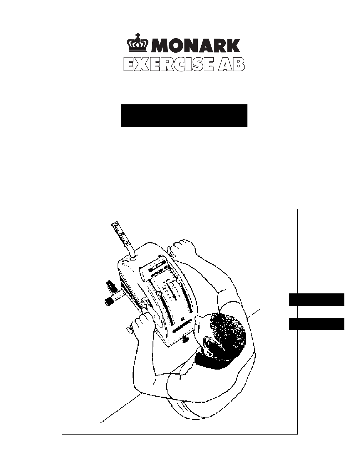
Rehab T rainer
881E
Svenska
English
Page 2

2
Page 3

3
CONTENTS
Assembly instructions...................................................................................................... 4
Calibration
............................................................................................................................................ 6
Operation instructions
................................................................................................... 7
How to replace batteries
............................................................................................. 11
Comparison of arm work to leg work
............................................... 12
References
............................................................................................................................................... 12
Congratulations on your decision to purchase a product
manufactured by Monark in Sweden. Monark has been
the world´s leading manufacturer of high quality ergometers and exercise cycles for more than 40 years.
English
Page 4

4
ASSEMBLY INSTRUCTIONS
The parts shown below are not assembled.
Transport
handle
Pedal,
right hand
Crank handle,
right hand
Supporting tube
Crank arm,
right hand
Crank handle,
left hand
Fig 1
Pedal,
left hand
Crank arm,
left hand
Hand guard
Hand guard
Page 5

5
Assemble supporting tube with two screws M6 x 27
and two spring washers. See fig 2.
Pull out the pin and assemble the transport handle.
Put the transport handle in its highest position when
the Rehab Trainer is moved on the transport wheels.
See fig 3.
Assemble crank arm marked R (Right) including two
star locks and bolt M8 x 40 on the right hand side.
Crank arm marked L (Left) including lock head and
bolt M8 x 40 to be assembled on the left hand side.
Pedals
Assemble the pedal marked R (Right) on the right hand
side. The pedal axle has a right hand thread and must
be threaded onto the crank clockwise.The pedal marked L (Left) to be assembled on the left hand side. The
pedal axle marked L has a left hand thread and must
be threaded onto the crank counter clockwise.
Crank handle
The crank handle markd R (Right) is to be assembled
on the right hand side with the hand guard placed on
the axle.The axle has a right hand thread and must be
threaded onto the crank clockwise.The crank handle
marked L (Left) is to be assembled on the left hand
side with the hand guard placed on the axle. The axle
has a left hand thread and must be threaded onto the
crank counter clockwise.
NOTE! The pedals or the crank handles can be assembled in three different positions on the crank arms. See
page 6, fig 7.
ASSEMBLY INSTRUCTIONS cont.
Transport handle
Pin
Crank handle, right
Marked R
Crank arm, right
Marked R
Pedal, right
Marked R
Transport wheels
Fig 4
Crank arm, left
Marked L
Pedal, left
Marked L
Crank handle, left
Marked L
Fig 2
Handguard
Fig 3
Page 6

6
CALIBRATION
Fig 6
Fig 5
Calibration is done at the factory. If you for some reason want to check the calibration, do as follows:
Tighten the brake belt through turning the control
knob so that the pointer goes up to about 25-50 Watt
at rotation of the crank.
Put the Rehab Trainer at the edge of a table as shown
in fig 5.
Loosen the screws for the clamping plate, so that the
end of the brake belt is loose. See fig 5.
Fasten a 2 kg weight (our Article No 9000-212) to the
brake belt. See fig 5. This weight should now be read
on the scale at 2 kp. See fig 6.
Should there be a deviation between the position of
the pointer and the 2 kp mark on the scale, adjust the
loading spring by turning the adjusting screw until the
correct position is obtained. See fig 5 and 6. Turn clockwise if the pointer is placed too high and turn counter
clockwise if the pointer is placed too low.
Remove the weight and fasten the brake belt with the
screw for the clamping plate so that the pointer does
not go below the zero (”0”) mark on the scale.
The height level of the cranks is adjustable when loosening the nuts according to fig 7. Set the crank arms
at the desired position and fasten with the nuts.
If the cranks are not in line, adjust these. Set first the
left hand crank straight upwards. Then loosen the right
hand crank by undoing the screw as per fig 7. Adjust
the position of the right hand crank so that it is in line
with left hand crank and fasten the screw.
Screw for
clamping plate
Resistance
belt
Adjusting
screw
Fig 7
Crank arm
screw
Nuts
Graduated
scale
3 different
positions
Page 7

7
Fig 9 Arm exercise with the er gometer hanging on wall bars.
OPERATION INSTRUCTIONS
Monark Rehab Trainer model 881E is an arm and leg
ergometer provided with a belt brake. The power can
be read in Watts at 50 pedal revolutions per minute.
Moreover, the work can be read in kilopondmeters
(kpm). The Rehab Trainer is also equipped with an
electronic meter, showing pedal revolutions per minute,
the total pedal revolutions and time function.
When cycling the test person puts supplies the flywheel
into a certain kinetic energy. This is braked by means
of a brake belt which runs around the bigger part of
the brake surface of the flywheel.
The workload is changed either by using another
pedalling speed or by increasing or decreasing the
tension of the brake belt against the flywheel by means
of the work load contol knob.
Fig 8 Arm exercise in a sitting position with the er g ometer
placed on a table
Graduated
scale
Control knob
for adjustment
of work load
Fig 12 Fig 10 Leg exer cise in a sitting position with the er gometer
placed on the floor.
Fig 11 Leg exercise in a lying position at the same level as the ergometer.
Page 8

8
The total work can be read in kilopondmeter. In our
example we have chosen 50 watt as work load. When
250 revolutions are finished, we can read the result that
the work is about 1500 kilopondmeter.
OPERATION INSTRUCTIONS cont.
Meter functions
The buzzer gives an audible signal after half the exercise time and when there are 30 seconds left. It gives
repeated signals for 20 seconds after the end of the preset time.
Fig 13
Fig 14
PEDAL REVOLUTIONS
25 50 75 100 125 150 175 200 225 250 275 300
kpm
25 75 150 225 300 375 450 525 600 675 750 825 900
50 150 300 450 600 750 900 1050 1200 1350 1500 1650 1800
75 225 445 675 900 1125 1350 1575 1800 2025 2250 2475 2700
100 300 600 900 1200 1500 1800 2100 2400 2700 3000 3300 3600
Chosen work load
Total pedal revolutions
Display
Buzzer
Hours
Minutes
Functions selector
Stop for buzzer
Time
Total pedal revolutions
Pedal revolutions/minute
Reset
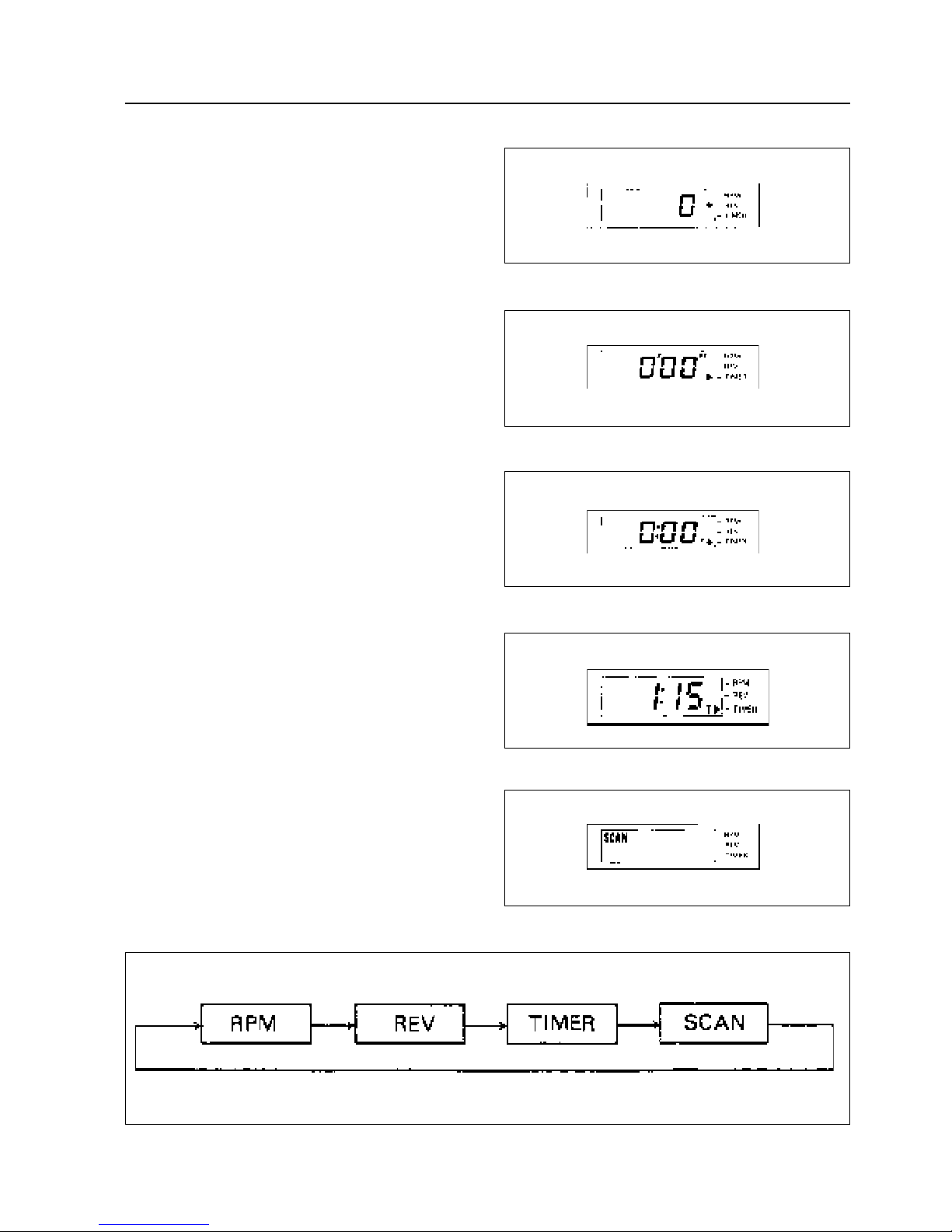
Start by pressing the button for function. Press as many
times as is necessary to get the marker on ”REV” according to fig 15. To reset, press the reset button so that
display according to fig 15 is shown.
Page 9

9
OPERATION INSTRUCTIONS cont.
Press the function button once so that the marker stands
at ”TIMER” according to fig 16. If the display is not
reset, press the reset button so that a display like fig 17
is shown. After 5 seconds the display changes automatically to fig 16.
Let´s imagine that you will exercise for 1 hour and 15
minutes. Press the buttons for hours and minutes, so
that a display like fig 18 is shown. The countdown
starts 5 seconds after the time has been entered.
When setting time exceeding one hour, the meter shows
time in hours and minutes but not in seconds, which
are then existing only in the computer. This means that
when the countdown starts after about 5 seconds, the
display shows 1.14 at the same time as the computer
invisibly, counts the remaining seconds up to 1 hour
and 14 minutes.
At time below one hour both minutes and seconds are
shown on the display.
Press the function button once, so that the display
shows ”SCAN”. See fig 19.
The displaying will now automatically change between
the function at intervals of 3.5 seconds.
Scan cycles through the functions as shown in fig. 20.
Fig 15
Fig 16
Fig 17
Fig 18
Fig 19
Fig 20
Page 10

10
OPERATION INSTRUCTIONS cont.
Fig 21
Fig 22
Table 1. Oxygen Comsumption (L/min) at Workloads Below the Anaerobic Threshold:
Work (Approx Watts) V02 Work (Approx Watts) V02
(kpm/min) (kpm/min)
150 24 .6 400 64 1.1
200 32 .7 450 72 1.2
250 40 .8 500 80 1.3
300 48 .9 550 86 1.4
350 56 1.0 600 96 1.5
When the marker stand at ”RPM” pedal revolutions
per minute are shown. Fig 21 shows 50 pedal revolutions per minute.
When the marker stands at ”REV” the toal number of
revolutions achieved during the exercise is shown. Fig
22 shows a total of 500 pedal revolutions.
5 minutes after the cyling is finished, the meter is automatically shut off.
After the exercise is finished, the registrated total number of pedal revolutions are kept in the meter.
If the exercise is stopped more than 5 minutes before
the exercise time setting, the remaining time – when
the meter is automatically shut off – will still be there,
when the meter is started over again.
As to resetting, please see figures 15, 16 and 17 at page
9.
WARNING! Do not expose the electronic meter to
direct sunlight or extremely high temperatures. Do not
use any dissolvents when cleaning but a dry cloth.
Handling
Work is started with a slack brake belt. Thereafter, the
belt should be stretched with the tensioning knob unteil the required workload is obtained. A metronome
will assist the subject in maintaining the porper rotational speed. As the belt and wheel get warmed up, the
friction will change, necessitating readjustment, especially if the trainer has been unused for any length of
time.
Published test protocols for the arm ergometer have
been limited. One of the few in print by Jones and
Campbell, recommended increments of 50 kp/min
(approximately 8 Watts) for their Stage 1 study. (5)
Page 11

11
HOW TO REPLACE BATTERIES
Remove the sliding lid and replace the batteries. Put
the sliding cover back in its position.
Fig 23
Fig 24
Fig 25
Page 12

12
COMPARISON OF ARM WORK TO LEG WORK
When comparing arm ergometry or arm exercise to
leg ergometry, there are several physiologic considerations. The maximum work that a muscle is able to perform is related to its size. Obviously, the muscle mass
of the arms is considerably smaller than the legs and
therefore the maximum work and maximum ozygen
consumption of the legs will be greater. Hershfield and
others added that the mechanical differences in the
shoulder and hip joints increase metabolic demands
when arm work is performed. (1)
Reybrouck and others found that at workloads below
the ”anaerobic threshole”, when adequate oxygen is
supplied to meet all the muscle´s requirements, the
oxygen consumption from arm work matches closely
the oxygen consumption during equivalent leg work.
(2) They noted that heart rate and ventilation were
higher during arm work at the same oxygen consumption in leg ergometry.
In rehabilitation or evaluation of disability, the expected sustained work capability of an individual is approximately 40% of maximum work and below the
anaerobic threshold. (3) To use the equivalent work
tables which have been published (reference 4), divide
the V02 at the subject´s workload by the patient´s
weight in kilograms. Divide this V02 ml/kg by 3.5.
This will give the equivalent METs and then evaluate
the tasks of which they are capable of performing at
that MET level.
REFERENCES
1. Hershfield S, et al. Relative effects on the heart by
muscular work in the upper and lower extremities.
Arch Phys Med Rehab. Pages 249-257, May 1968.
2. Reybrouck T, el al. Limitations to maximum oxygen uptake in arm, leg and combined arm-leg ergometry. J Appl Physiol 38:774-669, 1975.
3. Becklage MR. Organic or functional impairment.
Am Rev Resp Dis 129:S96-100, 1984.
4. Physician´s Handbook for Evaluation and Physical Fitness. Tennesse Heart Association, Physical
Exercise Committee, 1972, pgs 44-45.
5. Jones NL, Campbell EJM. Clinical exercise testing.
WB Saunders Publishing, Phila, PA. Page 86, 1975.
Page 13

13
Vi gratulerar till din nya motionsergometer.
Monark har i mer än 40 år varit en världsledande
tillverkare av ergometer- och motionscyklar med
mycket hög kvalité.
Svenska
INNEHÅLL
Monteringsinstruktion................................................................................................... 14
Kalibrering
............................................................................................................................................ 16
Funktionsbeskrivning
...................................................................................................... 17
Byte av batterier
.......................................................................................................................... 21
Page 14

14
MONTERINGSINSTRUKTION
Nedanstående detaljer är ej monterade.
Transporthandtag
Pedal,
höger
Vevhandtag,
höger
Stödrör
Vevarm,
höger
Vevhandtag,
vänster
Fig 1
Pedal,
vänster
Vevarm,
vänster
Sidostöd
Sidostöd
Page 15

15
Montera stödrör med två skruvar M6x27 samt två fjäderbrickor. Se fig 2.
Drag ut sprinten och montera transporthandtaget.
Transporthandtaget skall sättas i sitt högsta läge när
Rehab Trainern förflyttas på transporthjulen. Se fig 3.
Vevarm märkt R (Right) inkl två stjärnlåsklackar och
bult M8x40 monteras på höger sida. Vevarm märkt L
(Left) inkl låsklack och bult M8x40 monteras på vänster sida.
Pedaler
Pedal märkt R (Right) monteras på höger sida. Pedalaxeln är högergängad och skall gängas på veven i riktning medurs. Pedal märkt L (Left) monteras på vänster sida med sidostödet placerat på axeln. Axeln är
vänstergängad och skall gängas på veven i riktning
moturs.
Vevhandtag
Vevhandtag märkt R (Right) monteras på höger sida
med sidostödet placerat på axeln. Axeln är högergängad och skall gängas på veven i riktning medurs. Vevhandtag märkt L (Left) monteras på vänster sida med
sidostödet placerat på axeln. Axeln är vänstergängad
och skall gängas på veven i riktning moturs.
OBS! Pedaler eller vevhandtag kan monteras i tre olika
lägen på vevarmarna. Se sid 16, fig 7.
MONTERINGSINSTRUKTION forts.
Transporthandtag
Sprint
Vevhandtag,
höger
Märkt R
Vevarm, höger
Märkt R
Pedal, höger
Märkt R
Transporthjul
Fig 4
Vevarm, vänster
Märkt L
Pedal,
vänster
Märkt L
Vevhandtag,
vänster
Märkt L
Fig 2
Sidostöd
Fig 3
Sidostöd
Page 16

16
KALIBRERING
Fig 6
Fig 5
Kalibrering är gjord på fabrik. Vill man av någon anledning kontrollera kalibreringen, gör enligt följande:
Spänn upp bromsremmen genom att vrida åt belastningsratten, så att vid rotaion av veven visaren går upp
till mellan 25 och 50 Watt.
Placera Rehab-Trainern vid kanten av ett bord såsom
fig 5 visar.
Lossa skruvarna för klämplattan, så att stoppremmen
sitter löst. Se fig 5.
Fäst en vikt på 2 kg (vårt art nr 9000-212) i stoppremmen enligt fig 5. Denna vikt skall nu kunna avläsas på
skalan vid 2 kp. Se fig 6.
Stämmer inte visarens läge med skalans 2 kp markering, justera belastningsfjädern genom att vrida justerskurven för belastningsfjädern till detta stämmer. Se
fig 5 och 6. Vrid medurs om visaren står för högt och
vrid moturs om visaren står för lågt.
Ta bort vikten och fäst stoppremmen med skruv och
klämplatta i ett läge där visaren inte kan gå längre ner
än till 0 på skalan.
Vevarnas höjdläge är justerbart, när muttrarna enligt
fig 7 lossas. Ställ in vevarmarna i det gradtal som önskas och drag fast med muttrarna.
Om vevarna inte ligger i linje måste dessa justeras. Ställ
först in vänster vev rakt uppåt. Lossa därefter höger
vev genom att lossa skruven enligt fig 7. Justera högervevens läge, så att den ligger i linje med vänster vev
och drag fast skruven.
Skruv för
klämplatta
Stopprem
Justerskruv
Fig 7
Skruv för
vevarm
Muttrar
Gradtal
Tre olika
lägen
Page 17

17
Fig 9 Armträning med ergometern hängade i ribbstol.
FUNKTIONSBESKRIVNING
Monark Rehab Trainer modell 881E är en arm- och
benergometer försedd med broms vars effekt kan avläsas
i watt vid 50 pedalvarv per minut. Dessutom kan
arbetet avläsas i kilopondmeter (kpm). Rehab Trainern
är också utrustad med elektronisk mätare som visar
pedalvarvtalet per minut, pedalvarvtalet totalt samt en
tidsfunktion.
Genom cykling tillför testpersonen bromshjulet en viss
rörelseenergi som bromsas ut med ett bromsband som
löper runt större delen av bromshjulets bromsbana.
Ändringar av bromseffekten sker antingen genom
annan tramphastighet eller att med belastningsratten
öka eller minska bromsbandets spänning mot bromshjulet.
Fig 8 Armträning sittande med ergometern stående på ett
bord.
Graderad
skala
Belastningsratt
Fig 12 Fig 10 Benträning sittande med ergometern stående på
golvet.
Fig 11 Benträning liggande i samma nivå som
ergometern står placerad.
Page 18

18
Totala arbetet som utförs, kan avläsas i kilopondmeter.
I vårt exempel har vi valt 50 watt som belastning. När
250 pedalvarv avverkats, kan vi då avläsa att arbetet är
ca 1500 kilopondmeter.
FUNKTIONSBESKRIVNING forts.
Mätarens funktion
Summern avger en ton efter halva träningstiden och
vid 30 sekunder kvar samt avger upprepade toner under 20 sekunder efter den inställda tidens slut.
Börja med att trycka på knappen för funktion. Tryck
så många gånger som krävs för att få fram markering
Fig 13
Fig 14
PEDAL REVOLUTIONS
25 50 75 100 125 150 175 200 225 250 275 300
kpm
25 75 150 225 300 375 450 525 600 675 750 825 900
50 150 300 450 600 750 900 1050 1200 1350 1500 1650 1800
75 225 445 675 900 1125 1350 1575 1800 2025 2250 2475 2700
100 300 600 900 1200 1500 1800 2100 2400 2700 3000 3300 3600
Vald belastning
Totalt antal pedalvarv
Display
Summer Timmar
Minuter
Funktionsväljare
Avstängning för summer
Tid
Pedalvarv totalt
Pedalvarv/min
0-ställning
på ”REV” enligt fig 15. Om displayen inte är 0-ställd,
tryck på knappen för 0-ställning, så att registrering
enligt fig 15 visas.
Tryck en gång på knappen för funktion, så att markeringen står på ”TIMER” enligt fig 16. Om displayen
Page 19
19
FUNKTIONSBESKRIVNING forts.
inte är 0-ställd, tryck på knappen för 0-ställning, så att
registrering enligt fig 17 visas. Efter 5 sekunder växlar
registreringen automatiskt över enligt fig 16.
Vi tänker oss, att Du tänker träna i en timma och 15
minuter. Tryck på knapparna för timmar och minuter,
så att registrering enligt fig 18 visas. Nedräkningen
börjar 5 sekunder efter att tiden matats in.
Vi inställning på tid över en timma,visar mätaren tiden i timmar och minuter men inte i sekunder, som då
bara finns i datorn. Detta innebär, att när nedräkningen startar efter 5 sekunder, så visar displayen 1.14 samtidigt som datorn osynligt räknar återstående sekunder till en timma och 14 minuter.
Vid en tid under en timma visas både minuter och
sekunder på displayen.
Tryck en gång på knappen för funktion, så att dispalyen visar ”SCAN”. Se fig 19.
Växling kommer nu automatiskt att ske mellan funktionerna med 3,5 sekunders mellanrum.
Funktionerna visas alltid på displayen i den följd som
fig 20 visar.
Fig 15
Fig 16
Fig 17
Fig 18
Fig 19
Fig 20
Page 20

20
När markeringen står på ”RPM” visas pedalvarvtal per
minut. Fig 21 visar 50 pedalvarv per minut.
När markeringen står på ”REV” visas totala antalet
pedalvarv under träningen. Fig 22 visar 500 pedalvarv.
5 minuter efter avslutad träning stängs mätaren automatiskt av.
Efter avslutad träning ligger registrerat totalt antal pedalvarv kvar i mätaren. Om träningen avslutas mer än
5 minuter före inmatad träningstid, kommer den återstående tiden – när mätaren automatiskt sängs av – att
ligga kvar när mätaren startas på nytt.
Beträffande 0-ställning, se fig 15, 16 och 17 på sid 19.
VARNING! Utsätt inte mätaren för direkt solljus eller
extremt höga temperaturer. Använd inga lösningsmedel vid rengöring, utan endast en torr trasa.
OPERATION INSTRUCTIONS cont.
Fig 21
Fig 22
Page 21

21
BYTE AV BATTERIER
Tag loss det skjutbara locket och byt ut batterierna.
Sätt åter locket på plats.
Fig 23
Fig 24
Fig 25
Page 22

22
Page 23

23
Page 24

24
SE-780 50 Vansbro, Sweden. Tel +46 (0)281 594940. Fax +46 (0)281 71981
e-mail: info@monarkexercise.se www.monarkexercise.se
 Loading...