

Monarch Nova-Strobe BBX, Vibration Strobe VBX, Nova-Strobe DBX, Phaser Strobe PBX Replacement Manual
Page 1
the professional’s choice
Nova-Strobe Battery Replacement
for models: Nova-Strobe BBX, Nova-Strobe DBX, and Phaser Strobe PBX, Vibration Strobe VBX
Before you open the case, know that during the reassembly there are multiple points that
need to align correctly to close the case securely.
Some of them include:
• Display board sits in groove
• DC Connector spans both case halves
• Mounting T-nut sits in slot as shown
• Lanyard knot surrounds screw standoff and protrudes through the notch in the case
• Trigger sits in case brackets with wires tucked out of the way
• PCB aligns in a retaining groove
• Battery holders (2) nests in brackets, there is a right and wrong way to insert them
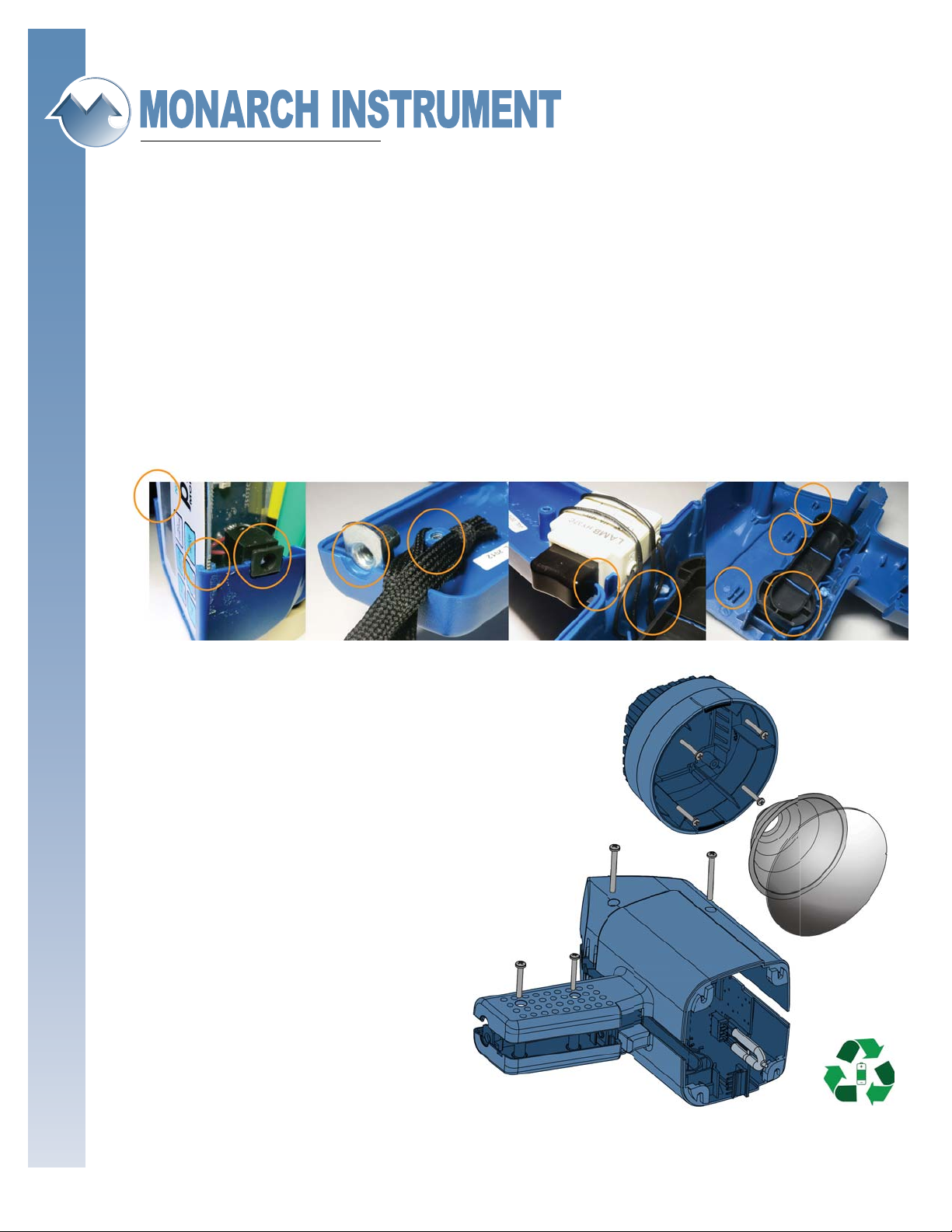
Taking the unit apart is the easy part . . .
To do this, [A] remove the lens by
separating the two tabs that hold
it in place. Put a piece of tape on
the side of the lens that faces out
so it can be installed correctly. Slide
the refl ector [B] and lamp out as
detailed in the Lamp Replacement
section of your manual. This will
expose four screws [C] that must
be removed so the refl ector hous-
ing can be removed from the main
body. There are then four additional
screws [D1] & [D2] in the case
halves opposite the input and
output jacks that must be removed.
The case halves can now be separated,
exposing the batteries. They should
be sent to a recycling center or
returned to Monarch for disposal.
[D2]
[D1]
[C]
[B]
[A]
15 Columbia Drive • Amherst, New Hampshire • USA 03031-2334
TEL: 603-883-3390 • FAX: 603-886-3300 • www.monarchinstrument.com • sales@monarchinstrument.com
Page 2
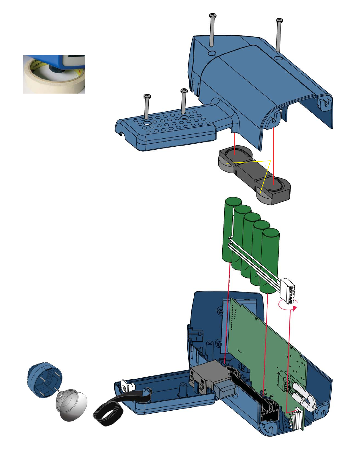
[D1]
Placing the left side of the case
on a roll of tape or other lift
will prevent the speed knob
from pushing the PCB out of
the retaining slots when
aligning all.
[D2]
Replace the battery.
Ensure that the replacement battery is plugged
into the PCB fi rmly. Carefully place the right half
(1055-4241-111) onto the left (1055-4242-111).
Align the display board [F], battery [G], and main
PCB [H] into the slots provided in the case. Align
the display and battery fi rst, then from the front
of the unit, guide the PC Board into the retaining
slots with a wooden stick. Ensure the trigger wires
[I] and DC Jack [J] are properly in place.
[D1]
Top half of the
Battery Holder sits
in the right side case.
Note the position of
the cradle guides
Fasten both halves using two 2” self tapping
screws [D] (1053-3328-001) through the body of
the right half. Do not over tighten screws.
Gently pry apart case halves at the base of the
handle and insert tee nut [K] (1053-0270-001)
into slot in left handle.
Slip knotted end of wrist strap [L] (3051-2000-
015) over left half handle standoff and through
slot provided.
Carefully press case handles together, ensuring
the wrist strap fi ts into the notch provided and no
wires are pinched between the case halves.
Re-attach the refl ector housing.
Do not over tighten screws [C], [D1], [D2].
[K]
[F]
[J]
[I]
[G]
[H]
Monarch Instrument © 2018
Nova-Strobe Battery Replacement 8/2018 v3.0
[L]
 Loading...