

Page 1
MONARCH INSTRUMENT
Instruction Manual
Printed in the U.S.A. © Monarch Instrument 2002 all rights reserved
1071-4800-121
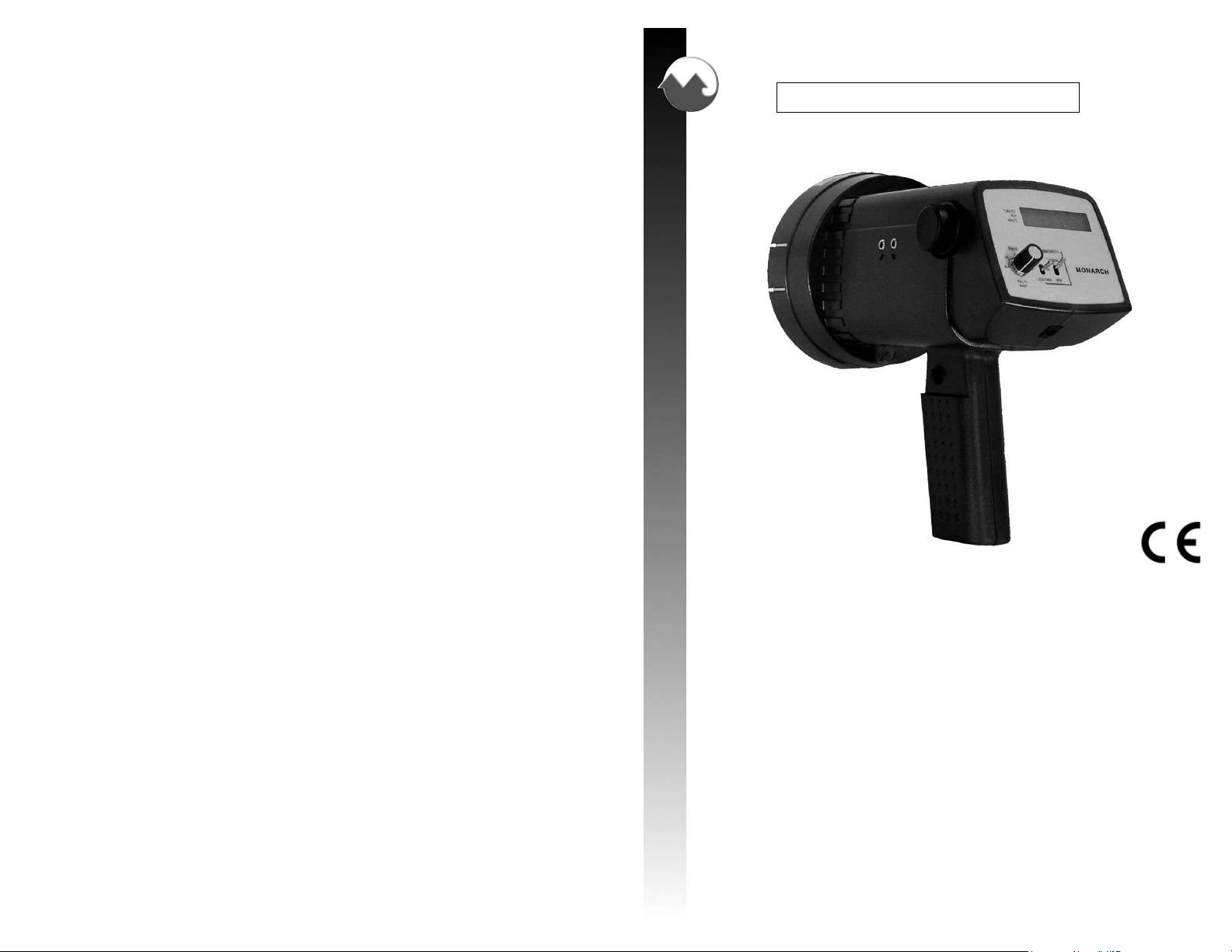
Vibration Strobe
15 Columbia Drive
Amherst, NH 03031-2334 USA
Phone: (603) 883-3390
Fax: (603) 886-3300
E-mail: support@monarchinstrument.com
Website: www.monarchinstrument.com
Page 2

Safeguards and Precautions
1. Read and follow all instructions in this manual carefully, and retain
this manual for future reference.
2. Do not use this instrument in any manner inconsistent with these
operating instructions or under any conditions that exceed the
environmental specifications stated.
3. Use of this product may induce an epileptic seizure in persons prone
to this type of attack.
4. Objects viewed with this product may appear to be stationary when
in fact they are moving at high speeds. Always keep a safe distance
from moving machinery and do no touch the target.
5. There are lethal voltages present inside this product. Refer to the
section on Lamp Replacement before attempting to open this product.
6. The ventilation holes must remain unrestricted (well exposed) when
the unit is in operation to allow heat to escape.
7. Do not allow liquids or metallic objects to enter the ventilation holes
on the stroboscope as this may cause permanent damage and void
the warranty.
8. Do not allow cables extending from unit to come into contact with
rotating machinery, as serious damage to the equipment, or severe
personal injury or death may occur as a result.
9. Do not direct strobe flash toward certain data collectors, as it may
temporarily interrupt data collector operation, and could result in loss
of stored data.
10. This instrument may not be safe for use in certain hazardous
environments, and serious personal injury or death could occur as a
result of improper use. Please refer to your facility’s safety program
for proper precautions.
11. Do not attempt to operate the unit while charging. To do so may
cause permanent damage to the charger and the strobe light.
PRODUCT WARRANTY POLICY
SELLER warrants the Vibration Strobe to be free from defects in workmanship on all parts
except as noted below, for a period not to exceed 12 months from date of shipment to
BUYER. The warranty period for battery defects and flash tube defects shall be 6 months
from date of shipment to BUYER. SELLER’s entire liability and BUYER’s sole and exclusive
remedy resulting from any defect in workmanship or material in the hardware product covered
by this limited warranty shall be limited to and fully discharged by the SELLER’s option of
replacement or repair of such item without charge. The limited warranty provided in this
clause is in lieu of all other warranties, expressed or implied, arising by law or otherwise.
ALL IMPLIED WARRANTIES OF MERCHANTABILITY AND FITNESS FOR A PARTICULAR
PURPOSE ARE EXCLUDED. This limited warranty shall not be modified except by an
arrangement signed by both parties specifically referencing this clause.
Product failure or damage caused by misuse or abnormal operating conditions are not
covered by this warranty. If the malfunction, or a portion thereof, is determined by SELLER
to have been caused by misuse or abnormal conditions of operation, or otherwise is not a
warranty item, an estimate of cost to repair will be submitted to the BUYER for approval
before any such repairs are performed.
NO OTHER WARRANTY IS HEREBY EXPRESSED OR IMPLIED. IN NO EVENT SHALL
SELLER BE LIABLE FOR ANY SPECIAL, INDIRECT, INCIDENTAL, CONSEQUENTIAL,
OR PUNITIVE LOSSES OR DAMAGES (INCLUDING, BUT NOT LIMITED TO, LOSSES
OR DAMAGES FOR ANY LOST PROFITS OR LOST DATA) AS THE RESULT OF ANY
BREACH OR DEFAULT BY SELLER WITH RESPECT TO THE HARDWARE OR
SOFTWARE, EVEN IF SELLER HAS BEEN ADVISED OR MADE AWARE OF THE
POSSIBILITY OF ANY SUCH LOSSES OR DAMAGES AND REGARDLESS OF WHETHER
THE CLAIM IS BASED ON CONTRACT, TORT, STRICT LIABILITY, OR OTHER THEORY
OF LIABILITY.
Liability under this warranty is limited to servicing and adjusting the instrument returned to
Monarch Instrument factory, with transportation charges prepaid by the BUYER. THE USER
SHOULD NOT UNDERTAKE ANY STROBE REPAIRS. OPENING THE CASING WILL
CAUSE THE WARRANTY TO BE NULL AND VOID.
If a malfunction develops, notify the Customer Support Department of Monarch Instrument,
or its representative in your area, giving details of the problem, and the name, model and
serial number of the unit. Upon receipt of this information, service data or shipping instructions
will be provided. Please do not ship product prior to contacting Monarch Instrument, or its
local representative, for a Return Material Authorization (RMA) Number, to insure
proper handling.
12. This product contains sealed lead acid batteries which must be
disposed of in accordance with Federal, State, & Local Regulations.
Do not incinerate. Batteries should be shipped to a reclamation facility
for recovery of the metal and plastic components as the proper method
of waste management. Contact distributor for appropriate product
return procedures.
13. This instrument is not user serviceable. For technical assistance,
contact the sales organization from which you purchased the product
or Monarch Instrument directly.
Page 3
DECLARATION OF CONFORMITY
TABLE OF CONTENTS
TABLE OF CONTENTS
INTRODUCTION ....................................................................................... 1
As Manufacturer:
Monarch Instrument
Division of Monarch International Inc.
15 Columbia Drive, Amherst NH 03031 USA
declares under Monarch’s sole responsibility that the product:
Name: Vibration Stroboscope
Model: VB 115/230
to which this declaration relates is in conformity with the following standards:
EMC: EN50082-2:1995
EN55011:1991 Group 1, Class A
EN61000-4-2
ENV50140
EN61000-4-4
ENV50142
ENV50141
and therefore conforms with the requirements of Council Directive
89/336/EEC relating to electromagnetic compatibility. Retlif Testing
Laboratories performed the testing of this product. (Report No R-2700N).
27th March 1996
Manufacturer (Amherst, NH) Alan Woolfson, VP Engineering (Authorized Signature)
PREPARATION FOR USE ........................................................................ 2
OPERATION ............................................................................................. 3
MEASURING RPM WITH THE Vibration Strobe ....................................... 4
BALANCING AND PHASE MEASUREMENT ........................................... 4
PHASE ANALYSIS ................................................................................... 6
MOTION STUDIES ................................................................................... 7
POWER REQUIREMENTS AND BATTERY CHARGING ........................ 8
LAMP REPLACEMENT ............................................................................. 8
REPAIR/SERVICE/PARTS ..................................................................... 10
SPECIFICATIONS
Flash Rate Range: 100-12,000 FPM (Flashes Per Minute)
Locking Range: Wide Mode: 600 to 10,000 RPM
Narrow Mode: 200 to 8,000 RPM
Accuracy: ± 1 FPM (RPM)
Resolution: 1 FPM
Display: 5-Digit Liquid Crystal Display, Low Battery Indication
Input: Connector: 3.5 mm Stereo Plug
2.5 to 12 volt pulse in External (EXT) mode
100mV/g accelerometer in Tracking (LOCK/TRACK) mode,
externally powered
Output: Connector: 3.5 mm Mono Plug
Approx 6 Volt positive pulse
Power: 6.0 Vdc, Internal Rechargeable Sealed Lead Acid Battery
Charger: 115 Vac (Optional 230 Vac)
Operating Time: In excess of 60 minutes at 1800 FPM (on full charge)
Flash Duration: 30 microseconds
Flash Tube (Lamp) Life: 100 million flashes
Operating Temperature: 0-40° C (May be operated for short time periods, slightly beyond stated
temperature range.)
Weight: 2.5 lbs.
Page 4

INTRODUCTION
The Vibration Strobe is a truly portable, battery-operated stroboscope that is suited for a wide range
of industrial, institutional, and educational applications, and is able to interface with several of the
Vibration Data Collectors that are currently available. Several interface cables are available. Sturdy
and compact, the strobe can be operated anywhere in the plant or field to permit visual inspection
(freeze motion), and digital measurement of rotary, reciprocating, or linear motions of various
equipment while it is in operation.
The Vibration Strobe has a special “tuning” circuit that allows it to track vibration transducer
(accelerometer) signals. This capability makes it different from general-purpose strobe lights. It
also has a Narrow and Wide Bandwidth filter selection to discriminate fundamentals from harmonics.
The Narrow Bandwidth filter limits the influence of harmonics around the selected frequency,
providing a more stable phase reading.
The Vibration Strobe requires an input signal to synchronize the flash rate with an external source,
typically a vibration transducer in the tracking mode or optical pickup in the external mode. This
signal is applied, using a special cable, to the Input (! pointing into socket) jack connector on the
side of the strobe light. The Vibration Strobe generates a tachometer signal that is on the Output ("
pointing away from socket) jack. Information about the use of these signals is given in other sections
of this manual. Special adapter cables are available to suit several commercially available
Vibration Analyzers.
The Vibration Strobe is ideally suited for:
1. Balancing
2. Inspection of High Speed Rotating Parts
3. Motion Analyses, or Phase Measurement
4. Over speed Trip Tests
5. Online coupling Inspections
The Vibration Strobe can also be used as a highly accurate, remote electronic digital tachometer for
direct measurement of RPM (speed) without special reflective tape or markings. RPM results are
updated and displayed approximately every 1 second on a 5-digit LCD display.
The display panel consists of a backlit liquid crystal display with five alphanumeric digits (see Figure
1). Below the display is a knob that controls the phase shifting, the Mode Selector Switch and the
Bandwidth Switch.
REPAIR/SERVICE/PARTS
Repair:
In accordance with the warranty and replacement provisions, the user ordinarily would undertake
no strobe repairs. Possible exceptions involve minor malfunctions, i.e., cables, plugs, and
attachment items.
Assembling the Vibration Strobe is a critical procedure. It should NOT be dismantled. However,
the reflector lens is removable for lamp replacement. Refer to the section on Lamp Replacement
for instructions.
Service:
Notes should be kept regarding field troubles, whether or not any of the equipment is returned at
that time. A brief history or record of symptoms, or of pre-fault behavior is of substantial aid to the
factory. This is especially true of intermittent malfunctions that might call for a schedule of extended
scrutiny at the repair site.
Disposal:
Prior to disposing of this product, the user must remove the sealed lead acid batteries. To do this,
remove the lens as detailed above in lamp replacement, remove the reflector and lamp. This will
expose 4 screws that must be removed so the reflector housing can be dismantled. There are four
additional screws in the case half opposite the input and output jacks that must be removed. The
case halves can now be separated, exposing the batteries. Remove the cables from the batteries and
place tape over the battery terminals to prevent them from shorting. The batteries should be sent to
a recycling center or returned to the factory. The rest of the parts may now be disposed of.
Parts:
The following parts are available for field replacement, and can be ordered directly from
Monarch Instrument.
Model Description
CC-7 Latching Carrying Case for Strobe with provision for accessories
FR-3CE Fast Charger, 115Vac, 50/60Hz (3 hour)
FR-4CE Fast Charger, 230Vac, 50/60Hz (3 hour)
L-1903 Vibration Strobe replacement lamp (flash tube)
50192 Cable, BNC to miniature phone jack, External trigger input
Figure 1 Display Panel
1
10
Page 5
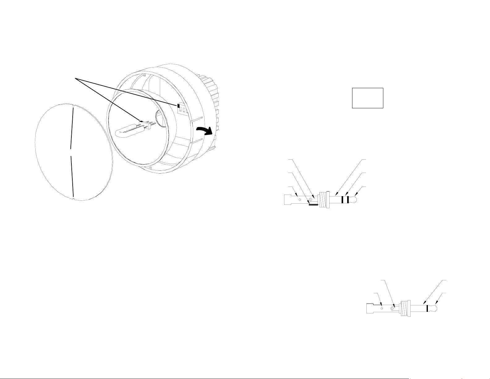
3. The lamps are polarized and must be put into the socket matching polarity. Using a lint
free cloth, match up the red dot on the plug with the red dot on the socket and
gently rock the lamp back and forth while pushing it into place (see Figure 5). Make sure
the lamp is in straight and centered in the reflector hole.
CAUTION: Do NOT allow the reflector to contact the lamp.
Red Dots
Notches
Figure 5 Lamp Replacement
4. Reinstall the reflector and then position the front lens in place matching up the notches on
the lens with the two small tabs on the housing to prevent lens rotation (see Figure 5).
Push the tabs on the front rim outward and press the lens into place.
PREPARATION FOR USE
The Vibration Strobe is a portable lightweight strobe flash unit with internal battery that will flash for
more than 1 hour at 1800 FPM (Flashes Per Minute) before recharging is required. The unit should
be fully charged prior to each use. See the Power Requirements and Battery Charging section later
in this manual for details.
The unit may be either hand-held, or mounted to a tripod or other user-supplied bracket using the
1/4" - 20 UNC bushing at the base of the handle.
The strobe has input and output jacks on the left side of the stroboscope (see Figure 2). These jacks
accept 3.5 mm plugs (input – stereo, output – mono).
! !! !
! !
! !! !
""
!!
"
!
""
!!
Out In
Figure 2 Input/Output Jacks
Input
The input ring is for the accelerometer input. The accelerometer must be powered externally and
this input is decoupled internally, so that the positive or signal from the transducer can be applied
Signal Input
Sensor Input
Common
(GND)
Figure 3 Input Connector Connection Detail
minute). There is typically a 5 µsec delay from trigger input to flash. The trigger source should
provide a pulse with a minimum duration (width) of 20 µsec in the range 2.5 to 12 volts dc.
Output
In the Internal (INT) mode, the output provides a TTL compatible pulse from the strobe’s internal
oscillator in synch with the flash. In the External (EXT) mode, the output pulse mimics the input
pulse. This output pulse may be
used to trigger a second stroboscope
synchronously to illuminate larger
areas. In the Tracking (LOCK/
TRACK) mode, this output is a pulse
at the tracking or lock frequency, at
the strobe flash rate, and may be
phase shifted ±180° from the
reference point.
Common
(GND)
Sensor Input
(100 mV/g)
Signal Input
(TTL Pulse)
Signal Input
Common
(GND)
Figure 4 Output Connector Connection Detail
directly. The unit is optimized
for 100mV/g accelerometers,
but any signal above 5mVac will
activate the unit.
The input tip is for an external
digital signal from a remote
sensor or another strobe. The
range for triggering is from 0
flashes per second to 200 flashes
per second (12,000 flashes per
Common
(GND)
Signal Input
9
2
Page 6

OPERATION
To turn on the stroboscope, depress and hold the trigger. When the strobe is powered up in the
Internal (INT) mode, it will begin flashing immediately. The trigger may be locked in position using
the side-locking button. To lock the trigger on, hold the unit in the right hand, depress the trigger as
far as it will go, and then use your thumb to press the locking button. You may release the trigger
and the trigger will be held in place. To release the trigger lock, simply depress the trigger and
then release.
There are three Operating Modes that are controlled by the Mode Selector Switch at the front of the
unit. The Operating Modes are:
EXT: External - an external tachometer signal (TTL level pulse) controls
the flash rate, i.e. an optical sensor or second strobe.
INT: Internal - the internal oscillator controls the flash rate
LOCK/TRACK: Locking - when properly set, the vibration transducer (accelerometer)
controls the flash rate
Internal Mode – Standard Strobe Operation
In the Internal Mode the stroboscope generates its own signals and functions like an adjustable
stroboscope. The strobe is in the Internal Mode when the Mode Selector Switch is set to INT.
To operate in the Internal Mode:
1. Push the Mode Selector Switch to the INT (Internal Mode) position.
2. Depress and hold the trigger. The unit will begin to flash at the rate displayed on the LCD
display until the trigger is released.
3. Turn the control knob, located on the left side of the strobe to adjust the flash rate.
4. For continuous operation, squeeze the trigger once again, then depress the small “trigger
lock” button (just above the trigger, on the side of the unit) and the unit will continue to
flash with finger-free operation until the trigger is depressed again, which releases
the lock.
External Mode
In the External Mode the flash rate is a function of the input signal, and the user cannot make flash
rate adjustments. This mode is used to synchronize the flash to an external event (for example,
from an optical sensor) to stop or freeze motion. The flash will be triggered on the rising edge of the
external input pulse. The strobe is in the External Mode when the Mode Selector Switch is set to
EXT. The LCD will display the current Flash Rate.
Locking Mode
In the Locking Mode the vibration transducer (accelerometer) controls the flash rate. The strobe
is in the Locking Mode when the Mode Selector Switch is set to LOCK/TRACK.
Prior to setting the LOCK/TRACK mode, the strobe MUST be operated in the Internal
mode. The accelerometer must be properly connected and powered, usually by the external Vibration
Analyzer, and must be mounted in place. Special cable assemblies are available for several
commercially available Vibration Analyzers, or you may “steal” the accelerometer signal and feed
it into the strobe input as detailed above.
Once set up, you have to tune the strobe to set the center frequency of the filters to work with the
accelerometer. Using the Internal mode, adjust the flash rate of the strobe to stop motion of the
target of interest. Switch the Mode Selector Switch to LOCK/TRACK, and the strobe will now use
the signal from the accelerometer to control the flash rate.
3
POWER REQUIREMENTS AND BATTERY CHARGING
The Vibration Strobe has internal rechargeable batteries and can operate continuously in excess of
60 minutes at 1800 flashes per minute. The strobe has a protection feature to prevent it from
operating if the battery charge becomes too low. All decimal points on in the LCD display indicate
this condition. When this occurs, the battery is in need of recharging. The actual operating time of
the battery depends on the flash rate and duty cycle of operation.
NOTE: Do not attempt to operate the unit while charging. To do so may incur permanent damage
to the charger and the stroboscope.
The unit may be recharged at any time. You do not need to wait until the low battery condition is
indicated.
To charge the battery:
1. Release the trigger so the strobe is off.
2. Plug the recharger cable into the recharger socket (located below the display panel behind
the handle).
3. Plug the recharger into a mains wall outlet.
CAUTION: Use of rechargers other than the one supplied (FR-3A for 115 Vac or
FR-4 for 230 Vac) may damage the stroboscope and void
the warranty.
4. Press the black button on the front panel of the supplied recharger to begin a charge cycle.
The red LED “charge light” on the panel will illuminate.
The recharger will fast charge the batteries for up to 5 hours (typically 3½ - 4 hours). Once the fast
charge is completed, the recharger will trickle charge the batteries (as indicated by the red LED light
turning off). The unit may be left on charge overnight, and it requires 14 hours to reach a full
charge, from a low battery condition. The unit may be left on charge indefinitely.
The battery voltage can be measured at the charger socked on the strobe using a high impedance
voltmeter. A fully charged set of batteries should measure around 6.6 Vdc.
LAMP REPLACEMENT
WARNING: Before attempting to remove the lamp, make sure the stroboscope is
turned off and that the battery recharger and all other cabling are
disconnected from the unit. Allow the lamp to cool waiting at least
1 minute.
The stroboscope is designed to discharge the internal high voltages within 30 seconds. However,
caution should be exercised when replacing the lamp.
The lamp can be replaced by using just a pocket screwdriver. It is not necessary to remove any
screws to replace the lamp. A new spare lamp is supplied with each new Vibration Strobe Kit.
To change the lamp:
1. Push apart the two tabs on the side of the reflector housing and remove the front lens
using a small screwdriver to help pry one tab and lift the lens. Take care not to pry the tab
any more than is necessary to free the lens. The reflector is held in place by the front lens
and will come loose, but is not necessary to remove the reflector.
2. Hold the lamp with a cloth between your forefinger and thumb and rock it back and forth
gently while pulling out. Do not attempt to rotate the lamp. The lamp is socketed and
will come out easily when pulled.
WARNING: Do NOT touch the new lamp with bare fingers.
8
Page 7

Checking for unbalance:
1. If the vibration transducer is moved from the vertical position on the bearing to another
radial position, the reference mark will move to the new position if there is a significant
amount of unbalance. The reference mark will follow the vibration transducer around the
clock only if the once per turn vibration is caused by unbalance.
Checking for alignment:
1. Alignment checks can be made by moving the vibration transducer to each end of the
machines in a train. The vibration transducer is positioned axially at these locations for
these measurements. Keep track of the phase for each measurement location.
2. As the vibration transducer is moved to each location, it’s direction keeps changing from
North to South, for example. When it changes direction, phase will shift from 12:00
o’clock to 6:00 o’clock.
3. If you move across a coupling and phase does not change as expected, a misalignment
condition can be the cause.
MOTION STUDIES
The Vibration Strobe can be a useful tool to determine how a mechanical support or a piping system
is moving. It allows the user to find points of maximum motion as well as minimum motion. This is
important if a new pipe hanger is to be installed or if a brace is going to be added to dampen a
vibration condition.
For these tests the strobe light should be set on a tripod. A long cable will be needed for the sensor.
The sensor should be mounted on a magnetic base.
Follow the same 5 steps outlined in the previous section for General Preparation for phase analysis,
and then follow these steps:
1. Mark the piping system off in given intervals and note the location of supports or hangers.
For example, use 6-foot intervals. Draw a simple diagram on paper.
2. Start at the machine end, adjust the strobe light to running speed, and note the phase
reading using the clock face method. (For reference, adjust the phase marker to the 12:00
o’clock). Move the vibration transducer to each location, noting the phase reading
at each.
NOTE: Do not move the strobe light, just the vibration sensor. Do not change the Phase Angle
control knob after the initial reference has been set.
3. The phase markings should “walk” around the clock face as the sensor is moved to each
location. Each time the marking is at or near 12:00 o’clock, the motion is at or near
maximum and is in phase with the reference point. Each time the marking is at or near
6:00 o’clock, the motion is at or near maximum in the opposite direction and is out of
phase with the reference point.
The Narrow and Wide Bandwidth selector on the strobe’s front panel can be used to optimize its’
ability to lock onto the vibration signal at any speed. The Wide bandwidth will allow the strobe to
track the signal over a fairly wide range of speed change and should be used when tracking the
fundamental frequency (in simple systems).
On machines such as a gear drives, reciprocating engines, or any drive with multiple fundamental
frequency excitation, the strobe could encounter difficulty tracking the designated signal, due to the
tracking filter’s normal bandwidth. If substantial levels of multiple fundamental frequencies, or
fundamentals with harmonics occur within a selected bandwidth, the shaft reference may appear to
oscillate, or drift substantially, when viewed with the Vibration Strobe. Also, if the accelerometer
cannot be positioned on the primary point of interest, a fundamental frequency of something other
than that of the primary point of interest may be predominant. In these cases, use the Internal (INT)
mode and flash rate adjust to stop the motion of the primary point of interest, switch the Bandwidth
switch to Narrow, and then switch to the Locking (LOCK/TRACK) mode. The filter is far more
sensitive and will better be able to discriminate the required signal. However, it will not be able to
track over widely varying speed changes, which will require retuning in the Internal (INT) mode.
After the image has been locked and the Narrow or Wide Bandwidth has been optimized for the
speed and/or background noise on the sensor signal, the Phase knob can be used to adjust the phase
of the output pulse (and image) - refer to the Phase Analysis section later in this manual for adjusting
the Phase Angle control.
MEASURING RPM WITH THE Vibration Strobe
To read and measure RPM (speed) with the Vibration Strobe, select a permanent or semi-permanent
object or mark on the shaft to use as a visual reference. Most technicians choose to select an
unopposed shaft keyway, or other marking on the shaft, that is not duplicated on the opposite side
(180 degrees) of the shaft. If it is possible to stop the machine, mark the shaft with a center punch,
paint or permanent marker, liquid correction fluid, etc. When marking, it is a good idea to use
marks on the shaft 180 degrees apart, such as a horizontal line (-) at one point, and a vertical line (I)
180 degrees away. This will give an indication of a “+” when the flash rate (and LCD display) is at
two times actual running speed. This serves as a useful indicator.
It is suggested that the shaft mark/object should be observed at as much of a 360 degree rotation as
possible, however, normally a range of 180-200 degrees is sufficient. After placing the Mode
Selector Switch to INT, direct the flash toward the mark/object on the shaft. If the speed of rotation
is within the range of the strobe, start at the highest flash rate and adjust the flash rate slower until a
single image of the dedicated reference is observed. Note that at a flash rate twice the speed of the
image, that two images may be observed 180 degrees apart from each other. As you near the
correct speed you will see 3, 4 or more images at harmonics of the running speed. The first single
image you observe should be the true running speed. To verify this, simply slow the flash rate to half
of what was noted at one times speed. A single image should again appear. Readjust the flash rate
again, as closely as possible back to running speed, the next higher single image. As the mark is
locked-in, the LCD display will read out the true RPM (speed) of the machine part being observed.
BALANCING AND PHASE MEASUREMENT
The Vibration Strobe contains an internally tuned filter that is incorporated in a phase shifting
network, which allows the shaft reference mark to be directed at any convenient location on the
machine while balancing or performing motion studies (phase measurement) along a machine’s
casing or along a machine train. Examples of a convenient location are the machine’s horizontal
split line, top or bottom dead center, or the plane of the reference transducer.
NOTE: It is advisable to “LOG” this reference location, so that it may be utilized in future studies
or balancing procedures.
7
4
Page 8

To set-up for balancing or phase measurement, a data collector or vibration analyzer must be used
that is capable of interfacing with the Vibration Strobe. The instrument must then be set up to obtain
and record the phase information supplied to it from the strobe and the reference transducer.
As a general set-up guideline for the data collector or analyzer, in order to be triggered properly and
to read phase properly, check the following:
1. Set the instrument to accept an external tachometer trigger signal. The strobe light will
provide this signal.
2. Set the frequency range for order analysis (10 orders full scale works best). This insures
the 1X frequency will be centered in the 1X (first order) filter which is a must for repeatable
phase measurements.
3. Set the instrument to display averaged spectrum and phase data (4 or 8 averages).
4. Set transducer power to On.
NOTE: Application Notes are available for some data collectors that describe their particular set-
up configurations. Check the Owners Manual for your data collector for proper setup
configurations.
Connect the proper interconnect cable between the strobe and the data collector or analyzer. See
wiring diagram to build the cable. The Input (Up Arrow) and Output (Down Arrow) jacks are
located on the left side of the strobe. Connect the vibration transducer (this may be a separate cable
or an integral cable) to the strobe cable.
NOTE: The vibration transducer provides the signal the strobe uses as a phase trigger source and
therefore is the input to the strobe. The vibration transducer also provides the vibration
signal to the data collector or analyzer. The interconnect cable provides a “TEE” connection
to both. The strobe provides the phase referenced tachometer signal (output) which is
used as an input to the data collector or analyzer for triggering.
Now you are ready to go to work!
Follow the operating instructions outlined at the beginning of this section for tuning the strobe to 1X
running speed. After the reference mark has been “frozen” (as nearly as possible, but slight rotation
is acceptable), place the Mode Selector Switch in the LOCK/TRACK position. The flash rate is
now derived from the vibration transducer. Phase information is only valid when operating in
the Locking (LOCK/TRACK) mode.
Select the Phase Angle orientation that is desired (0-360 or ±180 degrees) by pulling or pushing the
Phase Angle control knob. Using the Phase Angle control knob, position the reference mark to a
“convenient viewing location”. The data collector can now be employed to receive and process the
phase information as supplied to it by the strobe and the transducer. After the information is received,
simply release the trigger on the strobe, proceed to the next point, and then repeat the process.
NOTE: The trigger must stay depressed until the data collector or analyzer is through processing
the data.
For certain data collectors that do not provide constant power out to transducers that so
require, it may be necessary to command the analyzer to begin taking the data before the
phase image becomes stable enough to allow it to be placed at a reference location. It
may also be noted that slight adjustment of the Phase Angle control knob may be required
before each measurement, to assure that the reference location is repeated.
If the data collector you are using does not respond to the phase reference signal supplied to it by
the strobe, it is possible that the Trigger Set-up in the data collector may be reversed. If so, change
the set-up from “positive” trigger slope to “negative”, or vice versa, and try again.
When the strobe is tuned in the Internal (INT) mode, and then switched to LOCK/TRACK, the filter
in the strobe will track slight changes in speed. If the speed changes too much or too fast, the strobe
will lose LOCK/TRACK and stop flashing. It will be necessary to switch back to Internal (INT)
mode and repeat the adjustments. Also, try switching the Narrow and Wide Bandwidth switch to
optimize results. Generally, the Wide Bandwidth will give best tracking results but the Narrow
Bandwidth will give better stabilization.
NOTE: When it is necessary to have repeatable phase measurements, it is necessary to write
down the transducer locations used. Also, the transducer mounting method should be the
written down. Stud mounting or magnetic base mounting is preferred since data taken
with hand-held transducers may lead to significant phase differences.
PHASE ANALYSIS
The Vibration Strobe can be used to measure movement of parts of a machine, couplings and
machine cases in a machine train. The direction of movement (Phase) reveals important information
about looseness, unbalance and alignment.
This section is not intended to be a comprehensive review of these measurements. Refer to one of
the many training notes and application notes written over the years on these techniques.
This section outlines the preparations and use of the strobe light in order to be assured the
measurements you are making are correct.
NOTE: A data collector or vibration analyzer is not needed in order to do phase analysis. You do
need a method of powering the vibration transducer, or you can use a self-generating
velocity transducer to “drive” the strobe light.
General preparation for phase analysis is as follows:
1. It is important to use a magnetic mounting base on the vibration transducer.
2. Use a transducer cable that is long enough to allow you to get some distance away from
the strobe light.
3. Mount the strobe light on a tripod so it can be left standing.
4. Connect the vibration transducer to the strobe light (using a power source or a
data collector).
5. Start all measurements with the vibration transducer mounted on a bearing housing in the
vertical direction. (This is a good habit to get into). Aim the strobe light at the selected
reference mark and turn it on. Adjust the flash rate to running speed and then set it to the
Locking (LOCK/TRACK) mode. Using the Phase Angle control, position the reference
mark to the 12:00 o’clock position.
Do not move the strobe between measurements.
Checking for looseness:
1. Keeping the vibration transducer in the vertical direction, move the vibration transducer
from the foundation, to the base plate, to a foot, to an area above any split line, to the
bearing cap. Note the phase at each of these locations.
2. The reference mark should stay at the 12:00 o’clock position for each of these
measurements. If phase changes (probably to 6:00 o’clock) at any of these measurement
points, there is looseness at the mechanical joint.
5
6
 Loading...