

Page 1
OWNER'S
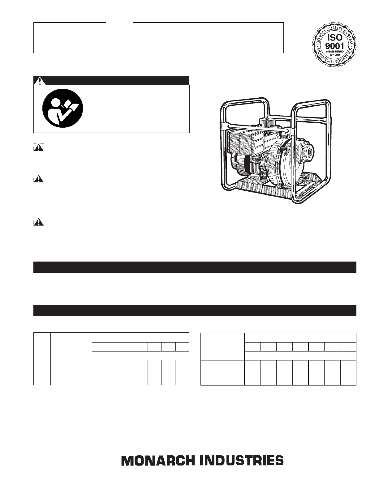
TSP SERIES
MANUAL
Self Priming Trash Pumps
PumpBiz.com
SAFETY WARNINGS
BEFORE OPERATING OR
INSTALLING THIS PUMP, READ
THIS MANUAL AND FOLLOW
ALL SAFETY RULES AND
OPERATING INSTRUCTIONS.
SAFETY
CAUTION
• DO NOT OPERATE THIS PUMP DRY!
• Review instructions before operating.
• Wear ear protection to reduce objectionable noise.
__________________________________________________
WARNING
• Turn off power before servicing.
• If fuel is spilled, avoid creating any source of ignition until the
fuel vapors have been cleaned up and removed.
CAREFULLY READ THESE SAFETY
MESSAGES IN THIS MANUAL AND
ON PUMP.
APPLICATION
This pump is suitable for installations where the vertical distance
from the pump to the water level does not exceed 25 ft. In off-set
PERFORMANCE
BASED ON 5’ SUCTION LIFT.
Total Head in Feet
Pump Pump Solids 30 40 50 60 70 80 90
Model Size Handling Capacity in U.S. Gallons per Minute
TSP 2 2” x 2” 1 1/8” 198 194 180 145 110 75 40
TSP 3 3” x 3” 1 1/2” 318 265 172 98 42
TSP 4 4” x 4” 2” 616 500 400 280 190 120 45
NOTE: This trash pump can handle pumping stones, leaves,
mud and other debris of sizes up to the listed solids handling for
the pump and up to 25% of the flow by volume.
installations, friction losses in the suction pipe must be taken into
consideration.
Total Head in Metres
Pump 9 12 15 18.5 21.5 23.5 27.5
Model Capacity in Litres per Minute
TSP 2 750 735 680 550 415 285 150
TSP 3 1205 1005 650 370 160
TSP 4 2330 1890 1515 1060 720 455 170
200162R3 0402
Page 2
INSTALLATION
(a) LOCATION: The pump should be installed in a dry and well
ventilated location which provides adequate drainage, room
for servicing and protection from freezing temperatures. The
pump should be placed on a firm and level foundation. It
should be blocked and anchored, or if possible bolted down
to prevent creeping due to vibration. Locating the pump as
close as possible to the source of liquid supply reduces the
friction losses in the suction pipie and provides maximum
capacities.
CAUTION
• Always ensure there is adequate ventilation to prevent
asphyxiation.
(b) SUCTION HOSE: Use clean non-collapsible hose of the
same diameter as the pump suction piping. Where long
lengths of suction hose are used, the suction pipe diameter
should be increased by one size. This will increase the priming time. Check hose connections for leaks and the hose
for cuts and cracks. Repair any leaks, cuts or cracks as
they reduce pump capacity. The suction pipe must always
slope upwards from the liquid source to the pumps to avoid
air pockets in the line. In cases where the pump needs to
be reprimed often and it is not necessary that maximum
capacities be obtained, it is advisable to use a 90° or 45°
elbow in the suction line. This enables the pump to prime
more quickly and also prevents bending of the hose. In
cases where a maximum flow is required over a prolonged
period of time, the suction line should be led almost horizontally to the pump. Non-toxic thread compound should
be used on all pipe joints and connections should be thoroughly tightened. A strainer should be connected to the
bottom end of the suction pipe and it should be well submerged at all times.
OPERATION - PRIMING THE PUMP
WARNING: DO NOT RUN THE PUMP BEFORE PRIMING IT, SINCE THE SEAL AND IMPELLER COULD BE
PERMANENTLY DAMAGED.
(a) ENGINE: Check the engine manufacturer’s owner’s manual
supplied with the pump for instructions on engine preparation and start-up procedures. Make sure oil is added to
engine crankcase before starting the unit.
(b) PRIMING (NON-PRESSURIZED SYSTEM): Never oper-
ate the pump dry as this may damage the pump seal. Remove the priming plug from the top of the pump casing. Fill
the pump casing with water through the priming plug. Replace the priming plug and start the engine. The pump
should prime in 1/2 to 2 1/2 minutes, depending on the suction hose. If an exceptionally long suction line is used, the
water in the casing may become overheated and vapor
locked. If this occurs, replace the water in the casing with
cold water, using the priming and drain plugs. Continue to
prime the pump.
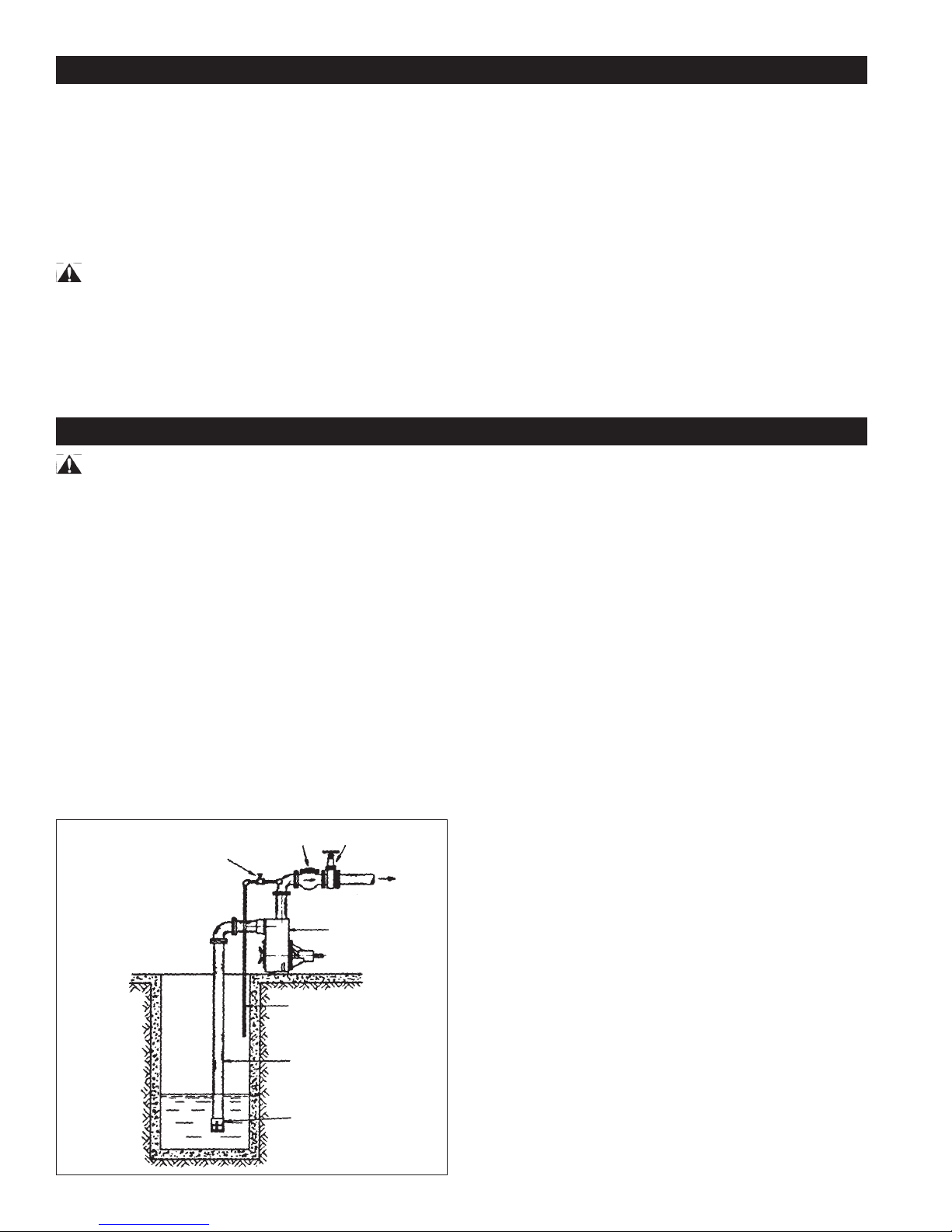
Figure 1
Gate Valve
(min. 3/4”)
Check Valve Gate Valve
Discharge
(c) PRIMING (PRESSURIZED SYSTEM): Place a check valve
on the discharge line of the pump. Place a pet cock or a ball
type air bleeder in place of the priming plug. Another alternative is to install an air bleed line with with gate valve onto
the discharge line, see Fig. 1. Open the priming port. Fill
the casing with water through the priming port. Replace the
plug or bleeder into the priming port. Open pet cock or ball
type air bleeder, and start engine. Once a continuous flow
of liquid emerges from the bleeder line, priming is complete
and the valve on pet cock can be closed off. The pump
should prime in 1/2 to 1 1 /2 minutes depending on suction
lift and the length and diameter of the suction hose. If an
exceptionally long suction line is used, the water in the casing may become overheated and vapor locked. If this occurs, replace the water in the casing with cold water using
the priming and drain plugs. Continue to prime the pump.
(d) UNCLOGGING: The pump is designed to enable the
impeller and volute to be unclogged without disconnecting
either suction or discharge hoses. Simply unbolt the four
large wing nuts and remove the front cover - suction hose
still attached. Remove the volute to expose the impeller.
All parts can then be readily cleaned.
Air Bleed Line
Suction Pipe
Strainer
Pump
(e) DRAINING: Should the pump be subject to freezing tem-
peratures, it will be necessary to drain the pump completely.
To drain, remove the drain plug located at the bottom of the
front casing and the priming plug and make sure that the
drain hold is not choked. After all of the water has been
drained out, operate the pump for a few seconds to ensure
that the impeller is devoid of water. Make sure that the suction line is also empty.
(f) STORAGE OF PUMP: Drain liquid from pump as explained
in the “Draining” section, to prevent freezing. It is recommended that a good rust inhibitor be put in the liquid end to
prevent excessive corrosion. Be sure motor is kept dry and
covered. When restoring the use of the pump, replace all
plugs and make sure all connections are tightly sealed. After a complete check, proceed with the initial prime according to the directions under the section “Priming”.
2
Page 3

MAINTENANCE
(a) LUBRICATION:
1) The pump requires no lubrication.
2) For gasoline or diesel engines, refer to the instructions
provided by the engine manuafacturer.
(b) REPLACING SEALS:
To disassemble:
1) Remove four nuts (8) and washers (23) and dismount
the front casing (1).
2) Remove the volute (7).
3) Inspect the seal (11) on the suction side of the volute.
It should be replaced if damaged.
4) Check ‘O’ Ring (10) in the groove of the front casing
(1). It should be replaced if damaged.
5) Unscrew the impeller (2) in a counter-clockwise direction.
6) Slip the rotating seal (12) with the sleeve (13) off of the
engine shaft.
7) Inspect the ceramic seat (12A) fixed in the rear casing
(3). If it is worn or damaged, it should be replaced.
Unbolt the rear casing from the engine and push the
ceramic seat out of its housing in the rear casing from
the engine end. Care must be taken so that the shaft is
not damaged in the process.
To reassemble:
1) Clean all parts thoroughly before reassembly.
2) Oil the rubber cup on the ceramic seat (12A) and push
it into the rear casing groove using thumbs only. Make
sure that the smooth surface of the ceramic seat faces
outwards.
3) Assemble the rear casing (3) to the engine being very
careful so as not to damage the ceramic seat. Do not
forget the lock washers or washer seals when assembling the rear casing to the engine.
4) Slide the rotating seal (12) onto the sleeve and then
slide the sleeve onto the shaft.
5) Screw on the impeller (2).
6) Position the volute (7) into the rear casing so that it
seats properly into the location diameter of the rear
casing. The volute is prevented from rotation by its
anti-rotation rib which seats into the slot on the side of
the rear casing. It may be necessary to tip the pump
rearwards to keep the volute in position until the front
casing is in position.
7) Slide the seal (11) on the shoulder of the volute.
8) Place the ‘O’ Ring into the groove of the front casing.
9) Assemble the front casing with the rear casing.
CAUTION
• Whenever the pump is dismantled and then reassembled,
always check to see that the impeller rotates freely within the
volute.
• All models have a flinger on the shaft (14). This flinger must
not be removed.
TROUBLESHOOTING CHART
PROBLEM CAUSE
• No discharge 1) Pump not properly primed.
• Reduced capacity and/or head 1) Air leaks in suction line.
• Pump loses prime 1) Air leaks in suction line.
• Excessive power consumption 1) Speed too high.
2) Speed to low.
3) Suction lift greater than that for which the pump was designed.
4) Discharge too high.
5) Collapsed or plugged suction hose.
2) Clogged impeller.
3) Strainer or foot valve not properly submerged.
4) Excessively worn impeller.
5) Speed too low.
6) Suction lift too great or insufficient NPSH. NPSH, Net Positive
Suction Head is the total suction head in feet of liquid (absolute) less
the vapor pressure of the liquid in feet (absolute).
7) Partially collapsed or plugged suction line.
2) Excessive amount of air or gas in liquid.
3) Loose seal (11) due to shrinkage or damage.
4) Suction pipe insufficiently submerged.
5) Suction lift too great.
6) Check if valve may be worn or have dirt lodged between the rubber
flap and the valve seat. This prevents the valve from retaining a
sufficient amount of water in the casing for proper priming.
2) Specific gravity or viscosity of liquid too high.
• Noise 1) Suction and discharge piping not properly supported and anchored.
2) Cavitation - check NPSH.
3
Page 4

PumpBiz.com
1-800-PUMPBIZ
LIMITED MONARCH INDUSTRIES WARRANTY
For one year from date of purchase, Monarch Industries will replace or repair for the original purchaser, free of
charge, any part or parts, found upon examination by any Monarch Industries Authorized Service Depot or by the
Monarch factory, to be defective in material or workmanship or both. Equipment and accessories not manufactured by Monarch Industries are warranted only to the extent of the original manufacturer's warranty. All transportation charges on parts submitted for replacement or repair under this warranty must be borne by the purchaser.
For warranty service see your nearest Monarch Industries Authorized Service Depot. THERE IS NO OTHER
EXPRESS WARRANTY. IMPLIED WARRANTIES INCLUDING THOSE OF MERCHANTABILITY AND
FITNESS FOR A PARTICULAR PURPOSE ARE LIMITED TO ONE YEAR FROM PURCHASE AND TO
THE EXTENT PERMITTED BY LAW. LIABILITY FOR CONSEQUENTIAL DAMAGES UNDER ANY AND
ALL WARRANTIES ARE EXCLUDED TO THE EXTENT EXCLUSION IS PERMITTED BY LAW.
This warranty is an addition to any statutory warranty.
Page 5

REPAIR PARTS LIST
LISTE DE PIÈCES DE
RECHANGE
LISTA DE PIEZAS DE
REPARACIONES
TSP SERIES
TSP 3, 3RF, 3H, 3HRF, 3D, TSP-3ICRF
Self-Priming Trash Pumps
Pompes pour eaux chargées à
amorçage automatique
Ref # Code # TSP-3 TSP-3RF TSP-3D TSP-3H TSP-3HRF Description
C C C D C Current Type D'usage courant
1 465032 1 1 1 1 1 Front Casing Boîtier de devant
2 465002 1 1 1 1 1 Impeller Roue de turbine
3
465022 N/A N/A N/A N/A N/A Rear Casing type A (see note a) Boîtier a l'arriere type A (siège nota a)
465017 1 1 1 1 1 Rear Casing type B Boîtier a l'arriere type B
465093 1 1 1 1 1 Rear Casing type C & D Boîtier a l'arriere type C & D
4 465042 1 1 1 1 1 Check Valve Cover Couvercle de soupape de retenue
5* 438486 1 1 1 1 1 Top Weight Poids Superieur
6* 135159 2 2 2 2 2 Pin 1/4 dia. x 1 SST type A & B Goupille dia.1/4 x 1 SST type A & B
172980 2 2 2 2 2 Stud 3/8 UNC x 1-1/2 SST Type C&D Bouton 3/8 UNC x 1-1/2 SST type C & D
7
465012 N/A N/A N/A N/A N/A Volute type A (see note a) Volute type A (siège nota a)
465014 1 1 1 1 1 Volute type B Volute type B
200229R5 0505
Ph: (204) 786-7921
Fax: (204) 889-9120
E-mail: orders@monarchindustries.com (english)
commandes@monarchindustries.com (french)
Page 6

Ref # Code # TSP-3 TSP-3RF TSP-3D TSP-3H TSP-3HRF Description
7 465005 1 1 1 1 1 Volute type C & D Volute type C & D
8* 456053 4 4 Buttery Nut-Special Ecrou oreille-Speciale
465046 4 4 4 Buttery Nut-Special Ecrou a orille-speciale
9* 190716 1 1 1 1 1 Rubber Flapper Clapet en Caoutchouc
10* 197989 1 1 1 1 1 O-ring #454 D70 Joint Torique #454 D70
11* 199696 1 1 1 1 1 Seal Joint
12* 240395 1 1 1 1 1 Mechanical Seal MS-95 Joint mecanique MS-95
13* 400136 1 1 1 1 1 Sleeve Manchon
14* 190848 1 Flinger Cavaler
191270 1 1 1 1 Flinger Cavalier
15 185650 2 2 2 2 2 Pipe Plug 3/4 NPT Bouchon à tuyau 3/4 NPT
16 176500 2 2 2 2 2 Lock Washer 3/8 SST type C & D Rondelle à blocage 3/8 SST type C & D
17* 128630 2 2 2 2 2 Nut 3/8 UNC Brass type C & D Ecrou 3/8 UNC type C & D
21* 164630 4 4 4 4 4 Stud 3/8 UNC x 1-1/2 Bouton 3/8 UNC x 1-1/2
22 128230 4 4 4 4 4 Nut 3/8 UNC grade 5 Ecrou 3/8 UNC grade 5
23 176688 4 4 4 4 4 Spring Lock Washer Int. 3/8 I.D. Rondelled à ressort 3/8 D.I.
28 120000 4 4 4 4 4 Bolt 3/8 UNC x 7/8 Boulon 3/8 UNC x 7/8
29 176530 10 4 2 10 4 Spring Lock Washer Int.5/16 I.D. Rondelle de ressort 5/16 D.I.
30 225970 1 1 1 1 1 Bolt 5/16 UNC x 7/8 Zn. pl Boulon 5/16 UNC x 7/8 Zn pl
31 128220 10 4 2 10 4 Nut 5/16 UNC Ecrou 5/16 UNC
32 174440 10 4 2 10 4 Washer 3/8 I.D. Rondelle 3/8 I.D.
33 119810 4 4 Bolt 5/16 UNC x 1-3/4 Boulon 5/16 UNC x 1-3/4
119820 4 4 Bolt 5/16 UNC x 2 Boulon 5/16 UNC x 2
34 119760 6 2 6 Bolt 5/16 UNC x 3/4 Boulon 5/16 UNC x 3/4
35* 165230 4 4 4 4 4 Stud 1/2 UNC x 1-1/2 Bouton 1/2 UNC x 1-1/2
36 465059 1 1 L.H. Channnel Voie Main Gauche
415451 1 L.H. Channel Voie Main Gauche
37 465058 1 1 R.H. Channel Voie Main Droite
415452 1 R.H. Channel Voie Main Droite
38 465062 1 1 Pump End Support Plate Plaque de support l'extremite de pompe
465048 1 Pump End Support Plate Plaque de support l'extremite de pompe
39 465060 1 1 Engine Support Plate Plaque de support du moteur
465047 1 Engine Support Plate Plaque de support du moteur
40 176010 4 4 Rubber Isolator Rondelle en Caoutchouc
41 227820 1 1 1 1 1 Nut 5/16 UNC Zn. pl. Ecrou 5/16 UNC Zn. pl.
42 175530 1 1 1 1 1 Washer 21/64 I.D. Rondelle 21/64 I.D.
50 201919 1 Engine 8HP B/S I/C Moteur 195432 Briggs & Stratton
201929 1 Engine 8HP B/S I/C Moteur Briggs & Stratton
202050 1 Engine Lombardini (see note b) Moteur Lombardini (siège nota b)
202002 1 1 Engine 8HP Honda Moteur 8CV Honda
51 176690 4 4 4 4 4 Tooth Lock Washer Int. 1/2 I.D. Rondelle à blocage dentee Int. 1/2 I.D.
80 128230 4 Nut 3/8 UNC grade 5 Ecrou 3/8 UNC grade 5
81 176540 4 Spring Lock Washer 3/8 I.D. Rondelle à ressort de blocage 3/8 I.D.
82 128250 4 Nut 1/2 UNC grade 5 Ecrou 1/2 UNC grade 5
83 176560 4 Spring Lock Washer 1/2 I.D. Rondelle à ressort de blocage 1/2 I.D.
84 174450 4 Washer 7/16 I.D. Rondelle 7/16 I.D.
85 120000 4 Bolt 3/8 UNC x 7/8 Boulon 3/8 UNC x 7/8
86 174470 4 Washer 7/16 I.D. Rondelle 7/16 I.D.
87 120430 4 Bolt 1/2 UNC x 1 Boulon 1/2 UNC x 1
99 465086 1 1 Roll Frame Weldment Bati envveloppant stablle
N/S 456065 1 Handle Poignée
N/S 433184 1 Handle Poignée
N/S 465090 1 1 1 1 1 Strainer Crepine
*Suggested parts to stock.
When ordering parts specify Model #, Code #, and Type.
(N/S not shown), (N/A not available).
IMPORTANT: Rear casing and Volute must be of the same Type.
NOTE: a) To replace Type A Volute or Rear casing, order Type C
items; 3,6,7,16 & 17.
b) No longer has decompression feature.
*Pièces suggerees pour stocker.
Lorsque vous commandez des pièces specier numero de modele et de code ainsi que le
type.
(N/S pas montre) (N/A refuse à toute).
Important: Boîtier à l'arriere et la volute doivent etre du meme type.
NOTE: a) Pour replacer une Volute ou une Boiter á l'arriere (type A),
commande type C numero 3, 6, 7, 16 & 17.
b) Pluo disponsible marquer decompression.
Ph: (204) 786-7921
Fax: (204) 889-9120
E-mail: orders@monarchindustries.com (english)
commandes@monarchindustries.com (french)
 Loading...