

Page 1
Page 2

Contents
Chapter 1 Overview ............................................................................................... 4
Chapter 2 Product Information .............................................................................. 6
2.1 Designation Rules ............................................................................................................6
2.2 Mounting Dimensions .......................................................................................................6
2.3 Electrical Specifications ....................................................................................................8
2.4 Braking Resistor .............................................................................................................11
2.5 Terminal Descriptions .....................................................................................................12
Chapter 3 Component Description ...................................................................... 16
3.1 Onboard Keypad Description .........................................................................................16
3.2 Use of the LED Operation Panel ....................................................................................18
3.3 CTB Board ......................................................................................................................20
3.4 Display Board (MCTC-HCB)...........................................................................................22
3.5 CCB Board .....................................................................................................................29
Chapter 4 Use of the NICE3000 .......................................................................... 32
4.1 Wiring Diagrams Under Default Parameter Settings ......................................................32
4.2 Description of Shaft Signals ...........................................................................................33
4.3 Typical Commissioning ...................................................................................................35
Chapter 5 Function Code Table ........................................................................... 52
Chapter 6 System Application ............................................................................. 72
6.1 Parallel Mode and Group Mode......................................................................................72
6.2 Emergency Evacuation at Power Failure .......................................................................75
6.3 Opposite Door Control ....................................................................................................78
Chapter 7 Troubleshooting .................................................................................. 82
7.1 Description of Fault Levels .............................................................................................82
7.2 Fault Information and Troubleshooting ...........................................................................83
Page 3

Page 4

1
Overview
Page 5
Overview Brief NICE3000 Instruction Manual
- 4 -
Chapter 1 Overview
To facilitate the users who use the NICE3000 control system for the first time to understand
how to commission the control system as quickly as possible, this manual briefly describes
the specifications, wiring, common parameter setting, and common commissioning of the
NICE3000.
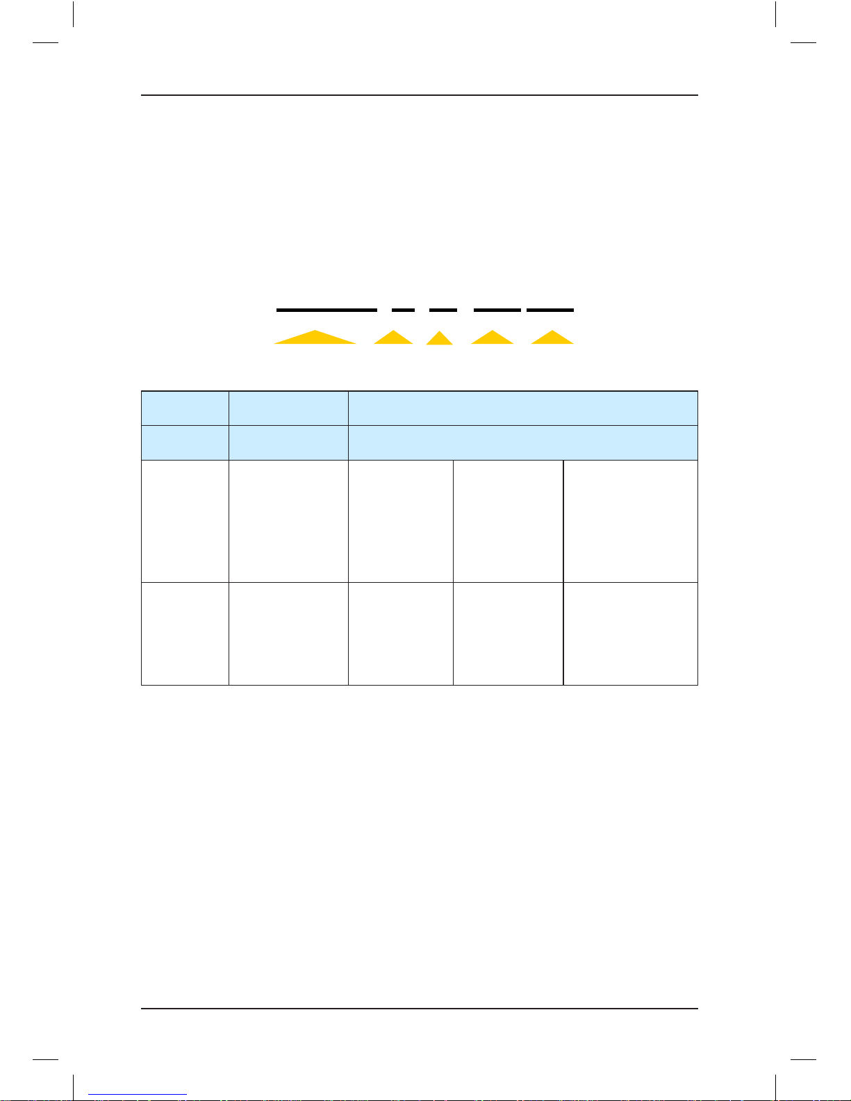
The application range of the NICE3000 is as follows:
Maximum Number
of Floors
Maximum Elevator
Speed
Parallel/Group Mode Inputs Outputs
40 4 m/s 2 to 8 elevators 24 6
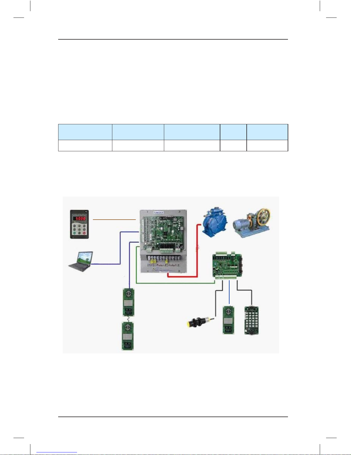
The NICE3000 series elevator integrated control system mainly includes the elevator
integrated controller, car top board (MCTC-CTB), hall call board (MCTC-HCB), car call
board (MCTC-CCB), and optional door pre-open module, and remote monitoring system.
The following figure shows the system architecture.
Figure 1-1 System architecture of the NICE3000
LED operation
panel
Host
computer
CAN bus
MCTC-HCB
MCTC-HCB
Load cell
MCTC-HCB
Modbus
MCTC-CCB
MCTC-CTB
PMSM or
asynchronous motor
Page 6

2
Product Information
Page 7
Product Information Brief NICE3000 Instruction Manual
- 6 -
Chapter 2 Product Information
2.1 Designation Rules
Figure 2-1 Designation rules of the NICE3000
NICE series
integrated controller
For lift
Controller
model
Three-phase
400 V
Motor power
NICE-L-A-40 11
Controller
Model
A B
Adaptable
Motor
Asynchronous
Motor
PMSM
Encoder
Incremental
encoder (pushpull output, opencollector output)
Incremental
encoder with
commutation
signals UVW
Incremental
SIN/COS
encoder with
sinusoidal
commutation
signals
Absolute SIN/
COS encoder
with EnDat serial
communications
protocol
(Heidenhain
ECN1313/413)
PG card
Main control
board (MCB)
integrating
the PG card,
requiring no
external one
MCTC-PG-B
MCTC-PG-D
MCTC-PG-C
MCTC-PG-E
MD32PG5
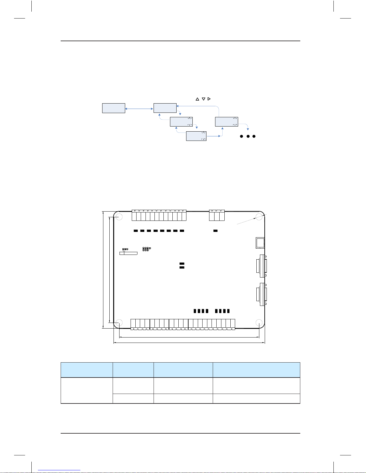
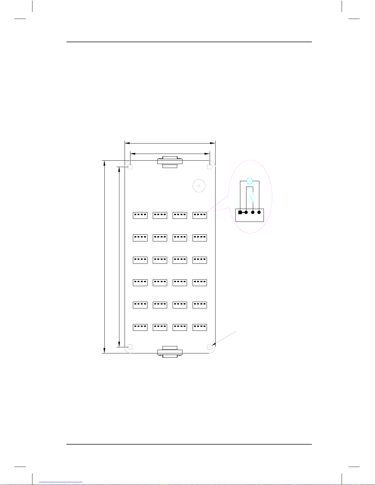
2.2 Mounting Dimensions
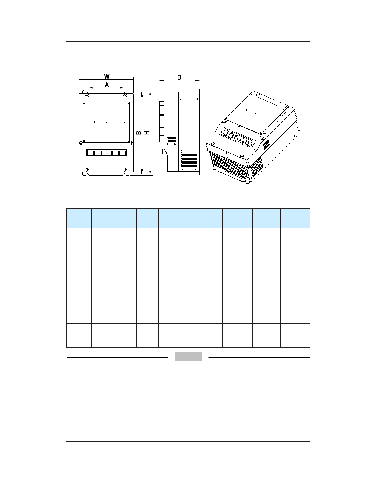
The NICE3000 controller has three sizes: SIZE-C, SIZE-D, and SIZE-E, as shown in the
following figure. SIZE-F is a customized model with different appearances but the same
installation mode.
The following figure and table show the appearance and physical dimensions of the
NICE3000 controller.
Page 8
Brief NICE3000 Instruction Manual Product Information
- 7 -
Figure 2-2 Appearance and mounting dimensions of the NICE3000 controller
Table 2-1 Sizes of the NICE3000 controller
Size Model
A
(mm)B (mm)H (mm)W (mm)D (mm)
Hole
Diameter
(mm)
Gross
Weight
(kg)
Structure
SIZE-C
P ≤ 5.5
kW
140 344 355 220 150 6.5 10 L
SIZE-D
5.5 kW
< P ≤
15 kW
150 334.5 347.5 223 167.5 6.5 12 L
5.5 kW
< P ≤
15 kW
190 305 322 208 212 6 6.5 L1
SIZE-E
15 kW
< P ≤
30 kW
235 541.5 554.5 289.6 223 6.5 14.5 L
SIZE-F
30 kW
< P ≤
45 kW
250 598 620
380
262 10 34 L
Note
1. The NICE3000 controller of other power ratings, such as above 45 kW is rarely applied in the
elevator, and therefore, specifications are not provided here. For future detail on the options and
availability, please contact Monarch.
2. SIZE-D has two types, sheet-metal (structure L) and plastic (structure L1), varying slightly in the
size.
Page 9
Product Information Brief NICE3000 Instruction Manual
- 8 -
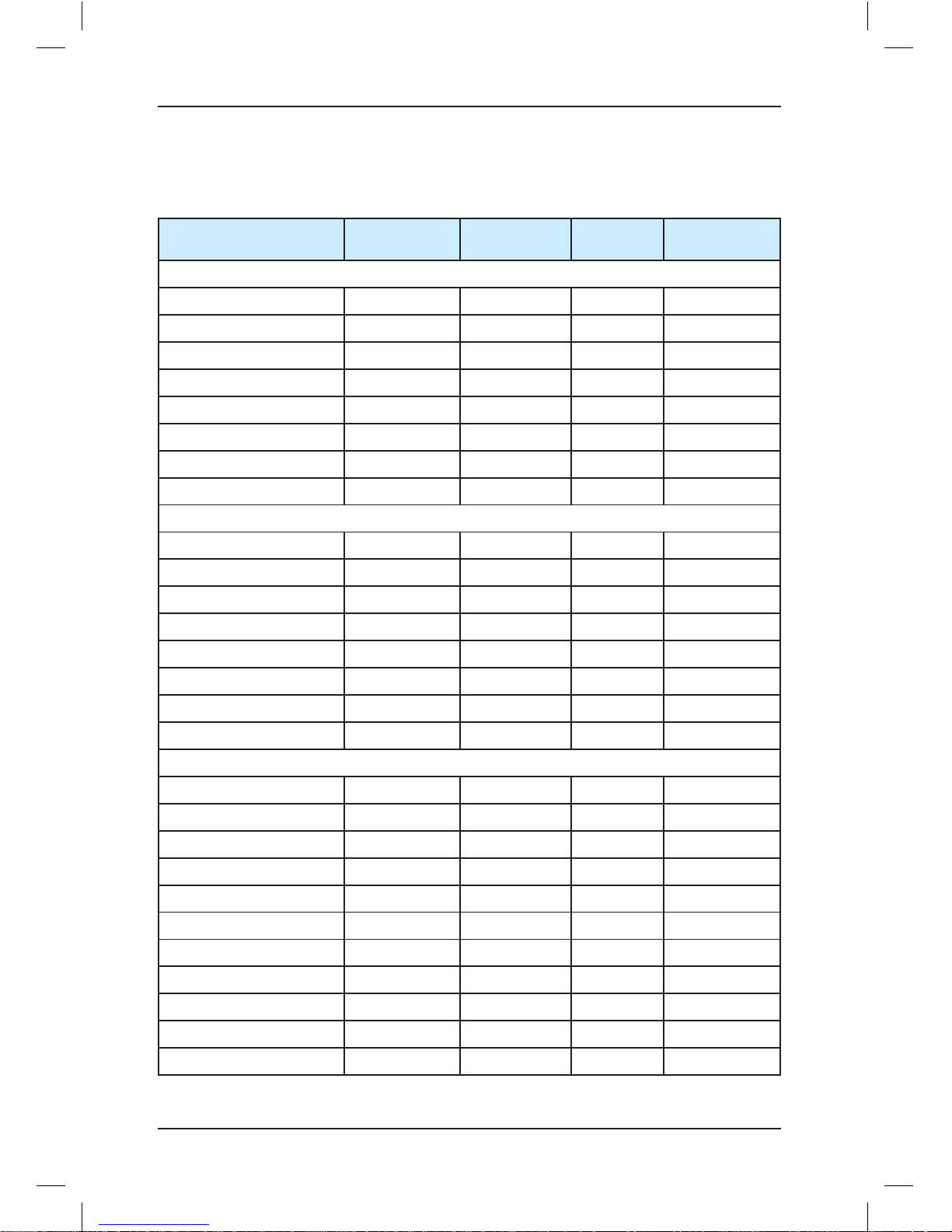
2.3 Electrical Specifications
Table 2-2 NICE3000 models and electrical specifications
System Model
Power
Capacity (kVA)
Input Current
(A)
Output
Current (A)
Motor Power
(kW)
AC supply voltage: single-phase 220 V, range: –15% to 20%
NICE-L-A/B-2002 2.3 13.2 5.2 1.1
NICE-L-A/B-2003 3.4 17 7.5 1.5
220-NICE-L/L1-A/B-4007 9.8 29 10.3 2.2
220-NICE-L/L1-A/B-4011 12.1 36 15.5 3.7
220-NICE-L/L1-A/B-4015 13.9 41 19 4.0
220-NICE-L-A/B-4018 17.3 40 22.5 5.5
220-NICE-L-A/B-4022 23.1 49 27.7 11
220-NICE-L-A/B-4030 33 61 34.6 15
AC supply voltage: three-phase 220 V, range: –15% to 20%
NICE-L-A/B-2002 4.0 11.0 9.6 2.2
NICE-L-A/B-2003 5.9 17.0 14.0 3.7
220-NICE-L/L1-A/B-4007 17.0 29.0 18.0 4.0
220-NICE-L/L1-A/B-4011 21.0 36.0 27.0 5.5
220-NICE-L/L1-A/B-4015 24.0 41.0 33.0 7.5
220-NICE-L-A/B-4018 30.0 40.0 39.0 11.0
220-NICE-L-A/B-4022 40.0 49.0 48.0 15.0
220-NICE-L-A/B-4030 57.0 61.0 60.0 18.5
AC supply voltage: three-phase 380 V, range: –15% to 20%
NICE-L-A/B-4002 4.0 6.5 5.1 2.2
NICE-L-A/B-4003 5.9 10.5 9.0 3.7
NICE-L-A/B-4005 8.9 14.8 13.0 5.5
NICE-L/L1-A/B-4007 11.0 20.5 18.0 7.5
NICE-L/L1-A/B-4011 17.0 29.0 27.0 11.0
NICE-L/L1-A/B-4015 21.0 36.0 33.0 15.0
NICE-L-A/B-4018 24.0 41.0 39.0 18.5
NICE-L-A/B-4022 30.0 49.5 48.0 22.0
NICE-L-A/B-4030 40.0 62.0 60.0 30.0
NICE-L-A/B-4037 57.0 77.0 75.0 37.0
NICE-L-A/B-4045 69.0 93.0 91.0 45.0
Page 10
Brief NICE3000 Instruction Manual Product Information
- 9 -
Note
1. In terms of single-phase and three-phase 220 VAC, NICE-L-A/B-2002 and NICE-L-A/B-2003
are specially designed for 220 VAC. The other models that are marked by prefixing "220-" are
modified from the three-phase 380 VAC models.
2. Same models are available for single-phase 220 VAC and three-phase 220 VAC. Pay attention
to the power rating of the adaptable motor during the use.
3. Select the proper controller output current based on the motor rated current. Ensure that the
controller output current is equal to or greater than the motor rated current.
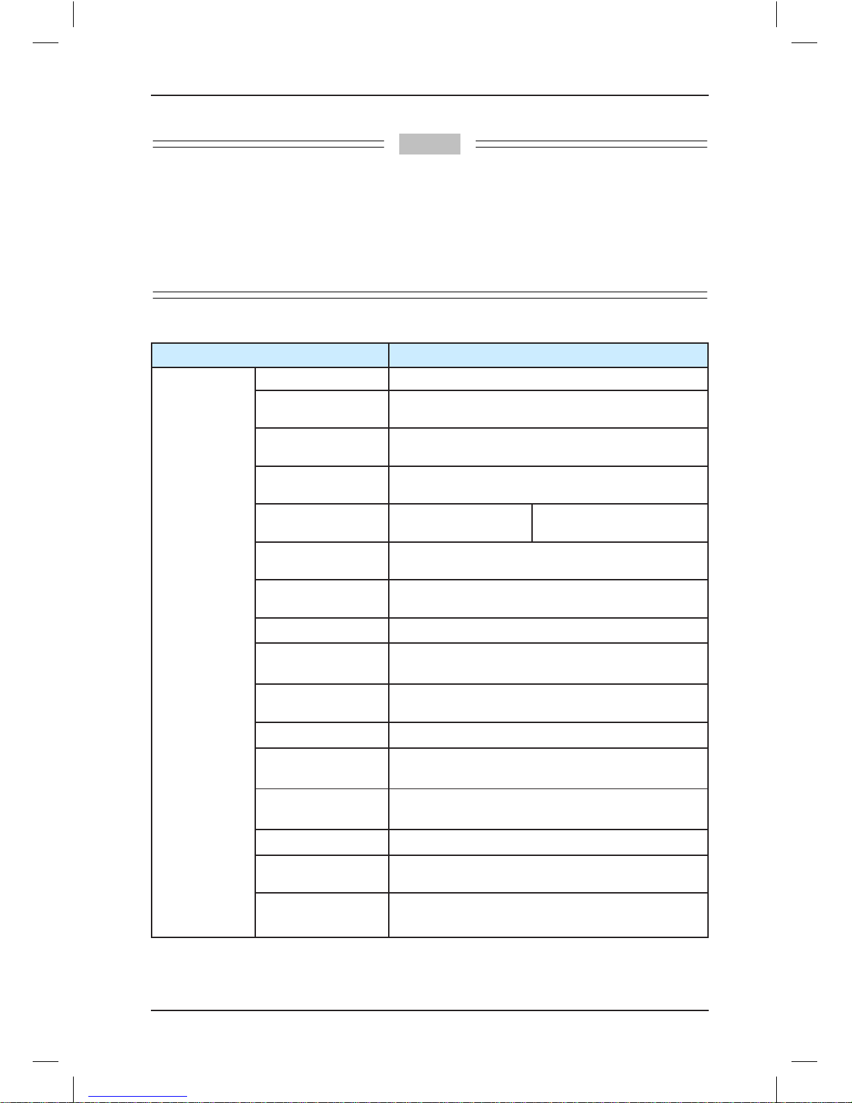
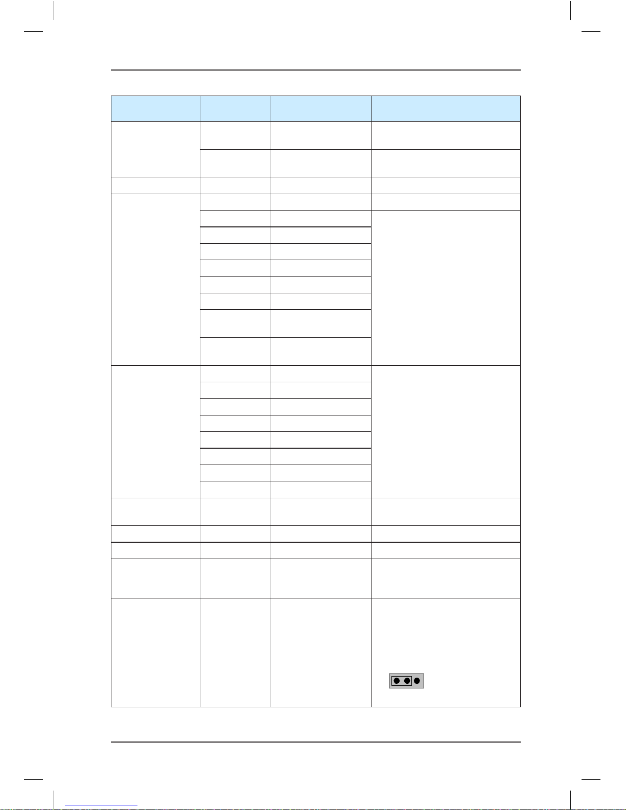
Table 2-3 Technical specifications of the NICE3000
Item Specification
Basic
specifications
Maximum frequency 99 Hz
Carrier frequency
0.5–16 kHz, adjusted automatically based on the
load features
Motor control mode
sensorless flux vector control (SFVC), closed-loop
vector control (CLVC)
Startup torque
0.5 Hz: 180% (SFVC)
0 Hz: 200% (CLVC)
Speed stability
accuracy
±0.5% (SFVC) ±0.05% (CLVC)
Torque control
accuracy
±5% (CLVC)
Overload
60s for 150% of the rated current, 1s for 200% of the
rated current
Motor auto-tuning With-load auto-tuning; no-load auto-tuning
Distance control
Direct flooring mode in which the leveling position
can be adjusted flexibly
Acceleration/
Deceleration curve
N curves generated automatically
Re-leveling Leveling re-adjustment after the car load changes
Slow-down
New reliable slow-down function, automatically
identifying the position of the slow-down shelf
Shaft auto-tuning
32-bit data, recording the position in the shaft
accurately
Leveling adjustment Flexible and easy leveling adjustment function
Startup torque
compensation
Humanized load cell auto-tuning
Real-time clock
Real-time clock for time-based floor service, peak
service and automatic password
Page 11
Product Information Brief NICE3000 Instruction Manual
- 10 -
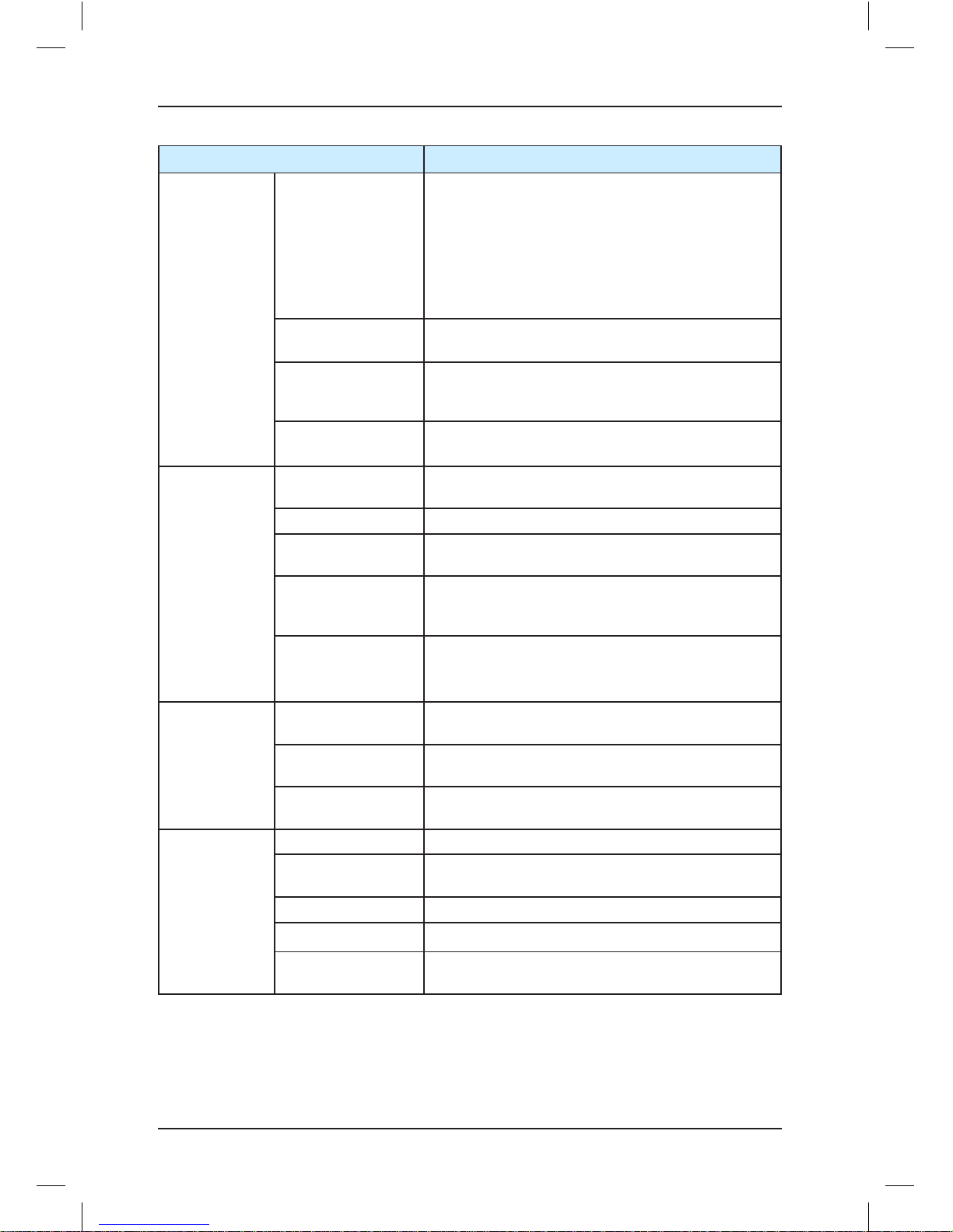
Item Specification
Basic
specifications
Fault protection
Providing 57 protections such as:
• Power-on short circuit detection
• Protection at power phase loss and output phase
loss
• Over-current protection
• Door machine fault protection
• Encoder protection
• Protection on multiple levels of elevator faults
Intelligent
management
Remote monitoring, user management, and group
control adjustment
Security check of
peripheral devices
after power-on
Security check of peripheral devices, such as
grounding and short circuit, after power-on
Status monitor
Monitoring the state of feedback signals to ensure
that the elevator works properly
I/O feature
Digital input (DI)
24 x DI
Input specification: 24 V, 5 mA
Analog input (AI) AI (voltage range: –10 V to +10 V)
Communication port
CTB communication (CANbus)
Hall call communication (Modbus)
Output terminal
block
6 x Relay output
The terminals can be allocated with different
functions.
Encoder interface
Incremental encoder (push-pull output and open
collector output) by standard
Different encoders via PG card
Operation and
display
Operation panel
5-digit LED display, displaying parameters such as
running speed and bus voltage
Keypad
3-digit LED display, implementing some
commissioning functions
Status monitor
Monitoring the state of the elevator, including CTB
and HCB
Environment
Altitude Below 1000 m
Ambient
temperature
–10°C to +40°C (derated if the ambient
temperature is between 40°C and 50°C)
Humidity Maximum relative humidity 95%, non-condensing
Vibration Maximum vibration: 5.9 m/s2 (0.6 g)
Storage
temperature
–20°C to +60°C
Page 12
Brief NICE3000 Instruction Manual Product Information
- 11 -
2.4 Braking Resistor
The models of 30 kW or below have a built-in braking unit, and you only need to connect an
external braking resistor between PB and + terminals. For models above 30 kW, you need
to install a braking unit and a braking resistor externally.
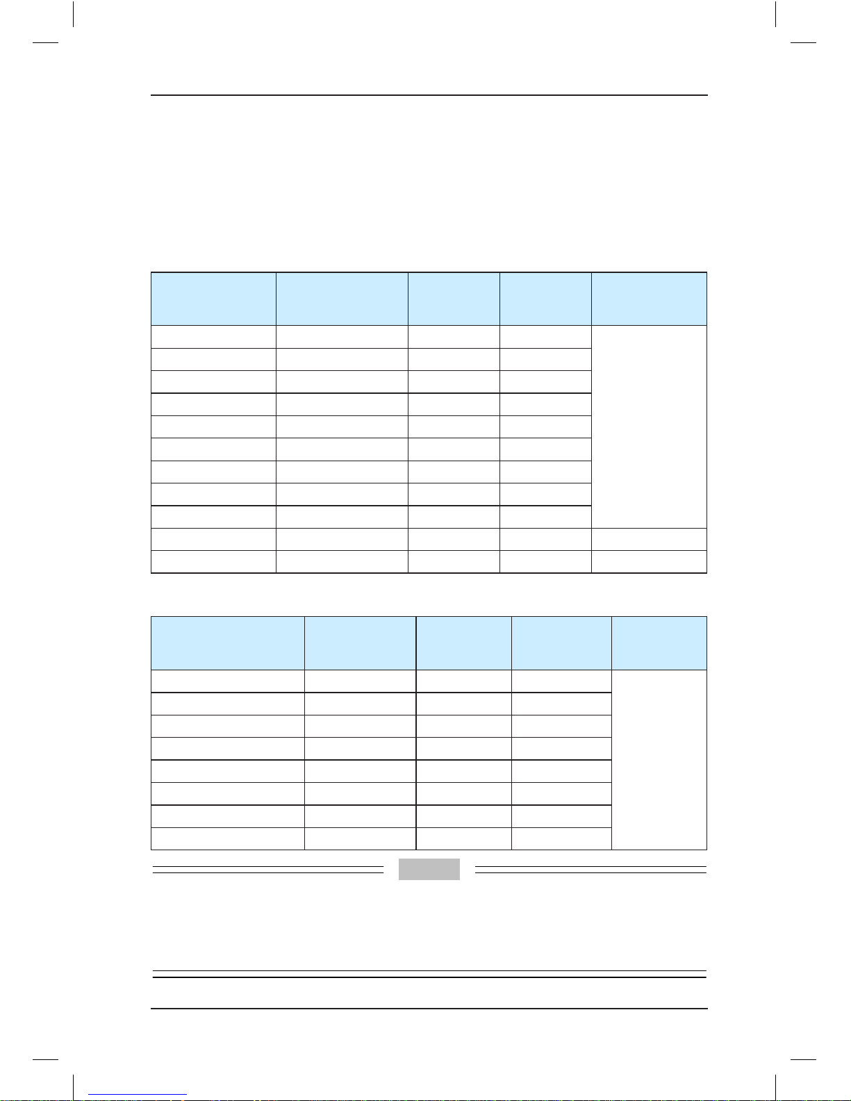
Select the braking resistor based on the configuration listed in the following table.
Table 2-4 Braking resistor selection for the three-phase 380 V controller
System Model
Average Power
of the Braking
Resistor (W)
Maximum
Resistance
(Ω)
Minimum
Resistance
(Ω)
Braking Unit
NICE-L-A/B-4002 650 230 150
Built-in by
standard
NICE-L-A/B-4003 1100 135 100
NICE-L-A/B-4005 1600 90 80
NICE-L-A/B-4007 2500 65 50
NICE-L-A/B-4011 3500 45 35
NICE-L-A/B-4015 4500 30 25
NICE-L-A/B-4018 5500 25 20
NICE-L-A/B-4022 6500 20 15
NICE-L-A/B-4030 9000 15 15
NICE-L-A/B-4037 11000 13 12 MDBUN-45-T
NICE-L-A/B -4045 13500 11 11 MDBUN-60-T
Table 2-5 Braking resistor selection for the 220 V controller
System Model
Average Power
of the Braking
Resistor (W)
Maximum
Resistance
(Ω)
Minimum
Resistance
(Ω)
Braking Unit
NICE-L-A/B-2002 650 70 55
Built-in by
standard
NICE-L-A/B-2003 1100 40 30
220-NICE-L-A/B-4007 2500 20 18
220-NICE-L-A/B-4011 3500 14 10
220-NICE-L-A/B-4015 4500 10 8
220-NICE-L-A/B-4018 5500 8 7
220-NICE-L-A/B-4022 6500 7 6
220-NICE-L-A/B -4030 9000 7 6
Note
1. The preceding configuration takes the synchronous motor as an example. The asynchronous
motor has poor energy transfer efficiency, and you can reduce the power of the braking resistor or
increase the resistance of the braking resistor.
2. It is recommended that you select the braking resistor closest to the maximum resistance.
Page 13
Product Information Brief NICE3000 Instruction Manual
- 12 -
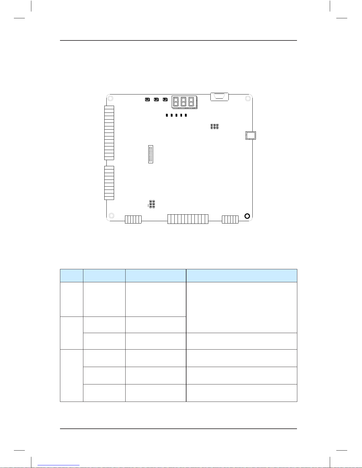
2.5 Terminal Descriptions
The following figure shows the structure of the MCB for the NICE3000.
Figure 2-3 Structure of the MCB
X1
X2
X3
X4
X5
X6
X7
X8
X9
X10
X11
X12
X13
X14
X15
X16
X17
X18
X19
X20
X21
X22
X23
X24
M
Ai
24V
COM
MOD+
MOD-
CAN+
CAN-
J9
RJ45
PRG UP SET
J10
Y1M1Y2M2Y3M3Y4M4Y5M5Y6
M6
CN7
CN3
CN9
CN1
ON
J6
CN5
CN12
J12
MCTC-MCB
J5
15V
PGM
PGA
PGB
PGM
PE
CN6
ER OK COP HOPMD BUS
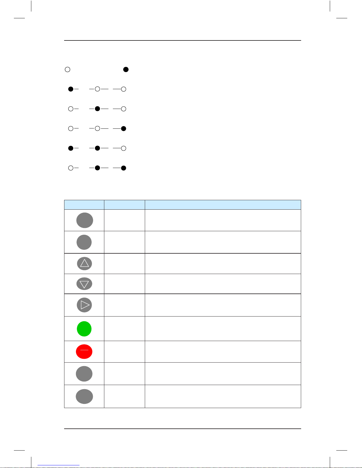
The NICE3000 provides a keypad with three keys and three 7-segment LEDs for display,
and five LED status indicators. The NICE3000 also supports the external LED operation
panel.
Table 2-6 Terminal description and specifications
Mark Code Terminal Name Function Description
CN1 X1 to X16 DI
Input voltage range: 10–30 VDC
Input impedance: 4.7 kΩ
Optocoupler isolation
Input current limit: 5 mA
Functions set in F5-01 to F5-24.
CN9
X17 to X24 DI
Ai/M AI Used for the analog load cell device
CN3
24V/COM
External 24 VDC
power supply
24 VDC power supply for the entire board
MOD+/-
RS485 differential
signal
Standard isolated RS485 communication
interface, used for hall call and display
CAN+/-
CANbus differential
signal
CANbus communication interface,
communication with the CTB
Page 14
Brief NICE3000 Instruction Manual Product Information
- 13 -
Mark Code Terminal Name Function Description
CN7
Y1/M1 to Y6/
M6
Relay output
Normally-open (NO), maximum current
and voltage rating: 5A, 250 VAC. The
functions are set in F5-26 to F5-31.
CN6
15V/PGM/
PGA/PGB/PE
Encoder interface for
asynchronous motor
Connecting the incremental encoder
(push-pull output or open collector output)
CN5 DB9 interface
RS232
communication
interface
Used as the interface for commission
software, cell monitoring, RS232/RS485
parallel control, and software download for
the MCB and drive board
CN12
RJ45
interface
Operation panel
interface
Used to connect the digital operation panel
J5
Used to connect the terminal resistor for the CANbus communication control board;
the pins marked with "ON" connected to the terminal resistor
J6
Used to connect the terminal resistor for the Modbus communication control board;
the pins marked with "ON" connected to the terminal resistor
J9/
J10
Software writing jumper block (used by the manufacturer). Do not short the pins
randomly; otherwise, the controller cannot be used properly
J12 Interface for connecting the PG card.
Table 2-7 Description of indicators on the MCB
Mark Terminal Name Function Description
ER Fault indicator
When a fault occurs, the system reports an alarm and this
indicator is on (red).
OK OK indicator When there is no fault, this indicator is on (green).
COP
CTB communication
indicator
When communication between the MCB and the CTB is
normal, this indicator is on (green).
HOP
HCB communication
indicator
When communication between the MCB and the HCB is
normal, this indicator is on (green).
MDBUS
Parallel/Group mode
indicator
This indicator is steady on (green) when the
communication for parallel mode or group mode is
normal, and blinks when the running in parallel mode or
group mode is normal.
X1 to X24 Input signal indicator ON when the 24 VDC input is active.
Y1 to Y6 Output signal indicator ON when the relay output is active.
Page 15

Page 16

3
Component Description
Page 17
Component Description Brief NICE3000 Instruction Manual
- 16 -
Chapter 3 Component Description
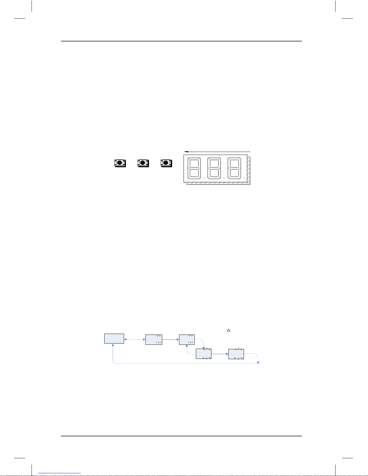
3.1 Onboard Keypad Description
The onboard keypad consists of three 7-segment LEDs and three buttons. You can query
information about the controller and enter simple commands on the keypad.
The following figure shows the appearance of the keypad.
Figure 3-1 Appearance of the keypad
PRG UP
SET
3 2 1
As shown in the preceding figure, the three buttons are PRG, UP, and SET. The functions of
the three buttons are as follows:
• PRG: Press this button in any state to display the current function group number.
You can press the UP button to change the function group number.
• UP: Press this button to increase the function group number.
Currently, the MCB defines a total of nine function code groups, namely, F0 to F8. You
can press the UP button to display them in turn. In addition, in special function code
group menu, you can input simple references by using the UP button.
• SET: In the function code group menu, press this button to enter the menu of the
function code group.
In special function code group menu, after you input a simple reference and press this
button to save the setting, the keypad enters the F0 menu by default.
The following figure shows the setting of increasing the called floor to 5.
05
F0
04
(Select the function
code group )
(Set the
parameter value )
Level-I menu
Level-II menu
PRG
Without
saving
SET
Saving
When there is a blinking
digit, press to modify it.
01
SET
Enter
Current floor
UP
Increase
(default display )
F1
PRG
Switch
UP
Increase
Page 18

Brief NICE3000 Instruction Manual Component Description
- 17 -
The function code groups displayed on the keypad are described as follows:
1. F0: display of floor and running direction
The F0 menu is displayed on the keypad by default upon power-on. The first 7-segment
LED indicates the running direction, while the last two 7-segment LEDs indicate the
current floor of the elevator.
When the elevator stops, the first 7-segment LED has no display. When the elevator
runs, the 1st 7-segment LED indicates the running direction.
When a system fault occurs, the 7-segment LEDs automatically display the fault code
and blink. If the fault is reset, the F0 menu is displayed.
2. F1: command input of the running floor
After you enter the F1 menu, the 7-segment LEDs display the bottom floor (F6-01). You
can press the UP key to set the destination floor within the range of lowest to top and
then press the SET key to save the setting. The elevator runs to the destination floor,
and the 7-segment LEDs automatically switch over to the F0 menu at the same time.
3. F2: fault reset
After you enter the F2 menu, the 7-segment LEDs display 0. When you press the UP
button to select 1 and press the SET button, the system fault is reset. After the system
fault is reset, the 7-segment LEDs automatically switch over to the F0 menu.
4. F3: time display
After you enter the F3 menu, the 7-segment LEDs display the current system time
circularly.
5. F4: contract number display
After you enter the F4 menu, the 7-segment LEDs display the user's contract number.
6. F5: running times display
After you enter the F5 menu, the 7-segment LEDs display the elevator running times
circularly.
7. F6: reserved
User setting is prohibited.
8. F7: shaft auto-tuning command input
After you enter the F7 menu, the 7-segment LEDs display 0. You can select 0 or 1 here,
where 1 indicates the shaft auto-tuning command available. After you select 1 and press
the SET button, shaft auto-tuning is implemented if the conditions are met. Meanwhile,
the 7-segment LEDs switch over to the F0 menu. After shaft auto-tuning is complete, F7
is back to 0 automatically. If shaft auto-tuning conditions are not met, fault code "E35" is
displayed.
9. F8: test function
After you enter the F8 menu, the 7-segment LEDs display 00. The setting range of F8 is
1–4, described as follows:
Page 19
Component Description Brief NICE3000 Instruction Manual
- 18 -
1: Hall call forbidden
2: Door open forbidden
3: Overload forbidden
4: Limit switches disabled
After the setting is complete, press SET. Then the 7-segment LEDs display E88 and
blink, prompting that the elevator is being tested. When you press PRG to exit, F8 is
back to 0 automatically.
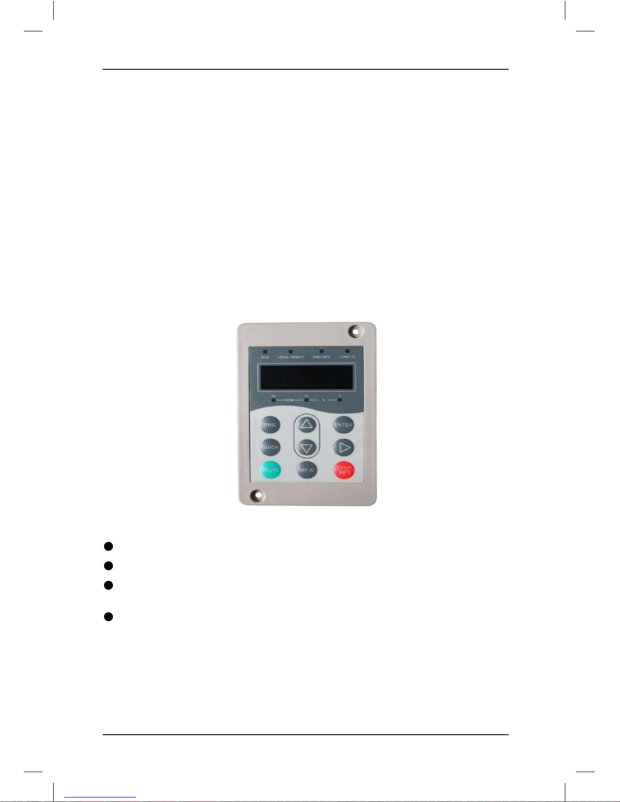
3.2 Use of the LED Operation Panel
The LED operation panel is connected to the RJ45 interface of the NICE3000 controller by
means of an 8-core flat cable. You can modify the function parameters, monitor the working
status, and run or stop the NICE3000 controller by using the LED operation panel. The
following figure shows the appearance of the LED operation panel.
Figure 3-2 Appearance of the LED operation panel
■ Function Indicators
RUN: This indicator is on when the NICE3000 is running.
LOCAL/REMOT: Reserved.
FWD/REV: It is the elevator direction indicator. ON indicates down direction, and OFF
indicates up direction.
TUNE/TC: It is the auto-tuning indicator. This indicator is on when the elevator is in auto-
tuning state.
Page 20
Brief NICE3000 Instruction Manual Component Description
- 19 -
■ Unit Indicators
indicates OFF, and indicates ON.
Hz A V
RPM %
Hz: unit of frequency
Hz A V
RPM %
A: unit of current
Hz A V
RPM %
V: unit of voltage
Hz A V
RPM %
RPM: unit of rotational speed
Hz A V
RPM %
%: percentage
■ Keys on the Operation Panel
Table 3-1 Keys on the operation panel
Key Name Function
PRG
Programming Enter or exit Level I menu.
ENTER
Confirm
Enter the menu interfaces level by level, and confirm the
parameter setting.
Increment Increase data or function code.
Decrement Decrease data or function code.
Shift
Select the displayed parameters in turn in the stop or running
state, and select the digit to be modified when modifying
parameters.
RUN
RUN
In operation panel control mode, press this key to run the
NICE3000.
STOP
RES
Stop/Reset
In operation panel control mode, press this key to stop the
running or reset the controller in fault state.
QUICK
Quick Enter or exit Level I shortcut menu.
MF.K
Fault display
Press this key to display or hide fault information in fault
state.
Page 21
Component Description Brief NICE3000 Instruction Manual
- 20 -
■ Operations on the Three-Level Menu
The following figure shows the operation procedure on the three-level menu.
Figure 3-3 Operation procedure on the three-level menu
F0
F0-06
50.00
(Select the functio n
code group)
(Select the
function code)
(Set the value o f
the function code)
Level-I menu
Level-II menu
Level-III menu
PRG
PRG
Not to save
the setting
ENTER
To save
the setting
ENTER
0.000
ENTER
Status parameter
PRG
F0-07
ENTER
PRG
Next function
code
(default di splay)
If there is a blinking digit , press
/ / to modify the digit .
3.3 CTB Board
The car top board (MCTC-CTB) is the elevator car control board of the NICE3000 controller.
It consists of eight DI terminals, one AI terminal, and nine relay output terminals. The CTB
can communicate with the CCB and HCB. The following figure shows the structure and size
of the CTB.
Figure 3-4 Structure and size of the CTB
J9
CAN
RESET
CN2 CN1 CN6 CN3
CN4 CN5
CN10
CN7
CN8
MCTC-
CTB
152 mm
162 mm
115 mm
125 mm
Φ
4
.
9
m
m
X1X2X3X4 X5X6X7X8
A1
B1
B2
B3
C2
C1
D2
D1
C3
24V
CAN+
CAN-
COM
24V
MOD+
MOD-
COM
24V
Ai
M
X1X2X3
X4
P24
P24
X5X6X7
X8
A
B
AM
CM
B3B2B1
BM
DM
C3
C3M
C2
C1
D2
D1
PARALLEL
ON
J2
Table 3-2 Description of CTB terminals
Type Terminal Name Description
CN2
(communication
with the MCB)
+24V/COM
External 24 V power
supply
24 VDC power supply to the
entire board
CAN+/CAN- CAN communication Connecting the MCB
Page 22
Brief NICE3000 Instruction Manual Component Description
- 21 -
Type Terminal Name Description
CN1
(communication
with the HCB)
+24V/COM 24 V power supply
24 VDC power supply to the
HCB
MOD+/MOD-
Modbus
communication
Communication with the HCB
CN6 (AI) Ai-M Load cell signal input 0–10 VDC
CN3 (DI)
P24 24 V power supply DI common terminal
X1 Light curtain 1
1. Photocoupler isolation,
unipolarity input
2. Input impedance: 3.3 kΩ
3. Positive logic
X2 Light curtain 2
X3 Door open limit 1
X4 Door open limit 2
X5 Door close limit 1
X6 Door close limit 2
X7
Full-load signal
(100%)
X8
Overload signal
(110%)
CN4 (relay
output)
B1-BM Door open signal 1
30 VDC, 1 A
B2-BM Door close signal 1
B3-BM Forced door close 1
C1-CM Door open signal 2
C2-CM Door close signal 2
C3-C3M Forced door close 2
D1-DM Up arrival signal
D2-DM Down arrival signal
CN5 A-AM
Car fan and lamp
control
250 VAC, 3 A; 30 VDC, 1 A
CN7/8 DB9 pin port CCB communication Connecting the CCB
CN10 RJ45 RJ45 Reserved
J9
Software
writing
interface
Software writing
interface
Used by the manufacturer
J2
ON/
PARALLEL
Address jumper
Setting the CTB addresses:
short PARALLEL for a single
elevator; short PARALLEL for
the master elevator and ON for
the slave elevator in parallel
mode.
J2
P ARA LLE LON
Page 23

Component Description Brief NICE3000 Instruction Manual
- 22 -
Type Terminal Name Description
CAN Indicator
Communication
indicator
This indicator blinks when the
CTB communicates with the
MCB.
RESET Indicator Fault indicator
This indicator blinks and the
CAN indicator is steady on
when a fault occurs during
communication between the
CTB and the MCB.
X1–X8 Indicator Input indicator
This indicator is on (green) when
the external input is active.
A–D Indicator Output indicator
This indicator is on (green) when
the system output is active.
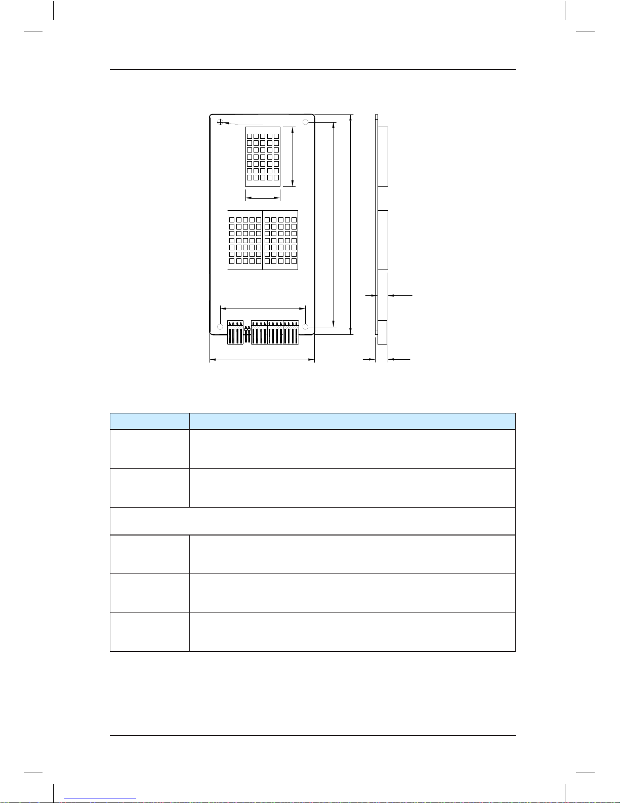
3.4 Display Board (MCTC-HCB)
As an important interface between users and the control system, the MCTC-HCB receives
hall calls and displays the current floor and running direction for the hall. This board can also
be used as car display board.
Monarch provides many types of display boards. The following describes only a few
common types. If you need other types, please contact Monarch.
The common types to be described are listed in the following table.
Table 3-3 Common types of HCB-H
Name Feature Size (mm)
HCB-H Dot-matrix display board (red) 144 x 70 x 18
HCB-R1 Ultrathin dot-matrix display board (red) 144 x 70 x 10
HCB-D2
Ultrathin segment LED display board (blue
background white display)
144 x 70 x 10
HCB-U1
4.3-inch segment LED display board (blue
background white display)
143.5 x 79.2 x 9.4
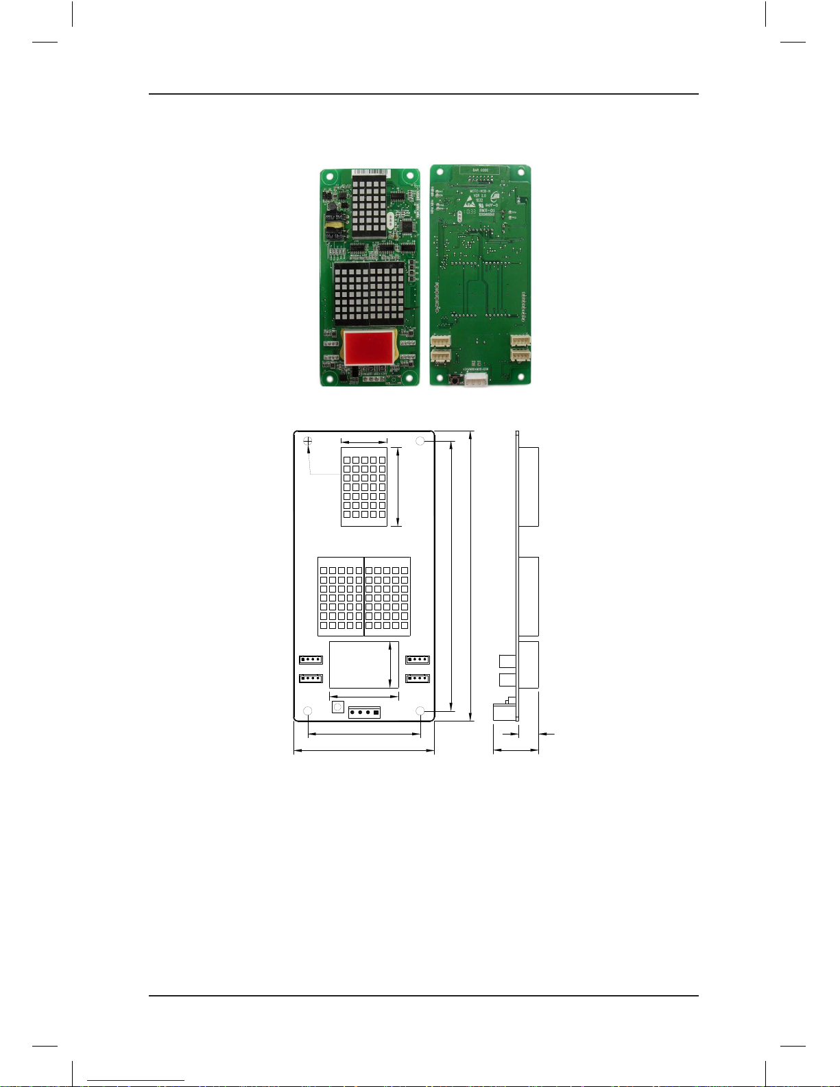
3.4.1 HCB-H (Dot-Matrix Display Board)
The following figures show the appearance and size of HCB-H.
Page 24
Brief NICE3000 Instruction Manual Component Description
- 23 -
Figure 3-5 Appearance of HCB-H
Figure 3-6 Size of HCB-H
4-Φ4.2 mm
56.0 mm
134.0 mm
70.0 mm
144.0 mm
9.9
mm
22.5 mm
22.9 mm
39.1 mm
34.3 mm
22.9 mm
S1
CN1
JP1 JP2
JP3 JP4
UP
DOWN
MCTC-HCB-H
Page 25

Component Description Brief NICE3000 Instruction Manual
- 24 -
The following table describes the input and output terminals.
Table 3-4 Input and output terminals of HCB-H
Terminal Name Function
JP1
Interface for the elevator locking switch and up arrival indicator
Pins 2 and 3 are for switch input. Pin 1 and 4 are power supply for the up
arrival indicator.
JP2
Interface for the fire-emergency switch and down arrival indicator
Pins 2 and 3 are for switch input. Pin 1 and 4 are power supply for the
down arrival indicator.
JP3
Interface for the up call button and indicator
Pins 2 and 3 are for up call input. Pins 1 and 4 are power supply for the up
call indicator.
JP4
Interface for the down call button and indicator
Pins 2 and 3 are for down call input. Pins 1 and 4 are power supply for the
down call indicator.
Note: Pins 1 and 2 are positive of power supply. The pin with white dot or that is rectangular
is pin 1.
S1
Button for setting the floor address.
Hold down the button to adjust the floor address. After you stop pressing,
the address number blinks three times, and therefore, the setting is
successful.
CN1
Modbus communication and power supply terminal
Pins 2 and 3 are for Modbus communication. Pins 1 and 4 are for DC
power supply.
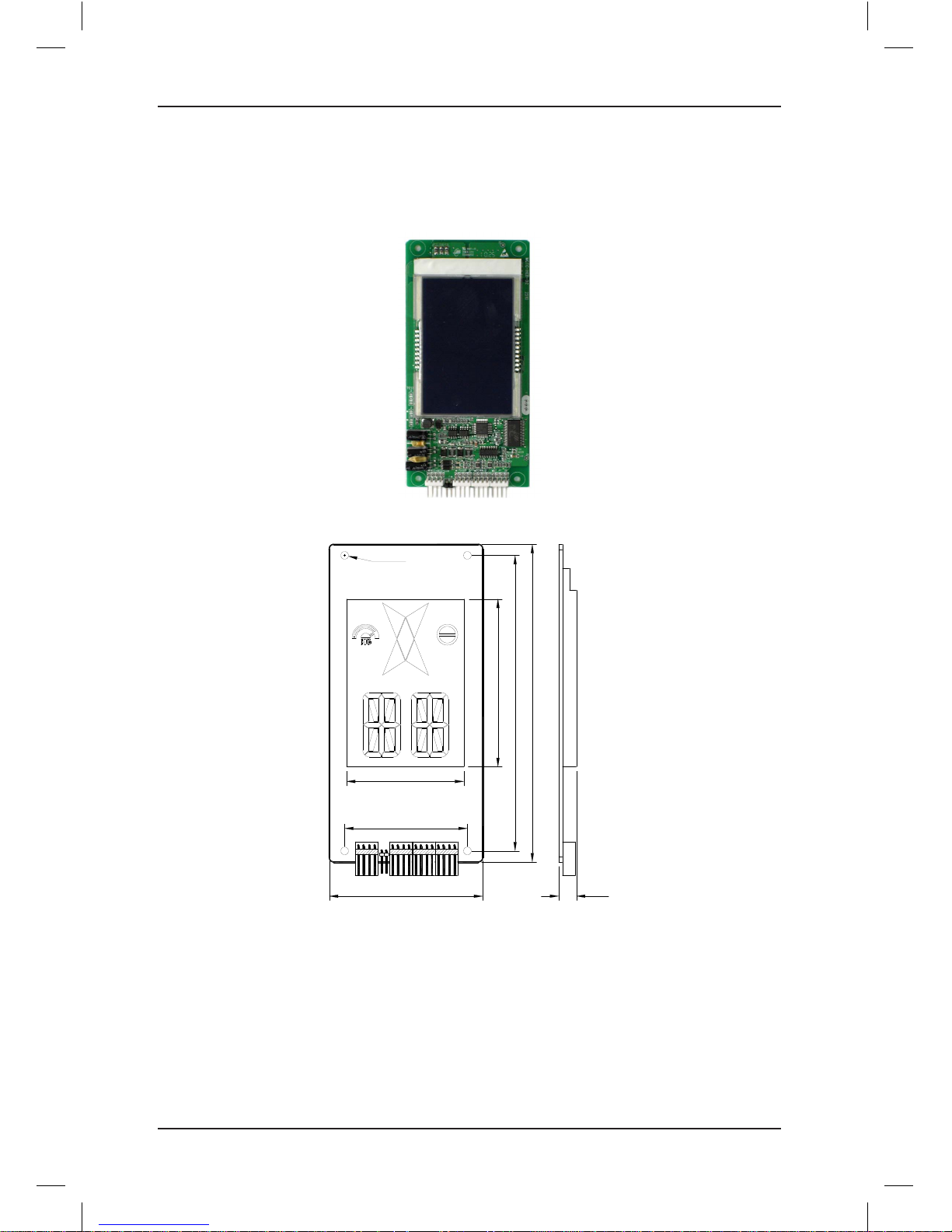
3.4.2 HCB-R1 (Ultrathin Dot-Matrix Display Board)
The following figures show the appearance and size of HCB-R1.
Figure 3-7 Appearance of HCB-R1
Page 26
Brief NICE3000 Instruction Manual Component Description
- 25 -
Figure 3-8 Size of HCB-R1
4-Φ3.5 mm
56.0 mm
134.0 m m
144.0 mm
6.7 mm
10 mm
22.8 mm
39.0 mm
CN1J1UP DOWN ST XF
70 mm
MCTC-HCB-R1
The following table describes the input and output terminals.
Table 3-5 Input and output terminals of HCB-R1
Terminal Name Function
UP
Interface for the up call button and indicator
Pins 2 and 3 are for up call input. Pins 1 and 4 are power supply for the up
call indicator.
DOWN
Interface for the down call button and indicator
Pins 2 and 3 are for down call input. Pins 1 and 4 are power supply for the
down call indicator.
Note: Pins 1 and 2 are positive of power supply. The pin with white dot mark or that is
rectangular is pin 1.
XF/ST
Interface for the fire-emergency and elevator locking switch
Pins 1 and 2 are for fire-emergency input. Pins 3 and 4 are for elevator
locking input.
J1
Terminal for setting the floor address.
Short J1, and press the UP button or DOWN button to set the floor address.
After the jumper cap is removed, the address is automatically stored.
CN1
Modbus communication and power supply terminal
Pins 2 and 3 are for Modbus communication. Pins 1 and 4 are for DC power
supply.
Page 27
Component Description Brief NICE3000 Instruction Manual
- 26 -
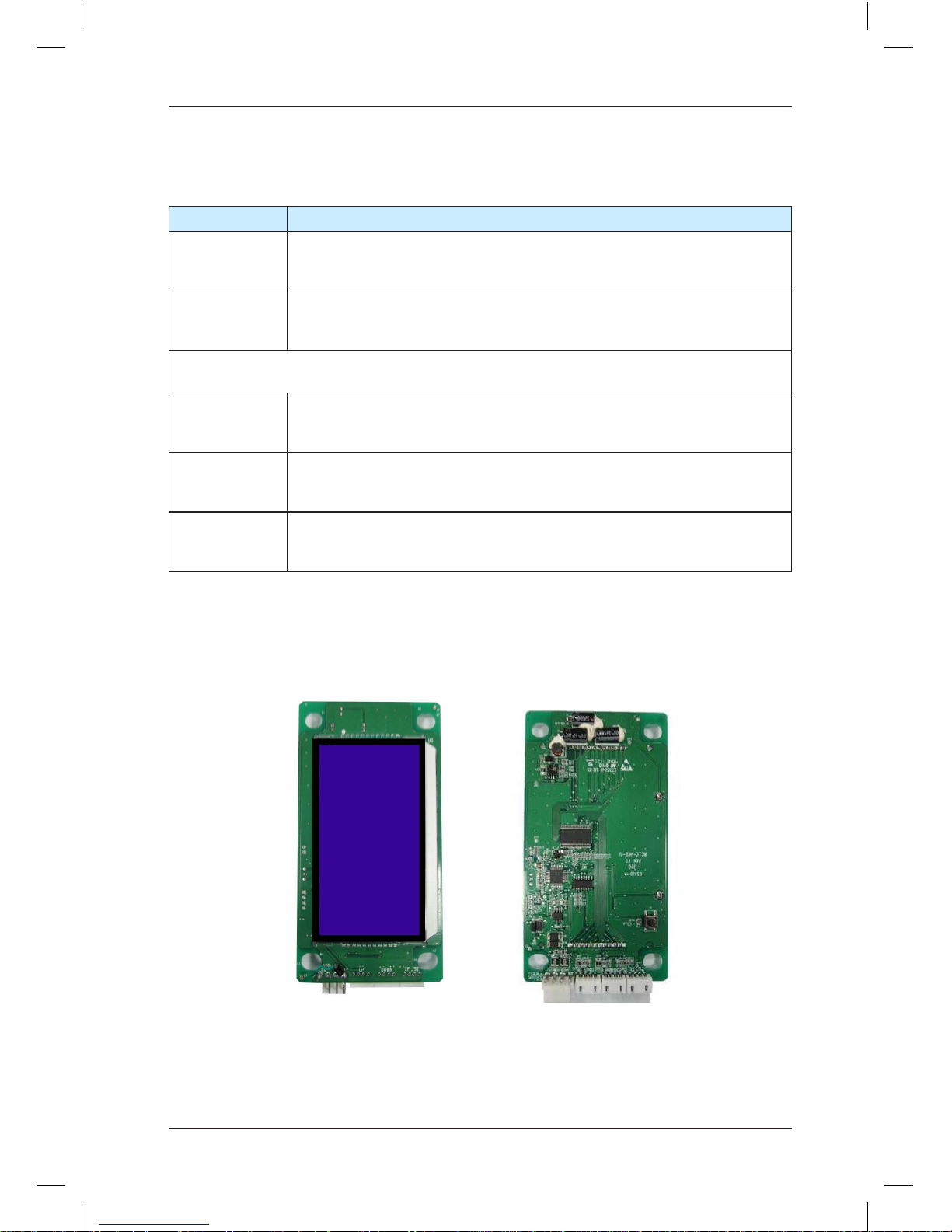
3.4.3 HCB-D2 (Ultrathin Segment LED Display Board)
The following figures show the appearance and size of HCB-D2.
Figure 3-9 Appearance of HCB-D2
Figure 3-10 Size of HCB-D2
4-Φ3.5 mm
56.0 mm
134.0 mm
70.0 mm
144.0 mm
10 mm
76.0 mm
49 mm
CN1J1UP DOWN ST XF
Page 28
Brief NICE3000 Instruction Manual Component Description
- 27 -
The following table describes the input and output terminals.
Table 3-6 Input and output terminals of HCB-D2
Terminal Name Function
JP2
Interface for the up call button and indicator
Pins 2 and 3 are for up call input. Pins 1 and 4 are power supply for the up
call indicator.
JP3
Interface for the down call button and indicator
Pins 2 and 3 are for down call input. Pins 1 and 4 are power supply for the
down call indicator.
Note: Pins 1 and 2 are positive of power supply. The pin with white dot mark or that is
rectangular is pin 1.
JP1
Interface for the fire-emergency and elevator locking switch
Pins 1 and 2 are for fire-emergency input, and pins 3 and 4 are for elevator
locking input.
J1
Terminal for setting the floor address.
Short J1, and press the UP button or DOWN button to set the floor address.
After the jumper cap is removed, the address is automatically stored.
CN1
Modbus communication and power supply terminal
Pins 2 and 3 are for Modbus communication. Pins 1 and 4 are for DC power
supply.
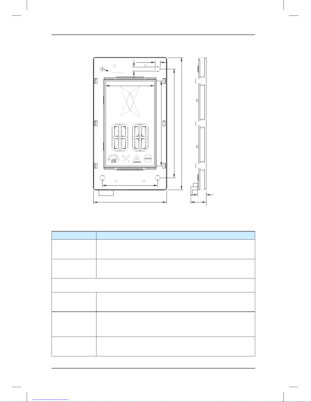
3.4.4 HCB-U1 (4.3-inch Segment LED Display Board)
The following figures show the appearance and size of HCB-U1.
Figure 3-11 Appearance of HCB-U1
Page 29
Component Description Brief NICE3000 Instruction Manual
- 28 -
Figure 3-12 Size of HCB-U1
3-5.5 mm
3-4.5 mm
9.4 mm
Φ4.5 mm
143.5 mm
79.2 mm
118.0 mm
60.0 mm
53.0 mm
92.0 mm
16.9 mm
The following table describes the input and output terminals.
Table 3-7 Input and output terminals of HCB-U1
Terminal Name Function
J1
Interface for the up call button and indicator
Pins 2 and 3 are for up call input. Pins 1 and 4 are power supply for the
up call indicator.
JP3
Interface for the down call button and indicator
Pins 2 and 3 are for down call input. Pins 1 and 4 are power supply for
the down call indicator.
Note: Pins 1 and 2 are positive of power supply. The pin with white dot mark or that is
rectangular is pin 1.
J3
Interface for the fire-emergency and elevator locking switch
Pins 1 and 2 are for fire-emergency input, and pins 3 and 4 are for
elevator locking input.
S1
Button for setting the floor address.
Hold down the button to adjust the floor address. After you stop pressing,
the address number blinks three times, and therefore the setting is
successful.
CN1
Modbus communication and power supply terminal
Pins 2 and 3 are for Modbus communication. Pins 1 and 4 are for DC
power supply.
Page 30
Brief NICE3000 Instruction Manual Component Description
- 29 -
3.5 CCB Board
The car call board (MCTC-CCB) is another interface between users and the control
system. Each CCB comprises 24 inputs and 22 outputs, including 16 floor buttons and 8
functional signals. The CCB mainly collects button calls and outputs signals of the button
call indicators. The need for 31-floor use can be implemented through cascaded connection.
CN2 is an input connector and CN1 is a cascaded output connector.
The following figure shows the structure of the CCB.
Figure 3-13 Structure of the CCB
1 2 3 4 1 2 3 4 1 2 3 4 1 2 3 4
1 2 3 4 1 2 3 4 1 2 3 4 1 2 3 4
1 2 3 4 1 2 3 4 1 2 3 4 1 2 3 4
1 2 3 4 1 2 3 4 1 2 3 4 1 2 3 4
1 2 3 4 1 2 3 4 1 2 3 4 1 2 3 4
1 2 3 4 1 2 3 4 1 2 3 4 1 2 3 4
JP1 JP2 JP3 JP4
JP5 JP6 JP7 JP8
JP9 JP10 JP11 JP12
JP13 JP14 JP15 JP16
JP17 JP18 JP19 JP20
JP21 JP22 JP23 JP24
CN1
Buzzer
Floor 1 Floor 2 Floor 3 Floor 4
Floor 5 Floor 6 Floor 7 Floor 8
Floor 9 Floor 10 Floor 11 Floor 12
Floor 13 Floor 14 Floor 15 Floor 16
Attendant
Direction
change
Independent
running
Fire
emergency
Door
open
Door
close
Door open
delay
Bypass
1 2 3 4
79 mm
69 mm
158 mm
148 mm
R
2
.
5
m
m
Output of the
button call
indicators
Button call
input
MCTC-CCB
CN2
Page 31

Component Description Brief NICE3000 Instruction Manual
- 30 -
The following table describes the input and output terminals.
Table 3-8 Input and output terminals of the CCB
No. Interface Pins 2 and 3 Pins 1 and 4 Remarks
1 JP1 Floor 1 button input Floor 1 display output
For CCB2, the
input signal of JPn
corresponds to floor
(16+n) button input.
2 JP2 Floor 2 button input Floor 2 display output
3 JP3 Floor 3 button input Floor 3 display output
4 JP4 Floor 4 button input Floor 4 display output
5 JP5 Floor 5 button input Floor 5 display output
6 JP6 Floor 6 button input Floor 6 display output
7 JP7 Floor 7 button input Floor 7 display output
8 JP8 Floor 8 button input Floor 8 display output
9 JP9 Floor 9 button input Floor 9 display output
10 JP10 Floor 10 button input Floor 10 display output
11 JP11 Floor 11 button input Floor 11 display output
12 JP12 Floor 12 button input Floor 12 display output
13 JP13 Floor 13 button input Floor 13 display output
14 JP14 Floor 14 button input Floor 14 display output
15 JP15 Floor 15 button input Floor 15 display output
16 JP16 Floor 16 button input Floor 16 display output
17 JP17
Door open button
input
Door open display
output
Invalid for CCB 2.
18 JP18
Door close button
input
Door close display
output
19 JP19
Door open delay
button input
Door open delay display
output
20 JP20 Bypass input Bypass display output
21 JP21 Attendant input Reserved
22 JP22
Direction change
input
Reserved
23 JP23
Independent running
input
Reserved
24 JP24 Firefighter input Reserved
Note: Pins 1 and 2 are positive of power supply. The pin with white dot mark or that is
rectangular is pin 1.
Page 32

4
Use of the NICE3000
Page 33

Use of the NICE3000 Brief NICE3000 Instruction Manual
- 32 -
Chapter 4 Use of the NICE3000
4.1 Wiring Diagrams Under Default Parameter Settings
4.1.1 Electric Wiring of the NICE3000
The following figure shows the electric wiring diagram of the NICE3000.
Figure 4-1 Electric wiring diagram of the NICE3000
X1
X2
X3
X4
X5
X6
X7
X8
X9
X10
X11
X12
X13
X14
X15
X16
X17
X18
X19
X20
X21
X22
X23
X24
M
Ai
R T+
-
U V W
PE
2 4V
COM
MOD+
M OD-
C AN+
C AN-
PG card
J9
PB
Up slow-down 1
Down leveling
Down slow-down 1
RUN contactor feedback
Safety circuit feedback
Door lock circuit feedback
S
Brake contactor feedback
RJ45
Encoder
Inspection
circuit
Analog weighing
Connect
to HCB
Connect
to CTB
PRG UP SET
Up leveling
Inspection signal
Up limit
Inspection up
Inspection down
Down limit
J10
Y1M1Y2M2Y3M3Y4M4Y5M5Y6
M6
CN7
CN3
CN9
CN1
ON
J5
24V
CN2
CN12
PE
24V
power
RUN output
Brake output
Encoder interface for
asynchronous motor
J6
15V
PGM
PGA
PGB
PGM
PE
CN6
Up slow-down 2
Up slow-down 3
Down slow-down 3
Down slow-down 2
1.5 m/s < elevator speed ≤ 2.4 m/s
2.4 m/s < elevator speed
Page 34

Brief NICE3000 Instruction Manual Use of the NICE3000
- 33 -
Note
The above wiring diagram shows the default I/O function setting of group F5. The braking resistor
is connected to PB and +.
4.1.2 Recommended CTB Wiring and Parameter Setting
The following wiring diagram shows the default function setting of the CTB. You can change
the input polarity (NO/NC) of the CTB terminals in F5-25.
Figure 4-2 Recommended CTB wiring
CN4
CN7
Door command common 1
CN3
Doo r 2 pen lim it
Force d doo r close 1
Overlo ad sign al
Doo r 1 ope n limit
CN2
Door open command 1
Up a rrival gong
C3 co mmon
Down arriva l gon g
Arrival gong
common
BM
B1
B2
B3
CM
C1
C2
C3M
DM
D1
D2
X1
X2
X3
X4
P24
P24
X5
X6
X7
X8
A
B
AM
P2 4
AI
M
+24 V
CAN+
CAN -
COM
+24V
MOD +
MOD-
COM
J1
J2
J3
Door 1 control circuit
503
501
AI2
AIM2
30 1
CN1
Comm unicate
with MCB
CN8
Overload
HCB
CTB
Full -loa d signa l
CN6
CN1
CN5
301
302
OFF
CN10
USB
CHM (voice
annou cement)
Door 2 control circuit
CCB: CN2
CCB: Opp osite ca r or special ca ll
Operation
pan el interfa ce
ON
J2
0V
B
A
+24V
COM
MO D-
MOD+
+24 V
Car fan and
lam p contro l
Doo r 1 close limi t
Doo r 2 close li mit
Doo r 1 light curta in
Doo r 2 light curta in
Door close command 1
Door command common 2
Door open command 2
Door close command 2
Wiri ng whe n appl ying
an alog weig hing de vice
C3
Force d doo r close 2
4.2 Description of Shaft Signals
In elevator control, the car position needs to be identified based on shaft position signals,
implementing stop at floors accurately and guaranteeing safe running.
These shaft position signals include the up final limit switch, down final limit switch, up limit
switch, down limit switch, up slow-down switch, low slow-down switch and leveling switches.
Page 35

Use of the NICE3000 Brief NICE3000 Instruction Manual
- 34 -
4.2.1 Limit Switch and Final Limit Switch
Stop the car at the top (or bottom) leveling position, and mount the limit switch 100 mm
away from the top (or bottom) leveling position. That is, the limit switch shall act when
the car continues to run upward (or downward) 100 mm from the top (or bottom) leveling
position.
The final limit switch is mounted above the up limit switch or below the down limit switch. It
is usually 100 to 150 mm away from the top (or bottom) leveling position.
4.2.2 Slow-Down Switch
Slow-down switch is one of the key protective components of the NICE3000, protecting
the elevator from over travel top terminal or over travel bottom terminal at maximum speed
when the elevator position becomes abnormal.
The default deceleration rate ("Special deceleration rate" in F3-08) of the NICE3000 system
is 0.9 m/s2. In the condition that the rated speed and the special deceleration rate are
certain, the slow-down distance can be obtained via the following formula:
Slow-down distance = Rated speed x Rated speed/(2 x special deceleration rate)
Then you can get the mounting positions of the slow-down switches that correspond to
various elevator speeds.
The recommended positions of slow-down switches are listed in the following table.
Table 4-1 Recommended positions of slow-down switches
Rated Elevator Speed V ≤ 1.5 m/s 1.5 m/s < V ≤2.4 m/s 2.4 m/s < V ≤3.7 m/s
Slow-down switch 1 1.3 m-L/2 1.3 m 1.3 m
Slow-down switch 2 3.2 m 3.2 m
Slow-down switch 3 8.0 m
Note
• "L" in the table indicates the landing height. The default special deceleration rate is 0.9 m/s2,
and the acceleration rate and deceleration rate are 0.6 m/s2.
• The positions of slow-down switches are calculated on the basis of default value (special
deceleration rate 0.9 m/s2, and acceleration rate and deceleration rate are 0.6 m/s2). Decreasing
the acceleration rate and deceleration rate or increasing the special deceleration rate does not
affect the safety, but increasing the acceleration rate and deceleration rate or decreasing the
special deceleration rate may bring safety hazard. If any value needs to be changed, calculate
proper slow-down distance for mounting the slow-down switches.
4.2.3 Leveling Switch
The NICE3000 system allows the use of 1 to 3 leveling switches. If only one leveling
sensor is used, the corresponding function code which is used for input of leveling signal is
allocated with function 03 (NO input of door zone signal).
There is no special requirement on the length of the flag. It is recommended to use a flag of
80–200 mm long. Ensure that flags at all landings have the same length and are mounted
vertically.
Page 36

Brief NICE3000 Instruction Manual Use of the NICE3000
- 35 -
You need to add two re-leveling switches if applying the door pre-open function. In this
case, you need to increase the length of the flag properly. For details on the door pre-open
module, contact Monarch or local agent for more information.
4.3 Typical Commissioning
4.3.1 Check Before Commissioning
■ Check Before Power-On
1. Check for the following wiring:
a. The wiring between the power cables RST of the elevator and the three-phase power
cables RST of the control cabinet is normal.
b. The wiring between the brake coils of the motor of the control cabinet is normal.
c. The wiring between UVW of the control cabinet and power cables of the motor is
normal.
d. The power and signal wiring between the motor encoder and the control cabinet is
normal.
e. The safety circuits are closed.
f. The door lock circuits are closed.
g. The wiring of the car top and CTB is normal.
h. The inspection circuit is normal.
i. The power and signal wiring of the door machine is normal.
j. The CAN communication wiring between the MCB and the CTB is normal.
k. The Modbus communication wiring between the HCB and the MCB is normal.
l. The wiring between the CCB and CTB is normal.
2. Check for the communication cables.
a. Check the impedance between the communication cables CAN+, CAN-, MOD+, and
MOD- and other control or power cables. It is better that the impedance is close to
infinity.
b. Check the impedance between the communication cables CAN+, CAN-, MOD+, and
MOD- and the grounding cable. It is better that the impedance is close to infinity.
c. Measure the resistance of the terminal resistor between CAN+ and CAN-, and between
MOD+ and MOD-. The correct value is close to 60 Ω.
3. Check for the motor's winding resistance and insulation to the ground.
4. Check for the cable grounding and measure the resistance.
1) Check that the resistance between the following points and the ground is close to infinity.
Page 37

Use of the NICE3000 Brief NICE3000 Instruction Manual
- 36 -
a. R, S, T, U, V, W
b. Input and output terminals of the controller and power supply for switches
c. Brake power coils and wiring terminals of the braking resistor
d. Nodes of various control signals
e. Encoder signal (note the grounding mode of the shielding layer and encoder body)
f. Various nodes of safety circuit
If any resistance is small, check the wiring immediately and find the fault. Otherwise,
transformer or power protection may result.
2) Check that the resistance between the following points and the ground is close to 0 (less
than 4 Ω).
a. Grounding cable of the power supply
b. Grounding cable of the motor
c. Shielding lay of the encoder
d. Grounding terminal of the controller
e. Grounding point of the control transformer
f. Grounding point of the switching power supply
g. Grounding point of the brake
h. Grounding point of various safety switches
The grounding and ground cable directly affect stability and reliability of the elevator
running. Ensure that the grounding points are tied to the ground reliably and the
grounding cable is reliable.
5. Check for the capacity of the power supply and switches, and the diameter of the power
cable.
6. Check that the power voltage complies with the regulation, including amplitude and
interphase deviation.
7. Confirm the following items:
a. All switches and fuses in the cabinet are in the off state.
b. The normal/emergency electric dial of the control cabinet is in the emergency electric
state.
c. The inspection switch of the car top or the car is in the normal state.
d. The shaft allows movement of the car.
8. After all the precedent check is complete and the power-on requirements are satisfied,
power on the controller.
■ Check After Power-On
1. Turn on the power switch and check the phase failure relay (PFR). If the PFR is
abnormal, turn off the power switch and then exchange any two power input phases.
Page 38

Brief NICE3000 Instruction Manual Use of the NICE3000
- 37 -
2. Check the input and output voltage of the control transformer in the cabinet.
Power 380 VAC input 110 VAC output 220 VAC output 110 VDC output
Measured voltage 380±15% 110±5% 220±5% 110±5% (DC)
3. If there is any problem, find the cause and solve the problem immediately.
4. If it is normal, turn on the MCCB in the cabinet and check the corresponding voltage and
circuit.
5. Check for the state of relays in the cabinet.
Relay State
Phase sequence relay Normal working status
Safety circuit relay Closed
Safety contactor Closed
Door lock contactor Closed
6. After ensuring that the circuits are normal, set the related parameters based on the
requirements and regulations on the use of the elevator to prepare for inspection-speed
commissioning.
4.3.2 Commissioning at Inspection Speed
To implement accurate control on the motor, motor auto-tuning must be performed
before the use of the NICE3000. Ensure that the installation and wiring satisfy the safety
requirements and technical specifications before the auto-tuning.
■ No-load Auto-tuning
1. Asynchronous motor
Note
For the asynchronous motor, after F1-11 is set to 2 (No-load auto-tuning), the motor will run. You
must take off the steel rope and release the brake manually.
To perform no-load auto-tuning for asynchronous motor, do as follows:
1) Set F0-01 (Command source selection) to 0 (Operation panel control) and press
STOP
RES
on the operation panel to reset the current faults.
2) Enter the motor nameplate parameters correctly.
• F1-01 (Rated motor power)
• F1-02 (Rated motor voltage)
• F1-03 (Rated motor current)
• F1-04 (Rated motor frequency)
• F1-05 (Rated motor rotational speed)
Page 39

Use of the NICE3000 Brief NICE3000 Instruction Manual
- 38 -
Then, set F1-12 (Encoder lines per revolution) based on the encoder nameplate.
3) Remove the load from the motor completely. Set F1-11 to 2 (No-load auto-tuning).
"TUNE" is displayed on the operation panel. Release the brake manually and press
RUN
on the operation panel. The motor enters the excitation state first, and starts
to rotate after about 2s. The motor accelerates to the full speed and then decelerates
to stop. Then the RUN contactor opens. After the motor stops rotating, apply the
brake manually. Then, the motor auto-tuning is complete. During the auto-tuning, the
controller automatically measures the motor parameters:
• F1-06 (Stator resistance)
• F1-07 (Rotor resistance)
• F1-08 (Leakage inductance)
• F1-09 (Mutual inductance)
• F1-10 (Motor magnetizing current)
4) Run the motor in operation panel control and set F0-02 (Speed reference in operation
panel control) to a proper value. For the consideration of safety, the system does not
output commands for the running contactor and brake contactor. You have to press
down the running contactor and release the brake manually.
If the motor jitters or E20 is reported in operation panel control, exchange any two
output power cables or exchange phases A and B of the encoder, and then perform the
motor auto-tuning again.
2. PMSM
Note
For PMSM, after F1-11 is set to 2 (No-load auto-tuning), the motor will run. You must take off the
steel rope and release the brake manually.
To perform no-load auto-tuning for PMSM, do as follows:
1) Check the motor power cables and encoder wiring.
Ensure that the UVW power cables of the motor are properly connected to the UVW
terminals of the controller, and the encoder's AB, UVW or CDZ signal wires are properly
connected to the AB, UVW or CDZ terminals of the PG card.
2) After the system is powered on, set F0-01 (Command source selection) to 0 (Operation
panel control) and press
STOP
RES
on the operation panel to reset the current faults.
3) Set the encoder parameters properly.
F1-00 (Encoder type selection)
Page 40

Brief NICE3000 Instruction Manual Use of the NICE3000
- 39 -
• 0: SIN/COS encoder
• 1: UVW encoder
F1-12 (Encoder lines per revolution)
If applying the Heidenhain ECN 1313 or 413 encoder with the MD32PG5 card, set F100 to 0.
4) Enter the motor nameplate parameters correctly.
• F1-01 (Rated motor power)
• F1-02 (Rated motor voltage)
• F1-03 (Rated motor current)
• F1-04 (Rated motor frequency)
• F1-05 (Rated motor rotational speed)
If applying the Heidenhain ERN 1387 SIN/COS encoder, set F1-10 (Selection of
encoder's signal check) to 1.
5) Remove the load from the motor completely. Set F1-11 to 2 (No-load auto-tuning).
"TUNE" is displayed on the operation panel. Release the brake manually and press
RUN
on the operation panel. The motor then starts to run and the controller
automatically calculates F1-06 (Encoder initial angle) and F1-08 (Wiring mode). After
three or more times of auto-tuning, compare the obtained values. The value deviation
of F1-06 shall be within ±5°. The values of F1-08 shall be the same.
Note
If the obtained value of F1-08 is an odd number, it indicates that the output phase sequence is
incorrect. In this case, you can run the motor but cannot complete with-load auto-tuning. If withload auto-tuning is required, exchange any two UVW phases of power output to ensure correct
phase sequence. Therefore, the value of F1-08 is an even number.
6) Run the motor in operation panel control and set F0-02 (Speed reference in operation
panel control) to a proper value. For the consideration of safety, the system does not
output commands for the RUN contactor and brake contactor. You have to press down
the running contactor and release the brake manually. The motor current is usually less
than 1 Amp in no load condition.
■ With-load Auto-tuning
1. Asynchronous motor
Note
For the asynchronous motor, after F1-11 is set to 1 (With-load auto-tuning), the motor keeps still.
You need not take off the steel rope. You can hear the motor current noise in the process of autotuning.
RUN
Page 41

Use of the NICE3000 Brief NICE3000 Instruction Manual
- 40 -
To perform with-load auto-tuning for asynchronous motor, do as follows:
1) Set F0-01 (Command source selection) to 0 (Operation panel control) and press
STOP
RES
on the operation panel to reset the current faults.
2) Enter the motor nameplate parameters correctly.
• F1-01 (Rated motor power)
• F1-02 (Rated motor voltage)
• F1-03 (Rated motor current)
• F1-04 (Rated motor frequency)
• F1-05 (Rated motor rotational speed)
Set F1-12 (Encoder lines per revolution) based on the encoder nameplate.
3) Set F1-11 to 1 (With-load auto-tuning) if the load cannot be removed from the motor
completely. Then "TUNE" is displayed on the operation panel. Press
RUN
on
the operation panel. The controller starts motor auto-tuning, measures the stator
resistance, rotor resistance and leakage inductance successively and automatically
calculates the motor's mutual inductance and no-load current. After the auto-tuning is
complete, the running contactor opens.
4) Run the motor at the inspection speed and check:
• Whether the running current is normal
• Whether the actual running direction of the elevator is consistent with the given
direction
• Whether the pulse direction is correct
Ensure that F4-03 (Low byte of current floor position) increases when you press the UP
key and decreases when you press the DOWN key.
The elevator running direction and pulse direction can be modified by F2-10 (Elevator
running direction).
2. PMSM
Note
• Ensure that the UVW power cables of the motor are connected to the UVW terminals of the
controller properly.
• Ensure that the AB, CDZ signal wires of the ERN1387 SIN/COS encoder are connected to the
AB, CDZ terminals of the PG card properly. The AB, UVW signal cables of the UVW encoder
are connected to the AB, UVW terminals of the PG card properly.
• Make sure that F8-01 (Pre-torque selection) is set to 0 (Pre-torque invalid). Otherwise, the
elevator runaway may result during the auto-tuning.
• If the auto-tuning still fails (the motor does not run or suddenly runs in one direction and then
stops) when the UVW power cables of the motor are correctly wired, exchange any two output
power cables of the controller and perform the motor auto-tuning again.
• Ensure that there is nobody in the shaft because the auto-tuning process is dangerous.
Page 42

Brief NICE3000 Instruction Manual Use of the NICE3000
- 41 -
To perform with-load auto-tuning for PMSM, do as follows:
1) Check the motor power cables and encoder wiring.
Ensure that the motor's UVW power cables are connected to the controller's UVW
terminals properly, and the encoder's AB, UVW or CDZ signal cables are connected to
the AB, UVW or CDZ terminals of the PG card properly.
2) Power on the system and set the inspection switch to the inspection position. Ensure
that F0-01 (Command source selection) to 1 (Distance control).
3) Set the encoder parameters properly.
F1-00 (Encoder type selection)
• 0: SIN/COS encoder
• 1: UVW encoder
F1-12 (Encoder lines per revolution)
4) Enter the motor nameplate parameters correctly.
• F1-01 (Rated motor power)
• F1-02 (Rated motor voltage)
• F1-03 (Rated motor current)
• F1-04 (Rated motor frequency)
• F1-05 (Rated motor rotational speed)
Make sure that F8-01 (Pre-torque selection) is set to 0 (Pre-torque invalid). If applying
the ERN1387 SIN/COS encoder, set F1-10 (Selection of encoder's signal check) to 1.
If applying the ECN 1313 or 413 encoder with the MD32PG5 card, set F1-00 to 0.
5) Reset the current faults and set F1-11 to 1 (With-load auto-tuning). Press the inspection
UP or DOWN button. The electromagnetic noise comes first. Then the motor runs one
turn in the given direction until the encoder original signal is detected.
When the TUNE indicator becomes off, the motor auto-tuning is complete. After three or
more times of auto-tuning, compare the obtained values. The value deviation of F1-06
shall be within ±5°. The values of F1-08 shall be the same.
6) If applying the ERN1387 SIN/COS encoder, set F1-10 (Selection of encoder's signal
check) to 2. Run the motor at the inspection speed and check:
• Whether the running current is normal
• Whether the actual running direction of the elevator is consistent with the given
direction
• Whether the pulse direction is correct
Ensure that F4-03 (Low byte of current floor position) increases when you press the UP
key and decreases when you press the DOWN key.
The elevator running direction and pulse direction can be modified by F2-10 (Elevator
running direction).
Page 43

Use of the NICE3000 Brief NICE3000 Instruction Manual
- 42 -
Note
After the motor auto-tuning is complete, the system prohibits inspection running for 8s and saves
parameters during the time.
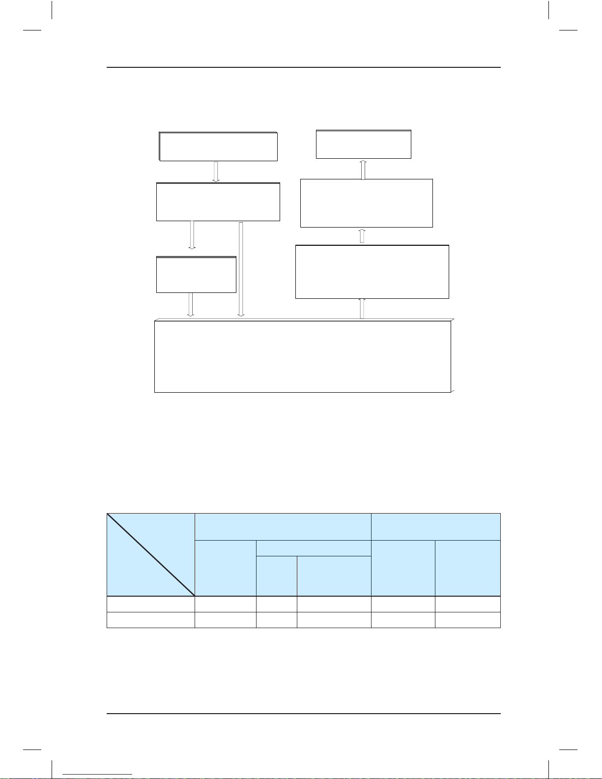
4.3.3 Summary of Commissioning at Inspection Speed
■ Asynchronous Motor Auto-tuning Process
Figure 4-3 Auto-tuning process of the asynchronous motor
The motor does not run with electromagnetism
noise. The controller automatically meansures
F1-06, F1-07 and F1-08 and calculates F1-09
and F1-10.
The motor runs. The controller
automatically measures F1-06, F1-07,
F1-08, F1-09 and F1-10.
Set F1-01, F1-02, F1-03, F1-04 and F1-05 based on
motor nameplate parameters
The tuning is complete. Set F0-01 to 1 to restore distance control.
Set F0-01 to 0 (Operation panel control)
Lift the car up (take off the rope from the motor)
The TUNE indicator on the operation panel is
ON (the circuit from the output side to motor is
energized ). Open the brake manually and
press RUN. The RUN indicator is ON and
motor tuning begins.
F1-11 = 1 F1-11 = 2
The car need not be lifted up. The TUNE
indicator on the operation panel is ON (the
circuit from the output side to the motor is
energized ). Press RUN. The RUN indicator is
ON and motor tuning begins.
With-load
tuning
No-load
tuning
Page 44
Brief NICE3000 Instruction Manual Use of the NICE3000
- 43 -
■ PMSM Auto-tuning Process
Figure 4-4 Auto-tuning process of the PMSM
If no-load tuning is adopted , set F1-11 to 2. The TUNE indicator on the operation
panel is ON. Open the brake manually and press RUN . The RUN indicator on the
operation panel is ON . The motor tuning begins .
If with-load tuning is adopted , set F1-11 to 1. The TUNE indicator on the
operation panel is ON . Press the inspection key and then press the UP or DOWN
key. The RUN indicator on the operation panel is ON . The motor tuning begins .
Properly set encoder
parameters F 1-00 and F1-12,
and motor parameters F 1-01,
F1-02, F1-03, F1-04 and F 1-05
Tuning is complete. Press RUN to
check whether the motor runs
normally . If not, please reverse the
encoder signal direction and
perform motor tuning again .
Set F0-01 to 0 (N o-load tuning )
or 1 (With-load tuning )
Life the car up and
disconnect the
motor from load
Set F0-01 to 1 to restore
distance control.
Resume the rope .
No-load
tuning
With-load
tuning
Values of F1-06 and F 1-08 are obtained .
Three or more times of tuning is
suggested . The value deviation of F 1-06
shall be within ±5°. The values of F 1-08
shall be the same.
F1-11 = 1
F1-11 = 2
■ Output Status of RUN and Brake Contactors
For the sake of safety in different control modes, the system handles the output commands
to the RUN contactor or brake contactor differently. In some situations, it is necessary to
release the running contactor or the brake contactor manually.
The following table lists the output status of the running and brake contactors.
Table 4-2 Output status of the running and brake contactors
Control
Mode
Output
State
Motor Auto-tuning (F1-11 = 1, 2)
Controller Running
(Not Auto-tuning)
No-load
Auto-tuning
With-load Auto-tuning
Operation
Panel
Control
(F0-01 = 0)
Distance
Control
(F0-01 = 1)
PMSM
Asynchronous
Motor
RUN contactor Output Output Output Not output Output
Brake contactor Not output Output Not output Not output Output
Page 45

Use of the NICE3000 Brief NICE3000 Instruction Manual
- 44 -
4.3.4 Commissioning at Normal Speed
After ensuring that running at inspection speed is normal, you can start commissioning at
normal speed. Shaft auto-tuning is required before the commissioning at normal speed.
Ensure that the elevator satisfies the safety running requirements.
To perform shaft auto-tuning, the following conditions must be satisfied:
1. The signals of the encoder and leveling sensors (NC, NO) are correct and the position
switches are installed properly.
2. The elevator is at the bottom floor and the down slow-down switch acts.
3. The elevator is in the inspection state. The control mode is distance control and CLVC
(F0-00 = 1, F0-01 = 1).
4. The top floor number (F6-00) and bottom floor number (F6-01) are set correctly.
5. The NICE3000 system is not in the fault alarm state. If there is a fault at the moment,
press
STOP
RES
to reset the fault.
Then set F1-11 to 3 on the operation panel or set F7 to 1 on the keypad of the MCB, and
start shaft auto-tuning.
4.3.5 Riding Comfort
The riding comfort is an important factor of the elevator's overall performance. Improper
installation of mechanical parts and improper parameter settings will cause bad comfort.
Enhancing the riding comfort mainly involves adjustment of the controller output and the
elevator's mechanical construction.
■ Controller Output
The parameters that may influence the riding comfort are described in this part.
Function
Code
Parameter Name
Setting
Range
Default Description
F1-09
Current filter time
(PMSM)
0.00–40.00 0.00
It can reduce the lowerfrequency vertical jitter during
running.
F2-00
Speed loop
proportional gain 1
0–100 40
F2-00 and F2-01 are the PI
regulation parameters when
running frequency is lower
than F2-02 (Switchover
frequency 1). F2-03 and
F2-04 are the PI regulation
parameters when running
frequency is higher than F205 (Switchover frequency 2).
The regulation parameters
between F2-02 and F2-05 are
the weighted average value
of F2-00 & F2-01 and F2-03
& F2-04.
F2-01
Speed loop integral
time 1
0.01–10.00s 0.60s
F2-02
Switchover
frequency 1
0.00 to F2-05 2.00 Hz
F2-03
Speed loop
proportional gain 2
0–100 35
F2-04
Speed loop integral
time 2
0.01–10.00s 0.80s
F2-05
Switchover
frequency 2
F2-02 to
F0-06
5.00 Hz
Page 46

Brief NICE3000 Instruction Manual Use of the NICE3000
- 45 -
For a faster system response, increase the proportional gain and reduce the integral gain.
Be aware that a fast system response causes system oscillation.
Figure 4-5 Relationship between switchover frequencies
PI regulation
parameter
Frequency
reference
F2-05
F2-02
F2-03
F2-04
F2-00
F2-01
The recommended regulating method is as follows:
If the factory parameters cannot satisfy the requirements, make slight regulation. Increase
the proportion gain first to the biggest value under which the system does not oscillate. Then
decrease the integral time to ensure fast responsiveness and small overshoot.
If both F2-02 (Switchover frequency 1) and F2-05 (Switchover frequency 2) are set to 0
simultaneously, only F2-03 and F2-04 are valid.
Function
Code
Parameter
Name
Setting
Range
Default Description
F2-06
Current loop
proportion gain
10–500 60
F2-06 and F2-07 are the
current loop adjustment
parameters in the vector
control algorithm.
F2-07
Current loop
integral gain
10–500 30
Regulating the two parameters for PMSM has obvious effect on the riding comfort.
Appropriate regulation can restrain jitter during running. Generally, increase their default
value to 180 and 60 respectively for the PMSM.
Function
Code
Parameter
Name
Setting Range Default Description
F3-00 Startup speed 0.000–0.030 m/s 0.010 m/s
It can reduce improve the
terrace feeling at startup
caused by the breakout friction
of guide rail.
F3-01
Startup speed
holding time
0.000–0.500s 0.150s
F3-18
Zero-speed
control time at
startup
0.000–1.000s 0.200s
It specifies the zero speed
holding time before brake
output.
Page 47
Use of the NICE3000 Brief NICE3000 Instruction Manual
- 46 -
Function
Code
Parameter
Name
Setting Range Default Description
F3-19
Brake release
delay
0.000–1.000s
0.200s
0.600s
It specifies the time required
from when the system outputs
the open signal to when the
brake is completely released.
The value is automatically
changed to 0.0600s by the
system when F8-02 is 2.
F3-20
Brake apply
delay
0.000–1.000s 0.300s
It specifies the time from when
the system outputs the close
signal to when the brake is
completely applied.
F8-11
Zero-speed
control time at
end
0.200–1.500s 0.200s
It specifies the zero speed
holding time after the brake is
applied.
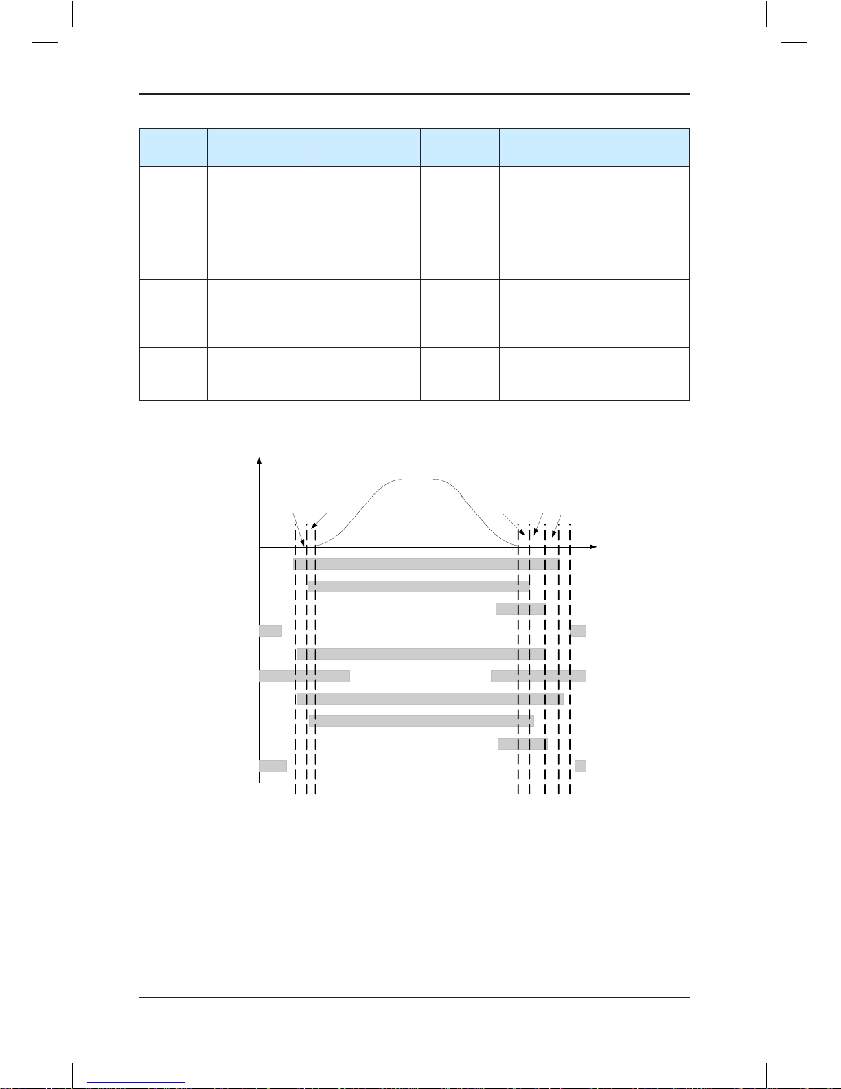
Figure 4-6 Running time sequence
V (speed )
RUN contactor
Brake contactor
Shorting door lock
circuit c ontactor
Shorting motor
stator contac tor
Internal
running status
Leveling signal
RUN contactor
feedback
Brake contactor
feedback
Shorting door lock circuit
contactor feedback
Shorting motor stator
contactor feedback
RUN contactor
Brake contactor
Shorting door lock
circuit c ontactor
Shorting motor
stator contac tor
Internal running status
Leveling signal
RUN contactor feedback
Brake contactor feedback
Shorting door lock circuit
contactor feedback
Shorting motor stator
contactor feedback
F3-18 F3-19 F3-20 F8-11
300 ms
The open time of the brakes varies according to the types and the response time of the
brakes is greatly influenced by the ambient temperature. Too high brake coil temperature
slows the brake responsiveness. Thus, when the riding comfort at startup or stop cannot
be improved by adjusting zero servo or load cell compensation parameters, appropriately
increase F3-19 and F3-20 to check whether the brake release time influences the riding
comfort.
Page 48

Brief NICE3000 Instruction Manual Use of the NICE3000
- 47 -
Function
Code
Parameter Name Setting Range Default
F8-01 Pre-torque selection
0: Pre-torque invalid
1: Load cell pre-torque
compensation
2: Automatic pre-torque
compensation
0
F8-02
Pre-torque offset
Zero servo current coefficient
0.0%–100.0%
0.20%–50.0%
50.0%
15.0%
F8-03
Drive gain
Zero servo speed loop KP
0.00–2.00
0.00–1.00
0.60
0.50
F8-04
Brake gain
Zero servo speed loop TI
0.00–2.00
0.00–2.00
0.60
0.60
1: Load cell pre-torque compensation
The controller with the load cell sensor pre-outputs the torque matched the load so as to
ensure the riding comfort of the elevator.
• Motor driving status: full-load up, no-load down
• Motor braking status: full-load down, no-load up
"Pre-torque offset" is actually the elevator balance coefficient, namely, the percentage of car
load to rated load when the car cage and counterweight are balanced.
The drive gain or brake gain scales the elevator's current pre-torque coefficient when the
motor runs at the drive or brake side. If the gain set is higher, then the calculated value of
startup pro-torque compensation is higher. The controller identifies the braking or driving
state according to the load cell sensor signal and automatically calculates the required
torque compensation value.
When an analog device is used to measure the load, these parameters are used to adjust
the elevator startup. To adjust the startup, do as follows:
• In the driving state, increasing the value of F8-03 could reduce the rollback during the
elevator startup, but a too high value could cause car lurch at start.
• In braking state, increasing the value of F8-04 could reduce the jerk in command
direction during the elevator startup, but a too high value could cause car lurch at start.
2: Automatic pre-torque compensation
This function is enabled only when the ERN1387 or ECN1313 encoder is applied. The
system automatically adjusts the compensated torque at startup.
a. Gradually increase F8-02 (Zero servo current coefficient) until that the rollback or jerk
in command direction is cancelled at brake release and the motor does not vibrate.
b. Increase the value of F8-02 (Zero servo current coefficient) if the motor jitters when F8-
04 (Zero servo speed loop TI) is less than 1.00.
c. Motor vibration and acoustic noise indicate excessive value of F8-03 (Zero servo speed
loop KP). Use the default value of F8-03.
Page 49

Use of the NICE3000 Brief NICE3000 Instruction Manual
- 48 -
■ Mechanical Construction
The mechanical construction affecting the riding comfort involves the guide rail, guide shoe,
steel rope, installation of the brake, balance of the car and the resonance caused by the
car, guild rail and motor. For asynchronous motor, abrasion or improper installation of the
gearbox may arouse bad riding comfort.
1. Installation of the guide rail mainly involves the verticality of the rail, rail surface flatness,
smoothness of the guide rail connection and parallelism between two guide rails
(including rails at the counterweight side).
2. The tightness of the guide shoes (including the one at the counterweight side) also
influences the riding comfort. The guide shoes must not be too loose or tight.
3. The drive from the motor to the car totally depends on the steel rope. Too big flexibility of
the steel rope with irregular resistance during the car running may cause curly oscillation
of the car. In addition, unbalanced stress of multiple steel ropes may cause the car to
jitter during running.
4. The riding comfort may be influenced during running if the brake arm is installed too
tightly or the brake is released incompletely.
5. If the car weight is unbalanced, it will cause uneven stress of the guide shoe that
connects the car and the guide rail. As a result, the guide shoe will rub with the guide
rail during running, affecting the riding comfort.
6. For asynchronous motor, abrasion or improper installation of the gearbox may also
affect the riding comfort.
7. Resonance is an inherent character of a physical system, related to the material and
quality of system components. If you are sure the oscillation is caused by resonance,
reduce the resonance by increasing/decreasing the car weight or counterweight and
add resonance absorbers at connections of the components. For example, place rubber
blanket under the motor.
4.3.6 Door Machine Commissioning
As shown in the second figure in section 4.1, correlation of the door machine controller
and the elevator controller is that the CTB outputs door open/close command and the door
machine controller feeds back the door open/close limit signal.
After commissioning and installation of the door machine are complete, check whether the
wiring is correct and the door open/close limit signals are consistent with the default setting.
To perform the door machine commissioning, do as follows:
1. In the terminal control mode of the door machine controller, manually short the door
open relay output terminal BM/B1 and the door close relay output terminal BM/B2 on
the CTB and observe whether the door machine can open and close correspondingly.
If the door machine cannot act properly, check whether BM/B1 and BM/B2 are
wrongly connected to the input terminals of the door machine controller and whether
commissioning of the door machine controller is complete.
Page 50

Brief NICE3000 Instruction Manual Use of the NICE3000
- 49 -
2. After ensuring that control of door open/close is normal, check whether the door open/
close signal feedback from the door machine is normal.
As shown in the following figure which is part of display of parameter F5-35 on the
operation panel, segments E and C of the upmost right 7-segment LED are the
monitoring points of door open limit and door close limit.
• Segment C ON, segment E OFF: The system receives the door open limit signal
and the door is in the open state.
• Segment E ON, segment C OFF: The system receives the door close limit signal
and the door is in the close state.
The two segments should be off in the door open/close process.
Control the door in the open or close state manually and query parameter F5-35. If the
following screen is displayed, it indicates that the door machine controller feeds back the
correct door open and close signals.
Figure 4-7 Monitoring the door open and close limit signals
12345
A
B
C
D
E
F
G
DP
A
B
C
D
E
F
G
DP
4.3.7 Password Setting
The NICE3000 controller provides the parameter password protection function. Here gives
an example of changing the password into 12345, as shown in the following figure.
Figure 4-8 Example of changing the password
000000
FP-00FP
ENTER
000000
100001000012000
1200012300
0.000 F0
PRG ENTER
12300 12340 12340 FP-00
Data display
ENTER
12345
After you set the user password (set FP-00 to a non-zero value), the system requires user
password authentication (the system displays "------") when you press PRG. In this case,
you can modify the function code parameters only after entering the password correctly.
Page 51

Use of the NICE3000 Brief NICE3000 Instruction Manual
- 50 -
In the password protection unlocked status, you can change the password at any time. The
last input number will be the user password.
If you want to disable the password protection function, enter the correct password and then
set FP-00 to 0. If FP-00 is a non-zero value at power-on, the parameters are protected by
the password.
Page 52

5
Function Code Table
Page 53

Function Code Table Brief NICE3000 Instruction Manual
- 52 -
Chapter 5 Function Code Table
Function
Code
Parameter Name Setting Range Default
Group F0: Basic parameters
F0-00 Control mode
0: Sensorless flux vector control
(SFVC)
1:Closed-loop vector control (CLVC)
1
F0-01 Command source selection
0: Operation panel control
1: Distance control
1
F0-02
Speed reference in operation
panel control
0.050 m/s to F0-04 0.050 m/s
F0-03
Maximum elevator running
speed
0.250 m/s to F0-04 1.600 m/s
F0-04 Rated elevator speed 0.250–4.000 m/s 1.600 m/s
F0-05 Rated elevator load 300–9999 kg 1000 kg
F0-06 Maximum frequency 20.00–99.00 Hz 50.00 Hz
F0-07 Carrier frequency 0.5–16.0 kHz 6 kHz
Group F1: Motor parameters
F1-00 Encoder type selection
0: SIN/COS incremental encoder
1: UVW incremental encoder
1
F1-01 Rated motor power 1.1–75.0 kW
Model
dependent
F1-02 Rated motor voltage 0–440 V 380 V
F1-03 Rated motor current 0.00–655.00 A
Model
dependent
F1-04 Rated motor frequency 0.00–99.00 Hz 50.00 Hz
F1-05 Rated motor rotational speed 0–3000 RPM 1460 RPM
F1-06
Stator resistance
(asynchronous motor)
0.000–30.000 Ω
Model
dependent
Encoder initial angle (PMSM) 0–359.9°
F1-07
Rotor resistance 0.000–30.000 Ω
Model
dependent
Encoder angle at power-off
(PMSM)
0–359.9°
F1-08
Leakage inductance
(asynchronous motor)
0.00–300.00 mH
Model
dependent
Wiring mode (PMSM) 0–15
F1-09
Mutual inductance 0.1–3000.0 mH
Model
dependent
Current filter time (PMSM) 0.00–40.00
F1-10
Motor magnetizing current 0.01–300.00 A
Model
dependent
Selection of encoder's signal
check (PMSM)
0–255
Page 54

Brief NICE3000 Instruction Manual Function Code Table
- 53 -
Function
Code
Parameter Name Setting Range Default
F1-11 Auto-tuning mode selection
0: No operation
1: With-load auto-tuning
2: No-load auto-tuning
3: Shaft auto-tuning
0
F1-12 Encoder lines per revolution 0–10000 1024
F1-13 Encoder fault detection time 0.0–10.0s 1.0s
Group F2: Vector control parameters
F2-00 Speed loop proportional gain 1 0–100 40
F2-01 Speed loop integral time 1 0.01–10.00s 0.60s
F2-02 Switchover frequency 1 0.00 to F2-05 2.00 Hz
F2-03 Speed loop proportional gain 2 0–100 35
F2-04 Speed loop integral time 2 0.01–10.00s 0.80s
F2-05 Switchover frequency 2 F2-02 to F0-06 5.00 Hz
F2-06 Current loop proportional gain 10–500 60
F2-07 Current loop integral gain 10–500 30
F2-08 Torque limit 0.0–200.0% 150.0%
F2-10 Elevator running direction
0: Running direction and position
pulse direction unchanged
1: Running direction reversed,
position pulse direction reversed
2: Running direction unchanged,
position pulse direction reversed
3: Running direction reversed,
position pulse direction unchanged
0
Group F3: Running control parameters
F3-00 Startup speed 0.000–0.030 m/s 0.010 m/s
F3-01 Startup speed holding time 0.000–0.500s 0.150s
F3-02 Acceleration rate 0.200–2.000 m/s
2
0.600 m/s
2
F3-03 Acceleration start jerk time 0.300–4.000s 2.500s
F3-04 Acceleration end jerk time 0.300–4.000s 2.500s
F3-05 Deceleration rate 0.200–2.000 m/s
2
0.600 m/s
2
F3-06 Deceleration start jerk time 0.300–4.000s 2.500s
F3-07 Deceleration end jerk time 0.300–4.000s 2.500s
F3-08 Special deceleration rate 0.500–2.000 m/s
2
0.900 m/s
2
F3-09 Pre-deceleration distance 0–90.0 mm 0.0 mm
F3-10 Re-leveling speed 0.000–0.080 m/s 0.040 m/s
F3-11 Inspection speed 0.100–0.630 m/s 0.250 m/s
F3-12 Position of up slow-down 1 0.00–300.00 m 0.00 m
Page 55

Function Code Table Brief NICE3000 Instruction Manual
- 54 -
Function
Code
Parameter Name Setting Range Default
F3-13 Position of down slow-down 1 0.00–300.00 m 0.00 m
F3-14 Position of up slow-down 2 0.00–300.00 m 0.00 m
F3-15 Position of down slow-down 2 0.00–300.00 m 0.00 m
F3-16 Position of up slow-down 3 0.00–300.00 m 0.00 m
F3-17 Position of down slow-down 3 0.00–300.00 m 0.00 m
F3-18
Zero-speed control time at
startup
0.000–1.000s 0.200s
F3-19 Brake release delay 0.000–1.000s
0.200s
0.600s
F3-20 Brake apply delay 0.000–1.000s 0.300s
Group F4: Floor parameters
F4-00 Leveling adjustment 0–60 mm 30 mm
F4-01 Current floor F6-01 to F6-00 1
F4-02
High byte of current floor
position
0–65535 1
F4-03
Low byte of current floor
position
0–65535 34464
F4-04 Length 1 of leveling flag 0–65535 0
F4-05 Length 2 of leveling flag 0–65535 0
F4-06 High byte of floor 1 height 0–65535 0
F4-07 Low byte of floor 1 height 0–65535 0
F4-08 High byte of floor 2 height 0–65535 0
F4-09 Low byte of floor 2 height 0–65535 0
F4-10 High byte of floor 3 height 0–65535 0
F4-11 Low byte of floor 3 height 0–65535 0
·
·
·
F4-62 High byte of floor 29 height 0–65535 0
F4-63 Low byte of floor 29 height 0–65535 0
F4-64 High byte of floor 30 height 0–65535 0
F4-65 Low byte of floor 30 height 0–65535 0
Group F5: Terminal function parameters
F5-00
Attendant/Normal switchover
time
3–200s 3
Page 56

Brief NICE3000 Instruction Manual Function Code Table
- 55 -
Function
Code
Parameter Name Setting Range Default
F5-01 X1 function selection NO input: 01–31
00: No function
01: Up leveling signal
02: Down leveling signal
03: Door zone signal
04: Safety circuit feedback signal
05: Door lock circuit feedback signal
06: Running feedback signal
07: Brake feedback signal
08: Inspection signal
09: Inspection up signal
10: Inspection down signal
11: Fire emergency signal
12: Up limit signal
13: Down limit signal
14: Over-load signal
15: Full-load signal
16: Up slow-down 1 signal
17: Down slow-down 1 signal
18: Up slow-down 2 signal
19: Down slow-down 2 signal
20: Up slow-down 3 signal
21: Down slow-down 3 signal
22: Shorting door lock circuit
contactor feedback
23: Firefighter switch signal
24: Door machine 1 light curtain
signal
25: Door machine 2 light curtain
signal
26: Brake travel switch feedback
signal
27: UPS valid signal
28: Elevator locked signal
29: Safety circuit 2 feedback signal
30: Shorting PMSM stator feedback
signal
31: Door lock circuit 2 feedback
signal
(To be continued)
33
F5-02 X2 function selection 35
F5-03 X3 function selection 34
F5-04 X4 function selection 04
F5-05 X5 function selection 05
F5-06 X6 function selection 38
F5-07 X7 function selection 39
F5-08 X8 function selection 22
F5-09 X9 function selection 40
F5-10 X10 function selection 09
F5-11 X11 function selection 10
F5-12 X12 function selection 44
Page 57

Function Code Table Brief NICE3000 Instruction Manual
- 56 -
Function
Code
Parameter Name Setting Range Default
F5-13 X13 function selection NC input: 33–63
33: Up leveling signal
34: Down leveling signal
35: Door zone signal
36: Safety circuit feedback signal
37: Door lock circuit feedback signal
38: Running feedback signal
39: Brake feedback signal
40: Inspection signal
41: Inspection up signal
42: Inspection down signal
43: Fire emergency signal
44: Up limit signal
4513: Down limit signal
46: Over-load signal
47: Full-load signal
48: Up slow-down 1 signal
49: Down slow-down 1 signal
50: Up slow-down 2 signal
51: Down slow-down 2 signal
52: Up slow-down 3 signal
53: Down slow-down 3 signal
54: Shorting door lock circuit
contactor feedback
55: Firefighter switch signal
56: Door machine 1 light curtain
signal
57: Door machine 2 light curtain
signal
58: Brake travel switch feedback
59: UPS valid signal NC input
60: Elevator locked signal
61: Safety circuit 2 feedback
62: Shorting PMSM stator contactor
feedback
63: Door lock circuit 2 feedback
45
F5-14 X14 function selection 48
F5-15 X15 function selection 49
F5-16 X16 function selection 50
F5-17 X17 function selection 51
F5-18 X18 function selection 00
F5-19 X19 function selection 00
F5-20 X20 function selection 00
F5-21 X21 function selection 00
F5-22 X22 function selection 00
F5-23 X23 function selection 00
F5-24 X24 function selection 00
Page 58

Brief NICE3000 Instruction Manual Function Code Table
- 57 -
Function
Code
Parameter Name Setting Range Default
F5-25 CTB input type selection 0–255 64
The NO/NC setting of terminals X1 to X8 on the CTB is listed in the following table.
Terminal Bit Parameter Name Default
X1 Bit0 Door 1 light curtain 0
X2 Bit1 Door 2 light curtain 0
X3 Bit2 Door 1 open limit 0
X4 Bit3 Door 2 open limit 0
X5 Bit4 Door 1 close limit 0
X6 Bit5 Door 2 close limit 0
X7 Bit6 Full-load signal 1
X8 Bit7 Over-load signal 0
0: NC
1: NO
F5-26 Y1 function selection Output function:
0: No function
1: RUN contactor control
2: Brake contactor control
3: Shorting door lock circuit contactor
4: Fire emergency floor arrival signal
feedback
5: Door 1 open
6: Door 1 close
7: Door 2 open
8: Door 2 close
9: Brake and RUN contactors healthy
10: Fault state
11: Running monitor
12: Shorting PMSM stator
13: Emergency evacuation operation
14: System healthy
15: Emergency buzzer control
16: High-voltage startup of brake
17: Elevator running in up direction
18: Fan and lamp
1
F5-27 Y2 function selection 2
F5-28 Y3 function selection 3
F5-29 Y4 function selection 4
F5-30 Y5 function selection 0
F5-31 Y6 function selection 0
Page 59

Function Code Table Brief NICE3000 Instruction Manual
- 58 -
Function
Code
Parameter Name Setting Range Default
F5-32 Communication status display
Figure 5-1 Communication status display
12345
CANbu s
Modbus for hall call at ea ch floor
A
B
C
D
E
F
G
DP
A
B
C
D
E
F
G
DP
A
B
C
D
E
F
G
DP
A
B
C
D
E
F
G
DP
The upmost left 7-segment LED is expressed by 0–9, and used for CAN communication
monitoring.
• 0: communication normal
• 9: communication interrupted completely
The eight segments A/B/C/D/E/F/G/DP of the four 7-segment LEDs from right to left successively
indicate each HCB Modbus communication monitoring of each HCB.
• ON: The Modbus communication of the HCB for the floor is normal.
• OFF: The Modbus communication of the HCB for the floor is interrupted.
F5-33 Program control selection
• Bit0 to Bit3: Reserved
• Bit4: Arrival gong disabled at night
• (22:00 p.m. to 7:00 a. m.)
• Bit5: Input function 25/27 used
as motor overheat or earthquake
detection input
• Bit6: Door lock disconnected
added once to the prerequisites
from inspection to normal running
• Bit7: Fault code not displayed on
the keypad
• Bit8: Door open command
cancelled immediately at door
open limit
• Bit9: Car stop due to zero-speed
torque holding when the travel
switch of the brake is abnormal
• Bit10 to Bit15: Reserved
0
F5-34 Terminal state display
F5-35 Terminal state display
F5-34/F5-35 indicates the state of the I/O terminals. The serial numbers of the five 7-segment
LEDs are 5, 4, 3, 2 and 1 from left to right, shown as below:
Page 60

Brief NICE3000 Instruction Manual Function Code Table
- 59 -
Function
Code
Parameter Name Setting Range Default
F5-34 F5-35
SN Segment Indication SN Segment Indication
1 1
A Light curtain 1
B Up leveling signal B Light curtain 2
C Down leveling signal C Door 1 open limit
D Door zone signal D Door 2 open limit
E Safety circuit feedback 1 E Door 1 close limit
F Door lock circuit feedback 1 F Door 2 close limit
G Running contactor feedback G Full-load signal
DP Brake contactor feedback 1 DP Over-load signal
2
A Inspection signal
2
A Door open button
B I
nspection up signal B Door close button
C Inspection down signal C Door open delay button
D Fire emergency signal D Bypass signal
E Up limit signal E Attendant signal
F Down limit signal F Direction change signal
G Over-load signal G
Independent running
signal
DP Full-load signal DP
Firefighter operation
signal
3
A Up slow-down 1 signal
3
A Door open output 1
B Down slow-down 1 signal B Door close output 1
C Up slow-down 2 signal C Door
lock signal
D Down slow-down 2signal D Door open output 1
E Up slow-down 3 signal E Door close output 2
F Down slow-down 3 signal F Door lock signal
G
Shorting door lock circuit
contactor feedback
G Up arrival gong
DP Motor overheat signal DP Down arrival gong
Page 61

Function Code Table Brief NICE3000 Instruction Manual
- 60 -
Function
Code
Parameter Name Setting Range Default
4
A Door machine 1 light curtain
4
A Door open button display
B Door machine 2 light curtain B Door close button display
C Brake feedback 2 C
Door open delay button
display
D UPS input D Bypass sign
E Elevator locked input E Reserved
F Safety circuit feedback 2 F Buzzer output
G
Shorting PMSM stator
contactor feedback
G Reserved
DP Door lock circuit feedback 2 DP Energy saving sign
5
A Reserved
5
A
System light curtain state
1
B RUN co
ntactor output B
System light curtain state
2
C Brake contactor output C
Hall call elevator-locked
input
D
Shorting door lock circuit
contactor control
D
Hall call fire emergency
input
E
Fire emergency floor arrival
signal
E Full-load signal
F Over-load signal
F5-36 Load cell input selection
0: MCB digital input
1: CTB digital input
2: CTB analog input
3: MCB analog input
2
Group F6: Basic elevator parameters
F6-00 Top floor of the elevator F6-01 to 31 9
F6-01 Bottom floor of the elevator 1 to F6-00 1
F6-02 Parking floor F6-01 to F6-00 1
F6-03 Fire emergency floor F6-01 to F6-00 1
F6-04 Elevator-locked floor F6-01 to F6-00 1
F6-05 Service floors 1 0–65535 (floors 1–16) 65535
F6-06 Service floors 2 0–65535 (floors 17–31) 65535
F6-07
Number of elevators in group
mode
1–8 1
F6-08 Elevator SN 1–8 1
Page 62
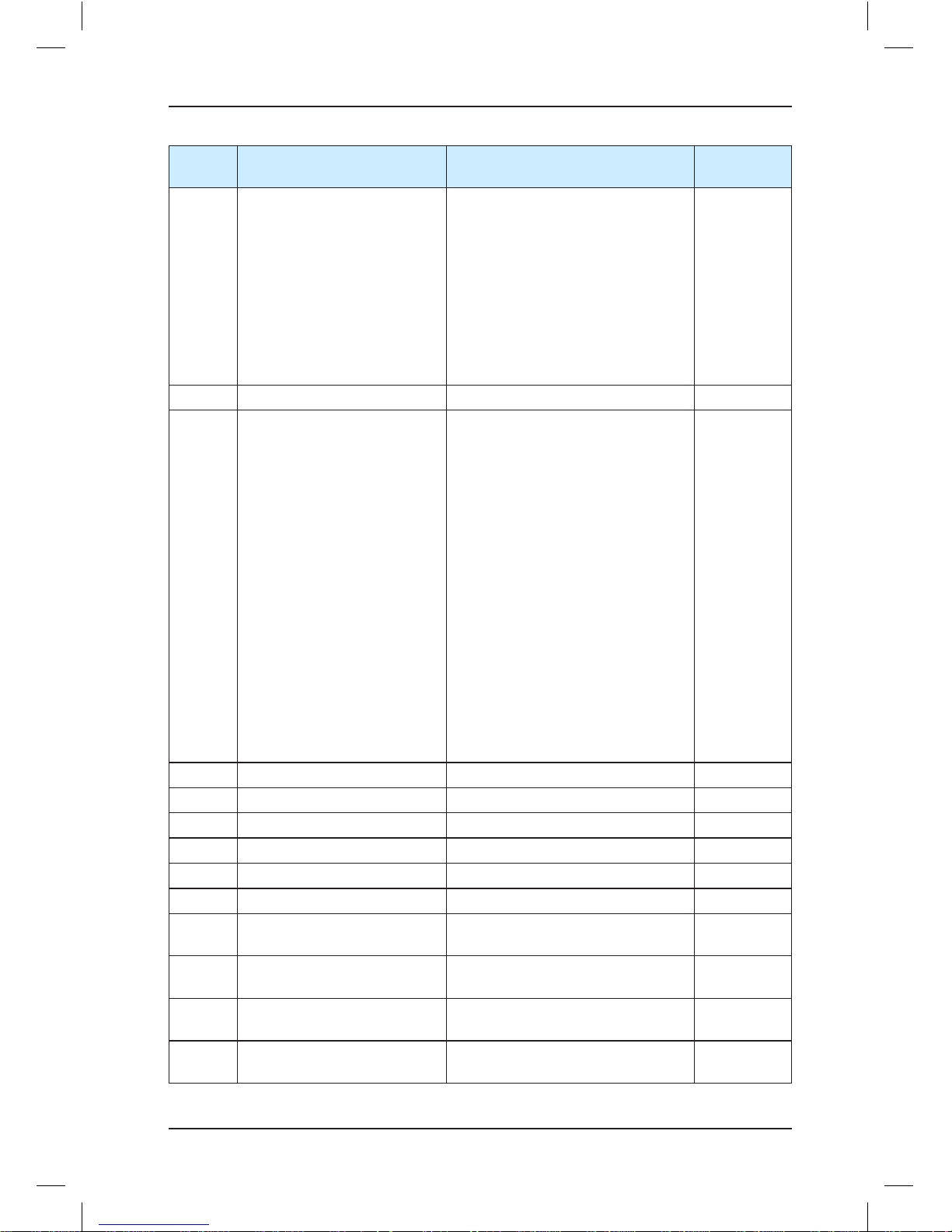
Brief NICE3000 Instruction Manual Function Code Table
- 61 -
Function
Code
Parameter Name Setting Range Default
F6-09 Parallel selection
• Bit0: Dispersed waiting
• Bit1: Reserved
• Bit2: Parallel implemented at
monitoring port
• Bit4: Door not open at power-on if
elevator-locked signal is enabled
• Bit6: Clear floor number and
display direction in advance
• Bit7: New anti-nuisance function
Bit14: Safety 2, door lock 2 time
interval detection
0
F6-10 Leveling sensor filter time 10–50 ms 14 ms
F6-11 Elevator function selection
• Bit1: Returning to base floor for
large position deviation function
• Bit2: Cancelling auto sequential
arrange of floor addresses to be
displayed
• Bit3: Stopping shorting motor
stator output at door open after
auto slide
• Bit4: Current slope mode at stop
for 300 ms
• Bit5: Current detection valid at
startup for PMSM
• Bit7: Door open valid at non-door
zone in the inspection state
• Bit8: Door open and close once
after inspection turned to normal
• Bit10: Buzzer not tweet upon re-
leveling
• Bit11: Super short floor function
• Bit13: E53 fault auto reset
0
F6-12 VIP floor F6-01 to F6-00 0
F6-13 Security floor F6-01–F6-00 1
F6-14 Down-collective 1 start time 00.00–23.59 (hour.minute) 00.00
F6-15 Down-collective 1 end time 00.00–23.59 (hour.minute) 00.00
F6-16 Down-collective 2 start time 00.00–23.59 (hour.minute) 00.00
F6-17 Down-collective 2 end time 00.00–23.59 (hour.minute) 00.00
F6-18
Time-based floor service 1
start time
00.00–23.59 (hour.minute) 00.00
F6-19
Time-based floor service 1 end
time
00.00–23.59 (hour.minute) 00.00
F6-20
Floor 1 of time-based floor
service 1
0–65535 (floors 1–16) 65535
F6-21
Floor 2 of time-based floor
service 1
0–65535 (floors 17–31) 65535
Page 63
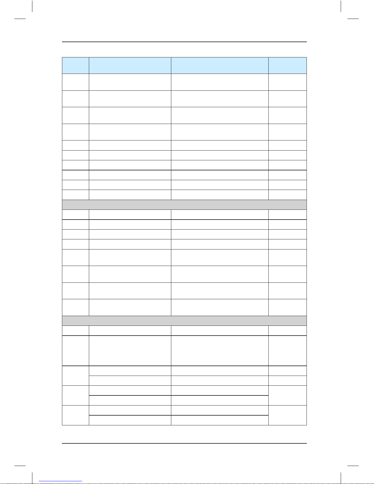
Function Code Table Brief NICE3000 Instruction Manual
- 62 -
Function
Code
Parameter Name Setting Range Default
F6-22
Time-based floor service 2
start time
00.00–23.59 (hour.minute) 00.00
F6-23
Time-based floor service 2 end
time
00.00–23.59 (hour.minute) 00.00
F6-24
Floor 1 of time-based floor
service 2
0–65535 (floors 1–16) 65535
F6-25
Floor 2 of time-based floor
service 2
0–65535 (floors 17–31) 65535
F6-26 Peak 1 start time 00.00–23.59 (hour.minute) 00.00
F6-27 Peak 1 end time 00.00–23.59 (hour.minute) 00.00
F6-28 Peak 1 floor F6-01–F6-00 1
F6-29 Peak 2 start time 00.00–23.59 (hour.minute) 00.00
F6-30 Peak 2 end time 00.00–23.59 (hour.minute) 00.00
F6-31 Peak 2 floor F6-01–F6-00 1
Group F7: Test function parameters
F7-00 Test floor 1 0–top floor of the elevator (F6-00) 0
F7-01 Test floor 2 0–top floor of the elevator (F6-00) 0
F7-02 Test floor 3 0–top floor of the elevator (F6-00) 0
F7-03 Random test times 0–60000 0
F7-04 Hall call enabled
0: Hall call allowed
1: Hall call prohibited
0
F7-05 Door open enabled
0: Door open allowed
1: Door open prohibited
0
F7-06 Over-load function selection
0: Over-load running prohibited
1: Over-load running allowed
0
F7-07 Limit switch
0: Limit switch enabled
1: Limit switch disabled
0
Group F8: Enhanced function parameters
F8-00 Load cell auto-tuning 0–100% 0%
F8-01 Pre-torque selection
0: Pre-torque invalid
1: Load cell pre-torque compensation
2: Automatic pre-torque
compensation
0
F8-02
Pre-torque offset 0.0–100.0% 50.0%
Zero servo current coefficient 0.20%–50.0% 15.0%
F8-03
Drive gain 0.00–2.00
0.60
0.50
Zero servo speed loop KP 0.00–1.00
F8-04
Brake gain 0.00–2.00
0.60
0.60
Zero servo speed loop TI 0.00–2.00
Page 64

Brief NICE3000 Instruction Manual Function Code Table
- 63 -
Function
Code
Parameter Name Setting Range Default
F8-05 Current car load 0–1023 0
F8-06 Car no-load load 0–1023 0
F8-07 Car full-load load 0–1023 100
F8-08 Anti-nuisance function
0: Disabled
1: Enabled (load cell sensor required)
0
F8-09
Emergency evacuation
operation speed at power
failure
0.000–0.100 m/s 0.050 m/s
F8-10
Emergency evacuation
operation mode at power
failure
0: Motor not running
1: UPS
2: 48 V battery power supply
0
F8-11 Zero-speed control time at end 0.200–1.500s 0.200
Group F9: Time parameters
F9-00
Time for idle elevator to return
to base floor
0–240 minutes 10 minutes
F9-01
Time for fan and lamp to be
turned off
0–240 minutes 2 minutes
F9-02
Maximum floor running time
interval
0–45s (invalid under 3s) 45s
F9-03 Clock: year 2000–2100 Current time
F9-04 Clock: month 1–12 Current time
F9-05 Clock: day 1–31 Current time
F9-06 Clock: hour 0–23 Current time
F9-07 Clock: minute 0–59 Current time
F9-09 Accumulative running time 0–65535 hours 0
F9-11 High byte of running times 0–9999 0
F9-12 Low byte or running times 0–9999 0
Group FA: Keypad setting parameters
FA-00 Keypad display selection
0: Reversed display, physical floor
1: Positive display, physical floor
2: Reversed display, hall call data
3: Positive display, hall call data
0
FA-01 Run display 1 1–65535 65535
FA-02 Stop display 1–65535 65535
FA-03 Current encoder angle 0.0–360.0° 0.0°
FA-04 Software 1 (FK) 0–65535 0
FA-05 Software 2 (ZK) 0–65535 0
FA-06 Software 3 (DSP) 0–65535 0
FA-07 Heatsink temperature 0–100°C 0°C
Page 65

Function Code Table Brief NICE3000 Instruction Manual
- 64 -
Function
Code
Parameter Name Setting Range Default
Group FB: Door function parameters
FB-00 Number of door machine (s) 1–2 1
FB-01 CTB software 0–99 0
FB-02
Service floor 1 of door machine
1
0–65535 (floors 1–16) 65535
FB-03
Service floor 2 of door machine
1
0–65535 (floors 17–31) 65535
FB-04
Service floor 1 of door machine 20–65535 (floors 1–16), valid only
when there are two door machines
65535
FB-05
Service floor 2 of door machine 20–65535 (floors 17–31), valid only
when there are two door machines
65535
FB-06 Open door time protection 5–99s 10s
FB-07 Arrival gong output delay 0–1000 0
FB-08 Close door time protection 5–99s 15s
FB-09 Times of door open and close 0–20 0
FB-10 Door state of idle elevator
• 0: close the door successfully
• 1: waiting with door open at base
floor
• 2: waiting with door open at each
floor
0
FB-11
Door open holding time for hall
call
1–30s 5s
FB-12
Door open holding time for car
call
1–30s 3s
FB-13
Door open holding time at base
floor
1–30s 10s
FB-14 Door open holding time 10–1000s 30s
Group FC: Protection function parameters
FC-00 Protection function selection
• Bit0: Detection of short circuit to
ground at power-on
• Bit1: Detection of inspection
startup current
1
FC-01 Protection function selection
• Bit0: Over-load protection selection
• Bit1: Output phase loss selection
• Bit2: Over-modulation function
selection
• Bit3: Reserved
• Bit4: Light curtain judgment at door
close limit
• Bit5: Cancelling DSP
communication check
• Bit6: Reserved
• Bit7: Stop at leveling position
function
1
Page 66
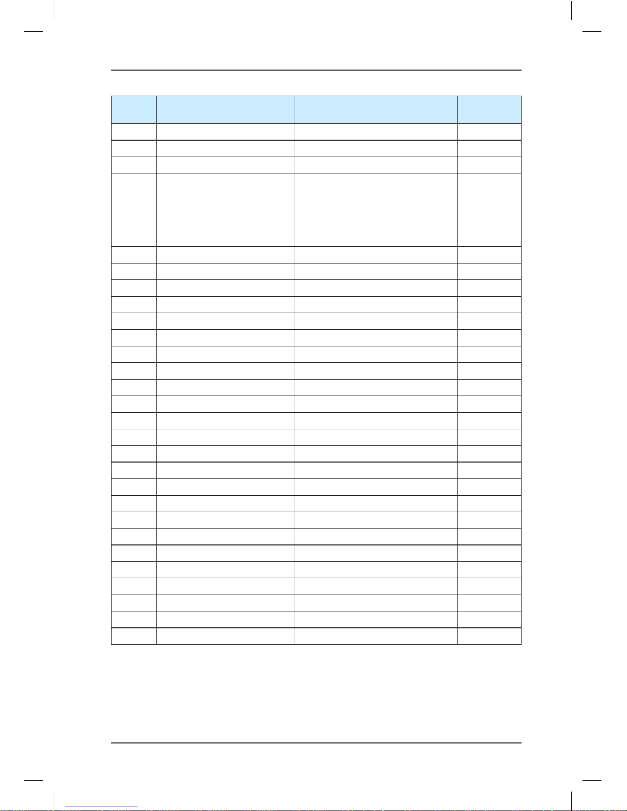
Brief NICE3000 Instruction Manual Function Code Table
- 65 -
Function
Code
Parameter Name Setting Range Default
FC-02 Over-load protection coefficient 0.50–10.00 1.00
FC-03 Over-load alarm coefficient 50–100% 80%
FC-04 Opposite door selection 1–10 0
FC-06 1st fault
The first two digits indicate the floor
and the last two digits indicate the
fault code. For example, if E30
(elevator position abnormal) occurs
at floor 1, the fault information is
0130.
0
FC-07 1st fault time (month/day) 0–1231 0
FC-08 2nd fault 0–3199 0
FC-09 2nd fault time (month/day) 0–1231 0
FC-10 3rd fault 0–3199 0
FC-11 3rd fault time (month/day) 0–1231 0
FC-12 4th fault 0–3199 0
FC-13 4th fault time (month/day) 0–1231 0
FC-14 5th fault 0–3199 0
FC-15 5th fault time (month/day) 0–1231 0
FC-16 6th fault 0–3199 0
FC-17 6th fault time (month/day) 0–1231 0
FC-18 7th fault 0–3199 0
FC-19 7th fault time (month/day) 0–1231 0
FC-20 8th fault 0–3199 0
FC-21 8th fault time (month/day) 0–1231 0
FC-22 9th fault 0–3199 0
FC-23 9th fault time (month/day) 0–1231 0
FC-24 10th fault 0–3199 0
FC-25 10th fault time (month/day) 0–1231 0
FC-26 Latest fault 0–3199 1
FC-27 Speed at latest fault 0.000–4.000 m/s 0.000
FC-28 Current at latest fault 0.0–999.9 A 0.0
FC-29 DC bus voltage at latest fault 0–999 V 0
FC-30 Latest fault time (month/day) 0–1231 0
Page 67

Function Code Table Brief NICE3000 Instruction Manual
- 66 -
Function
Code
Parameter Name Setting Range Default
FC-31 Latest fault time (hour/minute) 00.00–23.59 00.00
Group FD: Communication parameters
FD-00 Baud rate setting
0–5: 9600 bps
6: 19200 bps
7: 38400 bps
5
FD-01 Data format
0: No check-out, data format <8,N,2>
1: Even check-out, data format
<8,E,1>
2: Odd check-out, data format
<8,O,1>
0
FD-02 Local address
0–127
0: Broadcasting address
1
FD-03
Communication response
delay
0–20 ms 10 ms
FD-04 Communication timeout delay 0.0–60.0s, 0.0s: invalid 0.0s
FD-05 Stop delay upon re-leveling 0.00–2.00s 0.00s
Group FE: Elevator function parameters
FE-00 Collective selective mode
0: Full selective
1: Down selective
2: Up selective
0
FE-01 Floor 1 corresponding display 0000–1999
The first two digits indicate the
display code of ten's place, and the
last two digits indicate the display
code of unit's place.
00: display 0
01: display 1
02: display 2
03: display 3
04: display 4
05: display 5
(Contiued)
1901
FE-02 Floor 2 corresponding display 1902
FE-03 Floor 3 corresponding display 1903
FE-04 Floor 4 corresponding display 1904
FE-05 Floor 5 corresponding display 1905
FE-06 Floor 6 corresponding display 1906
FE-07 Floor 7 corresponding display 1907
Page 68

Brief NICE3000 Instruction Manual Overiew
- 67 -
Function
Code
Parameter Name Setting Range Default
FE-08 Floor 8 corresponding display 06: display 6
07: display 7
08: display 8
09: display 9
10: display A
11: display B
12: display G
13: display H
14: display L
15: display M
16: display P
17: display R
18: display 19: no display
20: display 12
21: display 13
22: display 23
23: display C
24: display D
25: display E
26: display F
27: display I
28: display J
29: display K
30: display N
31: display O
32: display Q
33: display S
34: display T
35: display U
36: display V
37: display W
38: display X
39: display Y
40: display Z
1908
FE-09 Floor 9 corresponding display 1909
FE-10 Floor 10 corresponding display 0100
FE-11 Floor 11 corresponding display 0101
FE-12 Floor 12 corresponding display 0102
FE-13 Floor 13 corresponding display 0103
FE-14 Floor 14 corresponding display 0104
FE-15 Floor 15 corresponding display 0105
FE-16 Floor 16 corresponding display 0106
FE-17 Floor 17 corresponding display 0107
FE-18 Floor 18 corresponding display 0108
FE-19 Floor 19 corresponding display 0109
FE-20 Floor 20 corresponding display 0200
FE-21 Floor 21 corresponding display 0201
FE-22 Floor 22 corresponding display 0202
FE-23 Floor 23 corresponding display 0203
FE-24 Floor 24 corresponding display 0204
FE-25 Floor 25 corresponding display 0205
FE-26 Floor 26 corresponding display 0206
FE-27 Floor 27 corresponding display 0207
FE-28 Floor 28 corresponding display 0208
FE-29 Floor 29 corresponding display 0209
FE-30 Floor 30 corresponding display 0300
FE-31 Floor 31 corresponding display 0301
Page 69

Overview Brief NICE3000 Instruction Manual
- 68 -
Function
Code
Parameter Name Setting Range Default
FE-32 Factory function selection 1
• Bit0: Attendant function
• Bit1: Returning to base floor at fire
emergency
• Bit2: Re-leveling function
• Bit3: Pre-open function
• Bit4: Removal of stuck hall calls
• Bit5: Night security floor function
• Bit6: Down collective selective
peak service
• Bit7: Parallel (group mode) peak
service
• Bit8: Floor selection of time-based
floor service
• Bit9: Independent running
• Bit10: Inspection automatic door-
close
• Bit11: Mal-deletion of car calls
• Bit12: Mal-deletion of hall calls
• Bit13: Emergency evacuation
function
• Bit14: Emergency evacuation
over-speed protection
• Bit15: Shorting door lock circuit
detection function valid
35843
Page 70

Function
Code
Parameter Name Setting Range Default
FE-33 Factory function selection 2
• Bit1: Door open holding at door
open limit
• Bit2: Not output door close signal
at door close limit
• Bit3: Detecting door close limit in
inspection mode
• Bit4: Auto reset for running and
brake contactor stuck
• Bit5: Detecting slow-down switch
stuck
• Bit6: Shorting PMSM stator
function enabled
• Bit7: Forced door close function
• Bit8: NC output of shorting motor
stator contactor
• Bit9: Immediately stop upon re-
leveling
• Bit10: Adopting 10-bit AD sampling
(load cell)
• Bit11: Disabling door-close
command after car lamp is turned
off
• Bit12: Stop upon re-leveling only
for service floors
• Bit13: High-speed elevator
protection function selection
• Bit14: New door open delay
function (door open delay signal
triggered 3s after the hall call
button or door open button is
pressed)
• Bit15: Opposite door independent
control for freight elevator
32
FP-00 User password
0–65535
0: no password
0
FP-01 Parameter update 0–2 0
FP-02 User setting check
0: Disabled
1: Enabled
0
Page 71

Page 72

6
System Application
Page 73
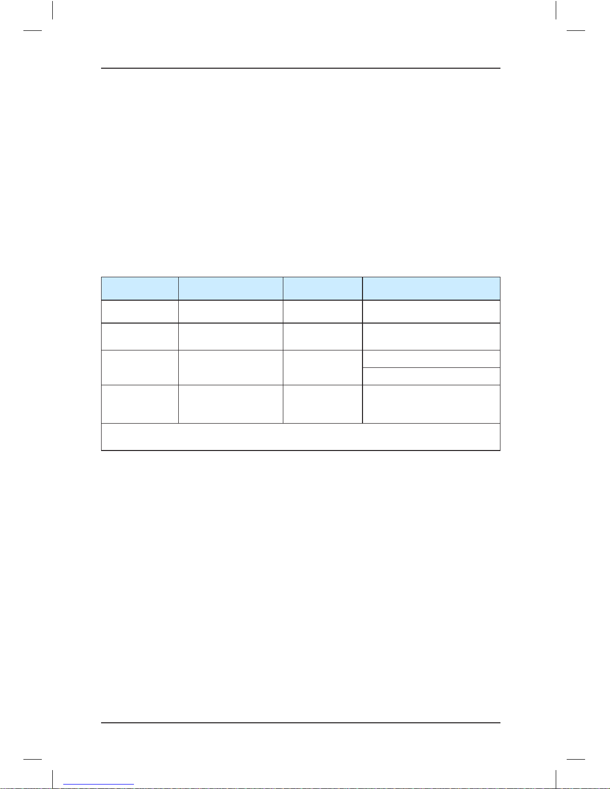
System Application Brief NICE3000 Instruction Manual
- 72 -
Chapter 6 System Application
6.1 Parallel Mode and Group Mode
6.1.1 Parameter Setting
The NICE3000 has the parallel control function. Two NICE3000 controllers can exchange
the elevator information by means of CAN or RS485 communication, coordinating response
of the two elevators to hall calls and improving the elevator efficiency.
The related parameters are set in the following table.
Table 6-1 Setting of the related parameters
Function Code Parameter Name Setting Range Setting in Parallel
F5-29 Y4 function selection 0–14 14
F6-07
Number of elevators
in group mode
1–8 2
F6-08 Elevator SN 1–8
Master elevator: 1
Slave elevator: 2
F6-09 Parallel selection
Bit2: Parallel
implemented at
monitoring port
Bit = 1 when CN5 is used for
the parallel mode
Note: The CAN communication port is used for the parallel mode by default. It is unnecessary
to set F6-09.
6.1.2 Setting of CTB Addresses
In parallel mode, the CTB address jumper of the master elevator (elevator whose SN is 1)
is the same as that used for the control of single elevator. That is, J2 is shorted in the ON
position. The CTB address jumper of the slave elevator (elevator whose SN is 2) is shorted
in the PARALLEL position. Otherwise, CTB data communication of the elevators becomes
abnormal.
For description of CTB terminals, see section 3.3. The following figure shows connection of
two elevators in parallel mode by means of CAN communication.
Page 74

Brief NICE3000 Instruction Manual System Application
- 73 -
Figure 6-1 Parallel connection by means of CAN communication
MCB
CN3
Elevator
1#
CN7
Y1M1Y2M2Y3M3Y4M4Y5M5Y6
M6
+24 V
COM
MOD+
MOD-
CAN+
CAN-
2
JP3
3
JP4
4
1
2
3
4
1
Full- load
indicator
HCB
LED
LED
2
JP1
3
JP2
4
1
2
3
4
1
CN1
2
JP3
3
JP4
4
1
2
3
4
1
Full-load
indicator
2
JP1
3
JP2
4
1
2
3
4
1
PRG UP SET
HCB
CAN communication port
connecting CTB of elevator 1#
CAN communication port
connecting CTB of elevator 2#
MCB
CN3
CN7
PRG UP SET
HCB of floor N HCB of floor N
UP button
DOWN button
CN1
Elevator
2#
+24 V
COM
MOD+
MOD-
CAN+
CAN-
Y1M1Y2M2Y3
M3
Y4M4M5M6Y5
Y6
6.1.3 Parallel Mode Using RS485 Communication (Monitoring Port)
When CAN communication is applied to parallel mode, if the 24 V power voltages of two
systems are different or the external interference is severe, the communication effect is
affected. To achieve better communication effect in parallel mode, we adopt RS485 at the
monitoring port of the MCB for communication of the parallel mode.
In t his cas e, the RS2 32 comm unica tion signal need s to be con verte d to RS48 5
communication signal. Thus, two optical-isolated RS232/RS485 converters (model: U485A)
are required. In field application, connect the RS232/RS485 converter to CN2 of the MCB,
and then correspondingly connect the two signal terminals (D+, D-) of the RS485 side of the
converter via a cable. Set F6-09 to Bit2 (Parallel implemented at monitoring port).
The following figure shows the parallel mode implemented at the monitoring port.
Page 75

System Application Brief NICE3000 Instruction Manual
- 74 -
Figure 6-2 Parallel connection at the monitoring port
6.1.4 Setting of Physical Floors
Physical floors, relative to the NICE3000 control system, are defined by the installation
position of the leveling flag. The floor (such as the ground floor) at which the lowest leveling
flag is installed corresponds to physical floor 1. The top physical floor is the accumulative
number of the leveling flags. In parallel mode, the physical floor numbers of the same floor
for two elevators are consistent.
If two elevators in parallel stop at different floors, physical floors should start with the lowest
leveling flag installation position. The physical floors at the overlapped area of the two
elevators are the same. Even if one elevator does not stop a floor in the overlapped area, a
leveling flag should be installed there. The user can make the elevator not stop at the floor
by setting service floors.
When two elevators are in parallel mode, the addresses of the HCBs should be set
according to physical floors. Parallel running can be implemented only when the HCB
addresses of one floor are set the same for the two elevators.
Note
In parallel mode, the top floor (F6-00) and bottom floor (F6-01) of the elevators should be set
based on corresponding physical floors.
Assume that there are two elevators in parallel. Elevator 1 stops at floor B1, floor 1, floor
2, and floor 3, while elevator 2 stops at floor 1, floor 3, and floor 4. Now, you need to set
related parameters and HCB addresses according to the following table.
Table 6-2 Parameter setting and HCB addresses of two elevators
Elevator 1 Elevator 2
Number of elevators
in group mode
2 2
Elevator SN 1 2
Actual
floor
Physical
floor
HCB
address
HCB display HCB address HCB display
Page 76

Brief NICE3000 Instruction Manual System Application
- 75 -
Elevator 1 Elevator 2
B1 1 1 FE-01 = 1101
1 2 2 FE-02 = 1901 2 FE-02 = 1901
2 3 3 FE-03 = 1902
Bypass floor but
leveling flag required
FE-03=1902
3 4 4 FE-04 = 1903 4 FE-04=1903
4 5 5 FE-05=1904
Bottom floor
(F6-01)
1 2
Top floor (F6-00) 4 5
Service floor (F6-05) 65535
65531 (It does not stop at physical
floor 3)
6.1.5 Group Mode
The group control board is required if three or more elevators work in group mode. For
details, see the Monarch's Use Instruction of Group Control Board.
6.2 Emergency Evacuation at Power Failure
Passengers may be trapped in the car if power failure suddenly happens during the use of
the elevator. The evacuation function at power failure is designed to solve the problem.
The evacuation function is implemented in the following two modes:
• Uninterrupted power supply (UPS)
• Shorting PMSM stator
Here we first introduce the implementation through the NICE3000's shorting PMSM stator
scheme, which can save energy and improve safety.
6.2.1 Shorting PMSM Stator
Shorting PMSM stator means shorting phases UVW of the PMSM, which produces
resistance to restrict movement of the elevator car. In field application, an auxiliary NC
contact is usually added to the NO contact of the output contactor to short PMSM UVW
to achieve the effect. It is feasible in theory but may cause over-current actually. Due to
the poor quality of the contactor and the wiring of adding the auxiliary contact, the residual
current of the controller is still high when the outputs UVW are shorted at abnormal stop.
This results in an over-current fault and may damage the controller or motor.
Monarch's shorting PMSM stator scheme requires the installation of an independent
contactor for shorting PMSM stator. The shorting PMSM stator function is implemented via
the relay NC contact. On the coil circuit of the RUN contactor, an NO contact of the shorting
PMSM stator contactor is connected in serial to ensure that output short-circuit does not
occur when the parameter setting is incorrect.
The following figure shows wiring of the independent shorting PMSM stator contactor.
Page 77

System Application Brief NICE3000 Instruction Manual
- 76 -
Figure 6-3 Wiring of the independent shorting PMSM stator contactor
Y1
M1
101
102
U
V
W
NIC E3000
M
SW: RUN contactor
SW
Motor
U
V
W
1 2
3
4
5
6
Y3
M3
101
102
FX: s horting PMSM
stator contactor
FX
Safety circuit
110 VAC
1 2
3 4
5 6
FX
24 VX18
Then set the related parameters as follows:
Table 6-3 Parameter setting under the shorting PMSM stator scheme
Function Code Parameter Name Setting Value Description
F5-18
X18 function
selection
30
Allocate X18 with "NO input of
shorting PMSM stator feedback".
F5-28 Y3 function selection 12
Allocate Y3 with "Shorting PMSM
stator contactor feedback".
FE-33
Bit6 1
Enable the shorting PMSM stator
function.
Bit8 1
Set the shorting PMSM stator
contactor to NC mode.
6.2.2 Emergency 220 V UPS
In this scheme, the 220 V UPS provides power supply to the main unit and the drive control
circuit. The following figure shows the emergency 220 V UPS circuit.
Figure 6-4 Emergency 220 V UPS circuit
220 VAC
115 VAC
UPS-220V
UPC
Safety
contactor
21 22
Y6
M6
MCB
61 62
21 22
2
1
3 4
R
N
Transformer
115 VDC
220 VAC
UPS-0V
(6 A)
(6 A)
UPC
A1
A2
65
14
13
UPC
S
T
R
NICE3000
Page 78

Brief NICE3000 Instruction Manual System Application
- 77 -
The following figure shows various contacts of the contactors.
Figure 6-5 Various contacts of the contactors
0 V
Safety
contactor
A1 A2
53 54
11 14
Phase
sequence relay
Safety circuit
UPC
UPC
71 72
21 22
UPC
X2024 V
Emergency
feedback
UPC
214
3
6
5
13
14
22
215453
61
62 72
71 81
82
110 V
The UPS power is recommended in the following table.
Table 6-4 Recommended UPS power for each power rating
UPS Power Controller Power
1 kVA (700–800 W) ≤ 5.5 kW
2 kVA (1400–1600 W) > 5.5 kW and ≤ 11 kW
3 kVA (2100–2400 W) 15 kW
The following table lists the setting of the related parameters.
Table 6-5 Parameter setting under the 220 V UPS scheme
Function Code Parameter Name Setting Value Description
F8-09
Emergency
evacuation operation
speed at power failure
0.05 m/s
Set the running speed for
emergency evacuation
operation.
F8-10
Emergency
evacuation operation
mode at power failure
0: Motor not
running
1: UPS
2: 48 V battery
power supply
Set the emergency
evacuation operation mode.
F5-20 (X20) X20 function selection 59
Allocate X20 with "NC input
of UPS valid signal".
F5-31 (Y6) Y6 function selection 13
Allocate Y6 with
"Emergency evacuation
operation".
Note
UPS emergency output at power failure can be allocated only to Y6.
Page 79

System Application Brief NICE3000 Instruction Manual
- 78 -
6.3 Opposite Door Control
Set related parameters according to the following table.
Table 6-6 Parameter setting for opposite door control
Opposite Door
Control Mode
Parameter Setting Function Description
0
(simultaneous
control)
FE-33 BIT15 = 0:
disable opposite
door independent
control
The hall call buttons of both door sides are connected
in parallel to implement simultaneous control on the
opposite door. A maximum of 40 floors are supported.
FE-33 BIT15 =
1: opposite door
independent control
FC-04=0:
simultaneous
control
The hall call DIP switch address of the front door is
set based on floor (1-15). The hall call DIP switch
address of the back door is set based on floor +16
(17-31).
A maximum of 15 floors are supported. The
front door and back door are opened and closed
simultaneously.
1 (hall call
independent,
car call
simultaneous)
FE-33 BIT15 =
1: opposite-door
independent control
FC-04 = 1: hall call
independent, car
call simultaneous
The hall call DIP switch address of the front door is
set based on floor (1-15). The hall call DIP switch
address of the back door is set based on floor +16
(17-31). A maximum of 15 floors are supported.
In this control mode, hall call is independent. Front
door opens upon arriving at the floor with front door
hall call. Back door opens upon arriving at the floor
with back door hall call. Both doors open if the two
doors have hall call respectively.
When arriving at the floor with car call, the elevator
opens both doors.
2 (hall call
independent,
oppositedoor manual
control)
FE-33 BIT15 =
1: opposite-door
independent control
FC-04 = 2: Hall
call independent,
opposite-door
manual control
The hall call DIP switch address of the front door is
set based on floor (1-15). The hall call DIP switch
address of the back door is set based on floor +16
(17-31). A maximum of 15 floors are supported. JP16
is the door switchover switch.
In this control mode, hall call is independent. Front
door opens upon arriving at the floor with front door
hall call. Back door opens upon arriving at the floor
with back door hall cal. Both doors open if the two
doors have hall call respectively.
The front door and back door are controlled by JP16
for arriving at the floor with car call.
Page 80

Brief NICE3000 Instruction Manual System Application
- 79 -
Opposite Door
Control Mode
Parameter Setting Function Description
3 (hall call
independent,
car call
independent)
FE-33 BIT15 =
1: opposite-door
independent control
FC-04 = 3: hall call
independent, car
call independent
This control mode applies to double call boards,
double operation panels and two CCBs connected
in serial. The hall call DIP switch address of the front
door is set based on floor (1-15). The hall call DIP
switch address of the back door is set based on floor
+16 (17-31).
The car calls of the front door are controlled by JP1
to JP15 of CCB1, and the car calls of the back door
are controlled by JP1 to JP15 of CCB2. JP16 of
CCB1 is the back-door open button, and JP17 of
CCB1 is the front-door open button. JP18 of CCB1 is
the common door close button
A maximum of 15 floors are supported, with
independent control on hall calls and car calls. CCB2
is the next-level call board of CCB1.
Note
In the fire emergency, inspection or re-eveling state, the opposite door is under simultaneous
control rather than independent control.
Page 81

Page 82

7
Troubleshooting
Page 83

Troubleshooting Brief NICE3000 Instruction Manual
- 82 -
Chapter 7 Troubleshooting
7.1 Description of Fault Levels
The NICE3000 has more than 60 pieces of alarm information and protective functions. It
monitors various input signals, running conditions and feedback signals. If a fault occurs, the
relevant protective function acts and the system displays the fault code.
The controller is a complicated electronic control system and the displayed fault information
is graded into 5 levels according to the severity. The faults of different levels are handled
according to the following table.
Table 7-1 Fault levels
Category Action Remarks
Level 1
Display fault code.
Output fault relay action command.
The elevator running
is not affected on any
condition.
Level 2
Display fault code.
Output fault relay action command.
Disable the elevator group control (parallel control)
mode.
The elevator can run
properly.
Level 3
Display fault code.
Output fault relay action command.
Make the elevator stop at the nearest landing floor,
and then forbid running in distance control.
Make the elevator stop immediately in other conditions.
The controller
immediately stops
output and applies the
brake after stop.
Level 4
Display fault code.
Output fault relay action command.
In distance control, the controller stops output and
applies the brake immediately after stop. Low- speed
running (such as re- leveling and inspection) is
allowed.
The elevator can run
at low speed with fault
code.
Level 5
Display fault code.
Output fault relay action command.
The controller stops output and applies the brake
immediately, and then forbids running.
The controller forbids
running.
Note
• Low-speed running involves inspection, emergency rescue, shaft auto-tuning, re-leveling, motor
auto-tuning, base floor detection, and running in operation panel control.
• Normal-speed running involves automatic running, returning to base floor in fire emergency
state, firefighter operation, attendant operation, elevator locked, and elevator parking.
Page 84

Brief NICE3000 Instruction Manual Troubleshooting
- 83 -
7.2 Fault Information and Troubleshooting
If an alarm is reported, the system performs corresponding processing based on the fault
level. You can handle the fault according to the possible causes described in the following
table.
Table 7-2 Fault codes and troubleshooting
Fault
Code
Name Possible Causes Solution Level
E01
Invert unit
protection
1. The main circuit
output is grounded or
short circuited.
2. The connecting
cable of the motor is
too long.
3. The working
temperature is too
high.
4. The internal
connections become
loose.
1. Eliminate external faults.
2. Install a reactor or an output
filter.
3. Check the air channel and
the cooling fan.
4. Contact the agent or
Monarch.
5
E02
Over-current
during
acceleration
1. The main circuit
output is grounded or
short circuited.
2. Motor autotuning is performed
improperly.
3. The load is too
heavy.
4. The encoder signal
is incorrect.
5. The UPS running
feedback signal is
abnormal.
1. Check whether the RUN
contactor at the controller
output side is normal.
2. Check whether the power
cable jacket is damaged,
whether the power cable is
possibly short circuited to
ground and whether the cable
is connected reliably.
3. Check the insulation of motor
power terminals, and check
whether the motor winding is
short-circuited or grounded.
4. Check whether the shorting
PMSM stator contactor causes
controller output short circuit.
5. Check whether motor
parameters comply with the
nameplate.
6. Perform motor auto-tuning
again.
7. Check whether the brake
keeps released before the fault
occurs and whether the brake is
stuck mechanically.
(To be continued)
5
E03
Over-current
during
deceleration
1. The main circuit
output is grounded or
short circuited.
2. Motor autotuning is performed
improperly.
3. The load is too
heavy.
4. The deceleration
rate is too short.
5. The encoder is
seriously interfered
with.
5
Page 85

Troubleshooting Brief NICE3000 Instruction Manual
- 84 -
Fault
Code
Name Possible Causes Solution Level
E04
Over-current at
constant speed
1. The main circuit
output is grounded or
short circuited.
2. Motor autotuning is performed
properly.
3. The load is too
heavy.
4. The encoder is
seriously interfered
with.
8. Check whether the balance
coefficient is correct.
9. Check whether the encoder
wirings are correct. For
asynchronous motor, perform
SFVC and compare the current
to judge whether the encoder
works properly.
10. Check whether the encoder
lines per revolution is set
correctly, whether the encoder
signal is interfered with,
whether the encoder cable runs
through the duct independently,
whether the cable is too long
and whether the shielding layer
is grounded at one end.
11. Check whether the encoder
is installed reliably, whether
the rotating shaft is connected
to the motor shaft reliably and
whether the encoder is stable
during normal-speed running.
12. Check whether UPS
feedback is valid in the nonUPS running state E02).
13. Check whether the
acceleration/deceleration rate is
too high.
5
E05
Over-voltage
during
acceleration
1. The input voltage
is too high.
2. The regeneration
power of the motor is
too high.
3. The braking
resistance is too
large, or the braking
unit fails.
4 .The acceleration
rate is too short.
1. Adjust the input voltage.
Observe whether the bus
voltage is normal and whether it
rises too quickly during running.
2. Check for the balance
coefficient.
3. Select a proper braking
resistor and check whether the
resistance is too large based
on the recommended braking
resistance table in chapter 3.
(To be continued)
5
Page 86

Brief NICE3000 Instruction Manual Troubleshooting
- 85 -
Fault
Code
Name Possible Causes Solution Level
E06
Over-voltage
during
deceleration
1. The input voltage
is too high.
2. The braking
resistance is too
large, or the braking
unit fails.
3. The deceleration
rate is too short.
4. Check whether the cable
connecting the braking resistor
is damaged, whether the
cooper wire touches the ground
and whether the connection is
reliable.
5
E07
Over-voltage at
constant speed
1. The input voltage
is too high.
2. The braking
resistance is too
large, or the braking
unit fails.
5
E09 Under-voltage
1. Instantaneous
power failure occurs
on the input power
supply.
2. The input voltage
is too low.
3. The drive control
board fails.
1. Eliminate external power
supply faults and check whether
the power fails during running.
2. Check whether the wiring
of all power input cables is
reliable.
3. Contact the agent or
Monarch.
5
E10
Controller
overload
1. The brake circuit is
abnormal.
2. The load is too
heavy.
3. The encoder
feedback signal is
abnormal.
4. The motor
parameters are
incorrect.
5. A fault occurs on
the motor power
cables.
1. Check the brake circuit and
power input.
2. Reduce the load.
3. Check whether the encoder
feedback signal and setting are
correct. Check whether initial
angle of the encoder for the
PMSM is correct.
4. Check the motor parameter
setting and perform motor autotuning.
5. Check the power cables of
the motor (refer to the solution
of E02).
4
E11 Motor overload
1. FC-02 is set
improperly.
2. The brake circuit is
abnormal.
3. The load is too
heavy.
1. Adjust the parameter (FC-02
can be set to the default value).
2. Refer to E10.
3
E12
Power supply
phase loss
1. The power input is
not symmetric.
2. The drive control
board fails.
1. Check whether the three
phases of power supply are
balanced and whether the
power voltage is normal. If not,
adjust the power input.
2. Contact the agent or
Monarch.
4
Page 87

Troubleshooting Brief NICE3000 Instruction Manual
- 86 -
Fault
Code
Name Possible Causes Solution Level
E13
Power output
phase loss
1. The output wiring
of the main circuit is
loose.
2. The motor is
damaged.
1. Check the wiring.
2. Check whether the contactor
at the output side is normal.
3. Eliminate the motor fault.
4
E14
Module
overheat
1. The ambient
temperature is too
high.
2. The fan is
damaged.
3. The air channel is
blocked.
1. Lower the ambient
temperature.
2. Clear the air channel.
3. Replace the damaged fan.
4. Check whether the
installation clearance of
the controller satisfies the
requirement in chapter 3.
5
E16 Encoder fault
1. The startup
position is incorrect.
2. The torque
deviation is too large.
3. The speed
deviation is too large.
1. Check the encoder circuit.
2. Turn off the output MCCB.
3. The current loop parameters
are too small.
4. The zero-point position is
incorrect. Perform motor autotuning again.
5. Reduce the load
5
E17
Encoder signal
check abnormal
The deviation of
real-time angle and
reference angle of
the 1387 encoder is
too large.
1. Check whether the encoder
is normal.
2. Check whether the encoder
wiring is reliable and normal.
3. Check whether the PG card
wiring is proper.
4. Check whether the main
unit and control cabinet are
grounded well.
5
E18
Current
detection fault
The drive control
board fails.
Contact the agent or Monarch.
E19
Motor autotuning fault
1. The motor cannot
rotate properly.
2. The motor autotuning times out.
3. The encoder for
the PMSM fails.
1. Enter the motor parameters
correctly.
2. Check the motor wiring and
whether phase loss occurs on
the contactor at the output side.
3. Check the feedback encoder
wiring and ensure that PPR of
the encoder is set properly.
4. Check whether the brake
keeps released during no-load
auto-tuning.
5. Check whether the inspection
button is released before the
PMSM with-load auto-tuning is
finished.
5
Page 88

Brief NICE3000 Instruction Manual Troubleshooting
- 87 -
Fault
Code
Name Possible Causes Solution Level
E20 Encoder fault
1. Check whether
the encoder model
matches the motor.
2. The encoder wiring
is incorrect.
3. The current keeps
large during lowspeed running.
1. Check whether F1-00 is set
correctly.
2. Check the encoder wiring.
3. Check whether the encoder
is normal.
4. Check whether the encoder
is stuck mechanically during
running.
5. Check whether the brake
keeps released during running.
5
E22
Leveling signal
abnormal
Leveling or door
zone signal is stuck
or breaks.
1. Check whether the leveling
and door zone sensors work
properly.
2. Check the installation
verticality and depth of the
leveling flags.
3. Check the input points of the
MCB.
1
E23
Short circuit to
ground
The output is short
circuited to ground.
Check the power cable or
contact Monarch.
5
E25
EEPROM
failure
EEPROM of the MCB
fails.
Contact the agent or Monarch. 5
E29
Shorting PMSM
stator feedback
abnormal
The shorting PMSM
stator's output is
inconsistent with the
feedback.
1. Check whether the feedback
contact (NO, NC) of the
contactor is consistent with the
parameter setting of the MCB.
2. Check whether the state of
the MCB output indicator is
consistent with the contactor
action.
3. Check whether
corresponding feedback contact
acts after the contactor acts,
and whether the corresponding
feedback input point of the MCB
acts correctly.
4. Check whether the shorting
PMSM stator contactor is
consistent with the MCB output
feature.
5. Check the coil circuit of the
shorting PMSM stator contactor.
5
Page 89

Troubleshooting Brief NICE3000 Instruction Manual
- 88 -
Fault
Code
Name Possible Causes Solution Level
E30
Elevator
position
abnormal
1. The controller does
not receive leveling
signal within the time
set in F9-02.
2. The up and down
limit switches are met
during the re-leveling
process.
3. The leveling signal
is not received when
re-leveling times out.
1. Check whether the leveling
sensor mal-acts in non-leveling
zone.
2. Check whether the leveling
signal cables are connected
reliably and whether the signal
copper wires may touch the
ground or be short circuited with
other signal cables.
3. Check whether the encoder
is used properly.
4
E31
DPRAM
abnormal
DPRAM reading and
writing are abnormal
Contact the agent or Monarch
to replace the control board.
3
E32 CPU abnormal
The CPU is
abnormal.
1. Check jumpers J9 and J10
and check whether only the
right two pins of J9 are shorted.
2. Contact the agent or Monarch
to replace the control board.
5
E33
Elevator speed
abnormal
1. The feedback
speed is 1.15 times
of the maximum
running speed.
2. The speed is
higher than 0.65 m/
s in the inspection
state.
3. The speed
exceeds half of the
rated speed during
emergency running.
1. Check whether the encoder
is used properly.
2. Check the setting of motor
nameplate parameters.
3. Perform motor auto-tuning
again.
4. Check inspection switch and
signal cables.
5
E34 Logic fault
Redundancy
judgment and logic of
the control board are
abnormal.
Contact the agent or Monarch
to replace the control board.
5
Page 90

Brief NICE3000 Instruction Manual Troubleshooting
- 89 -
Fault
Code
Name Possible Causes Solution Level
E35
Shaft autotuning data
abnormal
1. The elevator is not
at the bottom floor
when shaft autotuning is started.
2. No leveling signal
is received within
45s while continuous
running.
3. The distance
between two floors is
too small.
4. The maximum
number of landing
floors is inconsistent
with the setting value.
5. The floor pulses
change inversely.
6. The system is not
in the inspection state
when shaft autotuning is performed.
7. Shaft auto-tuning
is not performed
upon power-on.
1. Upon power-on, E35 is
reported when the flag height
is detected to be 0 or the RUN
contactor is detected to keep
open.
• Check whether the down
slow-down switch is valid.
• Check whether the current
floor (F4-01) is set to 1, and
whether F0-00 is set to 1.
• Check whether the inspection
switch is set to the inspection
state.
2. E35 is reported when the first
leveling position is reached.
• Check whether F4-03
increases when the elevator
runs up. If not, adjust F2-10.
• Check whether the NC/NO
setting of the leveling sensor
is correct.
• If the leveling sensor signal
blinks, check whether the
flag is installed properly.
3. E35 is reported during
running.
• Check whether the running
times out: no leveling signal
is received when the running
time exceeds F9-02.
• Check whether the super
short floor function is enabled
when the floor distance is
less than 50 cm.
• Check whether the setting
of F6-00 (Top floor of the
elevator) is smaller than the
actual condition.
4. E35 is repo rt ed when the
elevator arrives at the top floor.
• Check whether the obtained
top floor of the elevator and
bottom floor of the elevator
are consistent with the setting
of F6-00 and F6-01 when the
up slow-down signal is valid
and the elevator reaches the
door zone.
• Check whether the obtained
floor interval is less than 50
cm.
4
Page 91

Troubleshooting Brief NICE3000 Instruction Manual
- 90 -
Fault
Code
Name Possible Causes Solution Level
E36
RUN contactor
feedback
abnormal
1. The RUN contactor
feedback is valid
when the elevator
starts up.
2. The feedback
signal is not received
2s after the output of
the RUN contactor.
3. The running
current of the
elevator is less than
0.1 A after the output
of both the RUN
contactor and the
brake contactor.
1. Check whether the feedback
contact of the contactor acts
properly.
2. Check whether the feedback
contact (NO, NC) of the
contactor is consistent with the
MCB parameter setting.
3. Check whether the output
cables UVW of the controller
are connected properly.
4. Check whether the power
supply of the controller's control
circuit is normal.
5
E37
Brake contactor
feedback
abnormal
The output of the
brake contactor is
inconsistent with the
feedback.
1. Check whether the brake
coil and feedback contact are
correct.
2. Confirm the signal feature
(NO, NC) of the feedback
contact.
3. Check whether the power
supply of the brake coil's control
circuit is normal.
5
E38
Encoder signal
abnormal
1. There is no input
of the encoder pulses
when the elevator
runs automatically.
2. The direction of
the input encoder
signal is incorrect
when the elevator
runs automatically.
3. F0-00 is set to 0
(SFVC) in distance
control.
1. Check whether the encoder
is used correctly.
2. Exchange phases A and B of
the encoder.
3. Check the setting of F0-00,
and change it to "CLVC".
4. Check whether the system
and signal cables are grounded
reliably.
5. Check whether cabling
between the encoder and the
PG card is normal.
5
E39 Motor overheat
Motor overheat input
is valid.
1. Check whether the motor is
used properly and whether it is
damaged.
2. Improve cooling conditions of
the motor.
3
E40
Elevator running
time-out
The setting of the
elevator running time
is exceeded.
The elevator is used for a long
time and needs maintenance.
4
Page 92

Brief NICE3000 Instruction Manual Troubleshooting
- 91 -
Fault
Code
Name Possible Causes Solution Level
E41
Safety circuit
breaking
The safety circuit
signal breaks off.
1. Check the status of the
safety circuit switches.
2. Check whether the external
power supply is normal.
3. Check whether the safety
circuit contactor acts properly.
4. Confirm the signal feature
(NO, NC) of the feedback
contact of the safety circuit
contactor.
5
E42
Door lock
breaking off
during running
The door lock circuit
feedback breaks off
during the elevator
running.
1. Check whether the landing
door lock and the car door lock
are in good contact.
2. Check whether the door lock
contactor acts properly.
3. Confirm the signal feature
(NO, NC) of the feedback
contact on the door lock
contactor.
4. Check whether the external
power supply is normal.
5
E43
Up limit signal
breaking off
during running
The up limit signal
breaks off when the
elevator is running
up.
1. Confirm the feature (NO, NC)
of the up limit signal and down
limit signal.
2. Check whether the up limit
and down limit switches act
properly.
3. The installation positions
of limit switches are too close
to the leveling flag. The limit
switches will be touched at
normal leveling.
4
E44
Down limit
signal breaking
off during
running
The down limit signal
breaks off when the
elevator is running
down.
4
E45
Slow-down
switch position
abnormal
1. The installation
positions of the slowdown switches do not
satisfy the slow-down
requirements.
2. The recorded
slow-down switch
position is greatly
different from the
actual position.
1. Ensure that the installation
positions satisfy the
requirements.
2. Check whether the slowdown switches act properly.
3. Set the NC/NO state of slowdown signal correctly.
4
Page 93

Troubleshooting Brief NICE3000 Instruction Manual
- 92 -
Fault
Code
Name Possible Causes Solution Level
E46
Re-leveling
abnormal
1. The re-leveling
running speed
exceeds 0.1 m/s.
2. The elevator is
out of the door zone
when re-leveling.
3. The feedback of
the shorting door lock
circuit contactor is
abnormal.
1. Check the original and
secondary wiring of the shorting
door lock circuit relay.
2. Check whether the shorting
door lock circuit contactor
feedback function is enabled
and whether the feedback
signal is normal.
3. Check whether the encoder
is used properly.
1
E47
Shorting door
lock circuit
contactor failure
1. The feedback of
the shorting door lock
circuit fails.
2. The elevator runs
at over speed or the
running times out
when the shorting
door lock circuit
contactor has output.
1. Confirm the signal feature
(NO, NC) of the feedback
contact on the shorting door
lock circuit contactor.
2. Check whether the shorting
door lock circuit contactor acts
properly.
1
E48 Door open fault
The consecutive
times that the door
does not open/close
to the limit reaches
the setting in FB-09.
1. Check whether the door
machine system works properly.
2. Check whether the CTB is
normal.
5
E49 Door close fault
E51
CAN
communication
abnormal
Feedback from the
CTB is abnormal.
1. Check the communication
cable connection.
2. Check whether the 24 V
power supply of the NICE3000
is normal.
1
E52
HCB
communication
abnormal
Feedback from the
HCB is abnormal.
1. Check the communication
cable connection.
2. Check whether the 24 V
power supply of the NICE3000
is normal.
3. Check whether the HCB
addresses are repeated.
1
E53
Shorting door
lock circuit fault
1. The door lock
and door open limit
signals are valid
simultaneously.
2. The landing door
lock and the hall door
lock are in different
states.
1. Check whether the door lock
circuit is normal.
2. Check whether the feedback
contact of the door lock
contactor acts properly.
3. Check whether the system
receives the door open limit
signal when the door lock signal
is valid.
5
E54
Over-current
at startup of
inspection
running
The current exceeds
110% of the rated
current at the startup
of inspection running.
1. Reduce the load.
2. Perform the motor autotuning again.
5
Page 94

Brief NICE3000 Instruction Manual Troubleshooting
- 93 -
Fault
Code
Name Possible Causes Solution Level
E55
Stop at another
landing floor
The door does not
open to the limit
at the current floor
when the elevator
runs automatically.
Check the door open limit
signal.
1
E57
DSP
communication
abnormal
The time during
which DSP and
MCB have no
communication
reaches 500 ms.
1. Check the connection
between the control board and
the drive board.
2. Replace the controller.
5
Page 95

Troubleshooting Brief NICE3000 Instruction Manual
- 94 -
Page 96

Warranty Agreement
1) The warranty period of the product is 18 months (refer to the barcode on the
equipment). During the warranty period, if the product fails or is damaged under the
condition of normal use by following the instructions, Monarch will be responsible for
free maintenance.
2) Within the warranty period, maintenance will be charged for the damages caused by
the following reasons:
A. Improper use or repair/modification without prior permission
B. Fire, flood, abnormal voltage, other disasters and secondary disasters
C. Hardware damage caused by dropping or transportation after procurement
D. Improper operations
E. Damage out of the equipment (for example, external device factors)
3) If there is any failure or damage to the product, please correctly fill out the Product
Warranty Card in detail.
4) The maintenance fee is charged according to the latest Maintenance Price List of
Monarch.
5) The Product Warranty Card is not re-issued. Please keep the card and present it to the
maintenance personnel when asking for maintenance.
6) If there is any problem during the service, contact Monarch's agent or Monarch directly.
7) This agreement shall be interpreted by Suzhou MONARCH Control Technology Co.,
Ltd.
Service Department, Suzhou MONARCH Control Technology Co., Ltd.
Address: 16, Youciang Rd, Wangshan Industrial Park, Wuzhong Economic Development
Zone, Suzhou, China
Service Hotline: (+86) 400-777-1260 P.C.: 215104
Website: www.SZMCTC.cn
Page 97
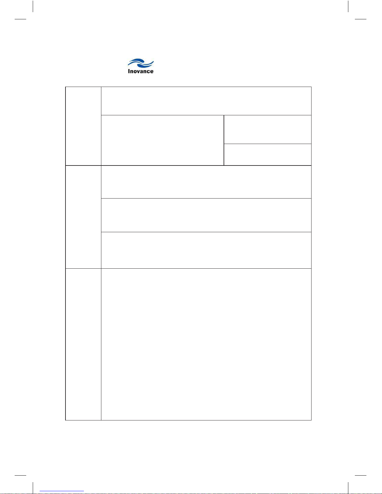
Product Warranty Card
Customer
information
Add. of unit:
Name of unit:
P.C.:
Contact person:
Tel.:
Product
information
Product model:
Body barcode (Attach here):
Name of agent:
Failure
information
(Maintenance time and content):
Maintenance personnel:
Page 98

 Loading...