

Page 1
Data code:19010227
Integrated Elevator Controller
User Manual V0.0
new
NICE1000
new
NICE1000
Integrated Elevator Controller
Page 2

NICE1000
new
User Manual Preface
- 1 -
Preface
Thank you for purchasing the NICE1000
new
integrated elevator controller.
The NICE1000
new
is a new-generation integrated elevator controller independently
developed and manufacturered by Suzhou MONARCH Control Technology Co., Ltd., by
optimizing the NICE1000 controller based on a large number of applications and combining
new industrial features.
The NICE1000
new
has the following advantages:
1. It supports high-performance vector control and open-loop low speed running. It can
drive both AC asynchronous motor and permanent magnetic synchronous motor
(PMSM), and implement switchover between the two types of motors easily by modifying
only one parameter.
2. It supports open-loop low-speed running, direct parallel control of two elevators, and
CANbus and Modbus communication protocols for remote monitoring.
3. It supports a maximum of 16 oors and is widely applied to elevators used in the villa
and freight elevators.
This manual describes the correct use of the NICE1000
new
, including product features,
safety information and precautions, installation, parameter setting, commissioning, and
maintenance & inspection. Read and understand the manual before using the product, and
keep it carefully for reference to future maintenance.
The personnel who involve in system installation, commissioning, and maintenance must
receive necessary safety and use training, understand this manual thoroughly, and have
related experience before performing operations.
Notes
•The drawings in the manual are sometimes shown without covers or protective guards.
Remember to install the covers or protective guards as specied rst, and then perform
operations in accordance with the instructions.
•The drawings in the manual are shown for description only and may not match the product
you purchased.
•The instructions are subject to change, without notice, due to product upgrade, specication
modication as well as efforts to increase the accuracy and convenience of the manual.
•Contact our agents or customer service center if you need a new user manual or have
problems during the use.
•Email: UM@inovance.cn
Page 3
Introduction NICE1000
new
User Manual
- 2 -
■Product Checking
Upon unpacking, check:
•Whether the nameplate model and controller ratings are consistent with your order. The
box contains the controller, certicate of conformity, user manual and warranty card.
•Whether the controller is damaged during transportation. If you find any omission or
damage, contact your supplier or Monarch immediately.
■First-time Use
For users who use this product for the rst time, read the manual carefully. If you have any
problem concerning the functions or performance, contact the technical support personnel
of Monarch to ensure correct use.
■CE Mark
The CE mark on the NICE1000
new
declares that the controller complies with the European
low voltage directive (LVD) and EMC directive.
■Standard Compliance
The NICE1000
new
series controller complies with the following LVD and EMC directives and
standards:
Directive Directive Code Standard
EMC Directive 2004/18/EC
EN 61800-3: 2004+A1: 2012
EN 12015: 2004
EN 12016: 2004+A1: 2008
LVD Directive 2006/95/EC EN 61800-5-1
The NICE1000
new
series controller complies with the requirements of the EMC standard on
the condition of correct installation and use by following the instructions in chapter 9 "EMC".
Page 4
NICE1000
new
User Manual Introduction
- 3 -
Introduction
1. Comparison with the NICE1000
The following table lists the comparison between the NICE1000
new
and the NICE1000.
Item NICE1000 NICE1000
new
Maximum number of oors
Standard: 6
(can be extended to 8)
Standard: 8
(can be extended to 16)
Maximum elevator speed 1 m/s 1.75 m/s
I/O terminals
•Digital input: 24
•Button input and indicator
output: standard 20 (can be
extended to 26)
•Relay output: standard 21
(can be extended to 24)
•Higher-voltage input: 3
•Digital input: 24
•Button input and indicator
output: standard 26 (can
be extended to 50)
•Relay output: standard 21
(can be extended to 27)
•Higher-voltage input: 3
CANbus None 1 x CANbus
Modbus None 1 x Modbus
Motor driving type
Separate control for
synchronous and
asynchronous motors
Integrated control
for synchronous and
asynchronous motors
No-load-cell startup
Supporting SIN/COS encoder
only
Supporting:
•Push-pull encoder
•Open-collector incremental
encoder
•UVW encoder
•SIN/COS encoder
•Endat encoder
Control mode
•Sensorless vector control
(SVC)
•Closed-loop vector control
(CLVC)
•Sensorless vector control
(SVC)
•Closed-loop vector control
(CLVC)
•V/F control
Commissioning via Android
cell phone (not providing
English version currently)
Not support Support
PG card for asynchronous
motor
Not requiring PG card Requiring MCTC-PG-A2
Extension card MCTC-KZ-B MCTC-KZ-D
Use of optional part
The PG card and the
extension card use the same
interface on the MCB, and
they cannot be used at the
same time.
The PG card and the
extension card can be used
at the same time.
Page 5
Introduction NICE1000
new
User Manual
- 4 -
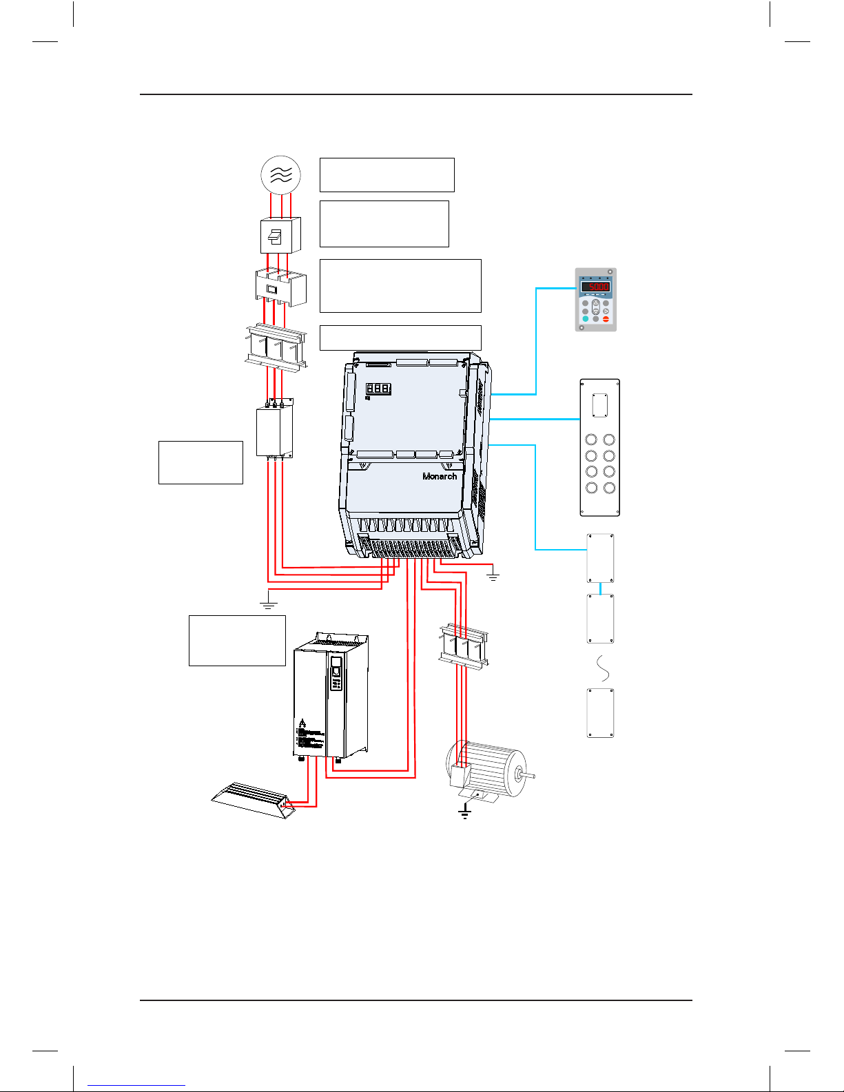
2. Connection to peripheral devices
Ground
AC input reactor
Electromagnetic
contactor
Molded case circuit
breaker (MCCB) or
earth leakage circuit
breaker (ELCB)
Three-phase AC
power supply
Braking resistor
Noise filter on
input side
To guarantee safety, use an
electromagnetic contactor. Do not
use it to start or stop the controller
because such operation reduces
the service life of the controller.
Select a proper breaker to
resist large in-rush current
that flows into the controller
at power-on.
Use within the allowable
power supply specification of
the controller.
Reliably ground the
motor and the
controller to prevent
electric shock.
Reduce the
electromagnetic
interference on
the input side.
P(+)
BR
Braking
unit
+
-
Motor
MF.K
RUN
STOP
RES
QUICK
PRG ENTER
RUN
LOCAL/REMOT FED/REV TUNE/TC
RPM
%
A VHz
External operation panel
Output
reactor
Ground
Ground
Operation box
Hall display
board
Bottom floor
Top floor
Hall display
board
2
4
5
7
8
6
3
1
Suppress the high order harmonic
to improve the power factor.
NICE1000
new
integrated elevator
controller
•For model selection of the peripheral electrical devices, refer to section 3.4.
•The NICE1000
new
in the preceding figure is the standard model. For information about
other structures, refer to section 2.5.
Page 6
NICE1000
new
User Manual Introduction
- 5 -
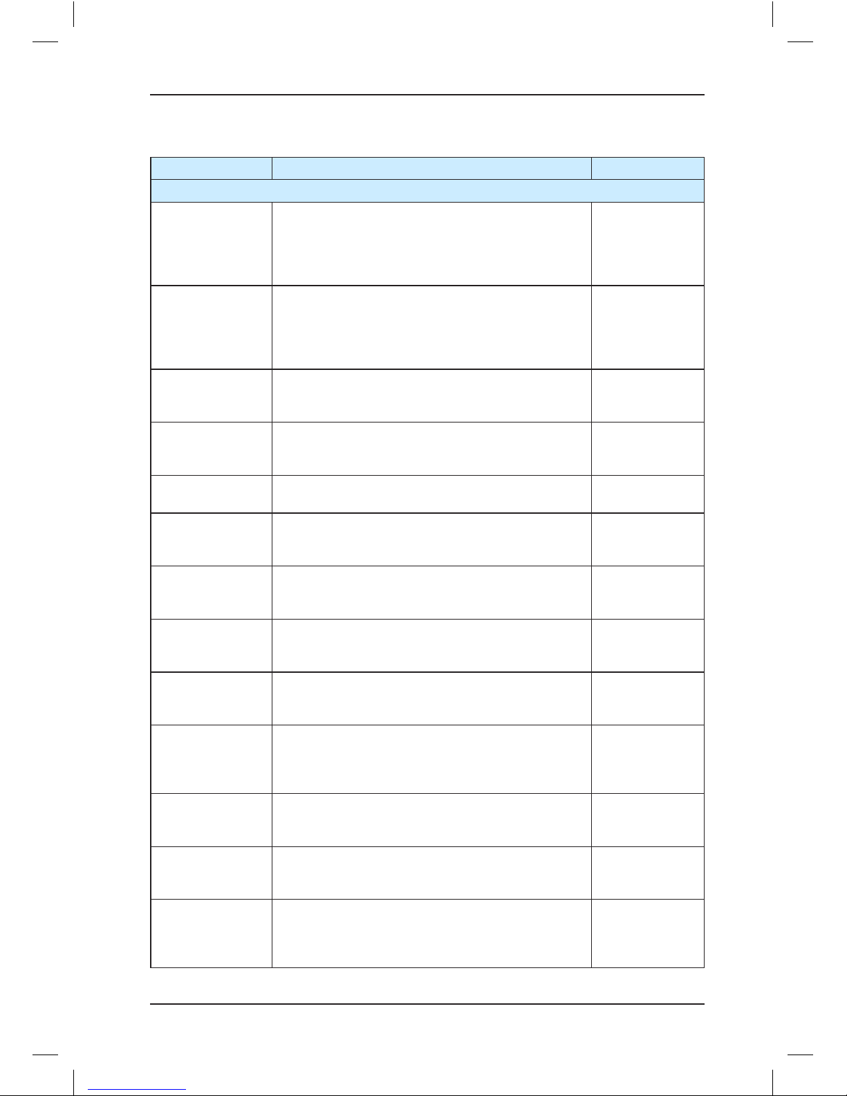
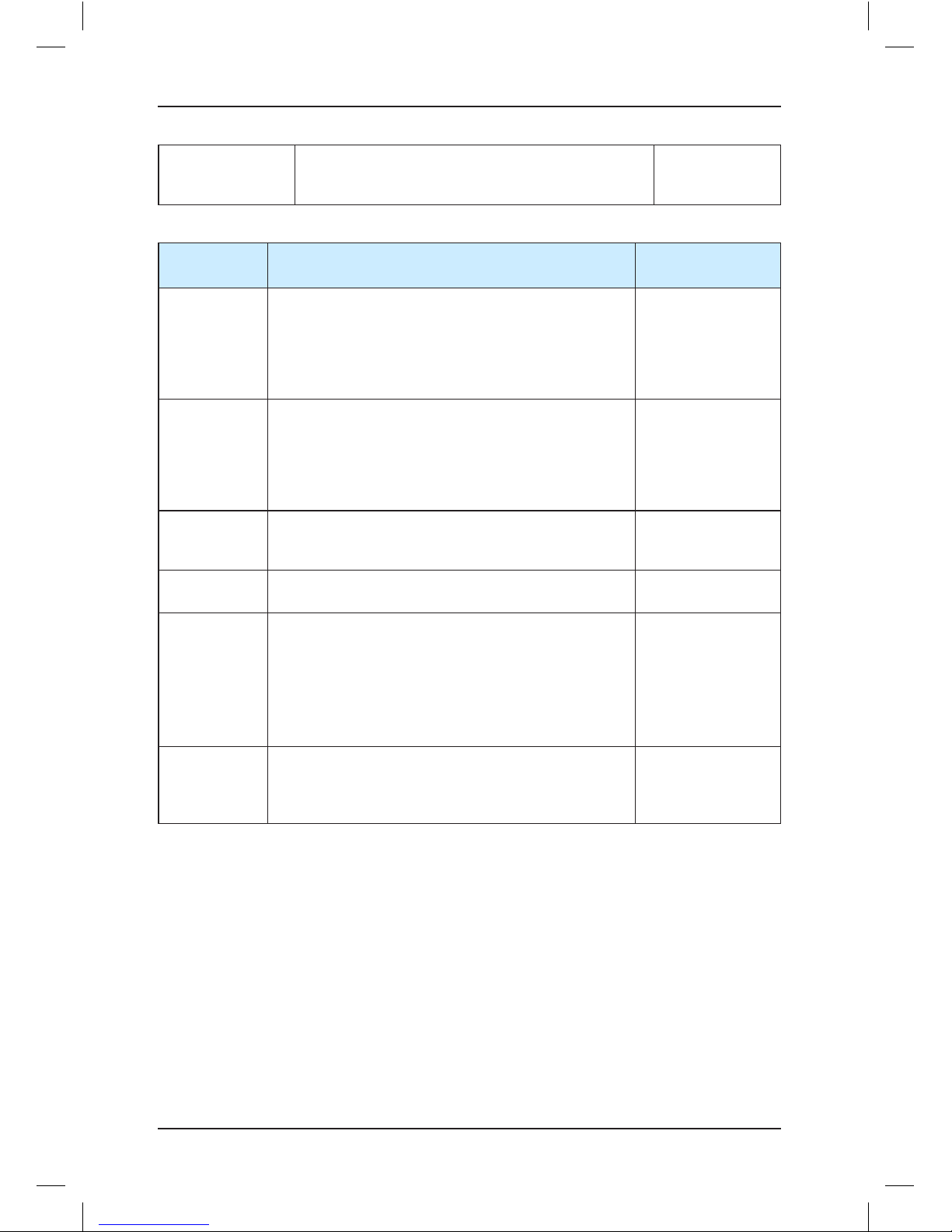
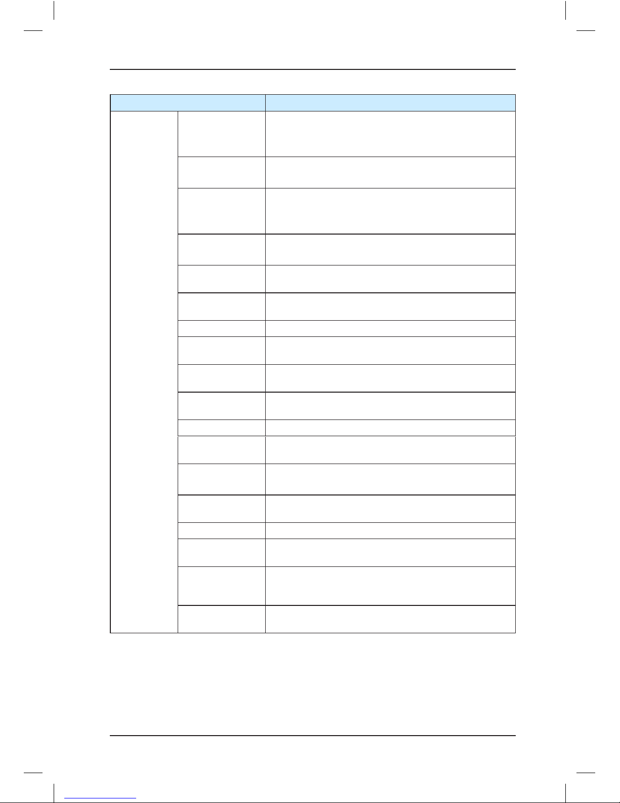
3. Basic function list
Function Description Remarks
Common Running Functions
Integrated control
for synchronous
and asynchronous
motors
It can drive both AC asynchronous motor and
permanent magnetic synchronous motor (PMSM).
Switchover
between the
two types of
motors easily by
modifying F1-25
Full collective
selective
In automatic running or attendant state, this function
enables the elevator to respond both car calls and
hall calls. Passengers at any service oor can call the
elevator by pressing the up call button and down call
button.
Collective
selection set in
FE-00
Door open time
setting
The system automatically determines different door
open time for door open for call, command, protection,
or delay according to the set door open holding time.
Set in group Fb
Door open holding
In automatic running state, passengers can press
the door open button in the car to delay door open to
facilitate goods to be moved in or out.
Set in group Fb
Door machine
service oor setting
You can set the required service oors of the door
machines.
Set in Fb-02 and
Fb-04
Door pre-close
by the door close
button
During door open holding in automatic running state,
passengers can press the door close button to close
the door in advance, which improves the efciency.
-
Floor number
display setting
The system supports display of oor numbers in
combinations of numbers and letters, which meets the
requirements of special conditions.
Set in group FE
Light curtain signal
judgment
If the door is blocked by stuff during door close, the
light curtain acts and the elevator opens the door. This
function is invalid in re emergency state.
-
Independent control
of the front door
and back door
When there are two doors for a car, this function
implements independent and automatic control on the
two doors according to your requirements.
Refer to section
5.2.3 in Chapter 5
Repeat door close
If the door lock is not applied after the elevator
performs door close for a certain time, the elevator
automatically opens the door and then closes the door
repeatedly.
Fb-08 (Door close
protection time)
Auto-leveling
The systems implements automatic accurate leveling
based on the oor pulse counting and up/down leveling
feedback signals.
-
Response at
acceleration
The system allows the elevator to automatically
respond to calls from the service oors during
acceleration.
-
Idle elevator
returning to base
oor
In automatic running state, the elevator automatically
returns to the set parking oor and waits for
passengers if there is no car call or hall call within the
set time.
F9-00 (Idle time
before returning
to base oor)
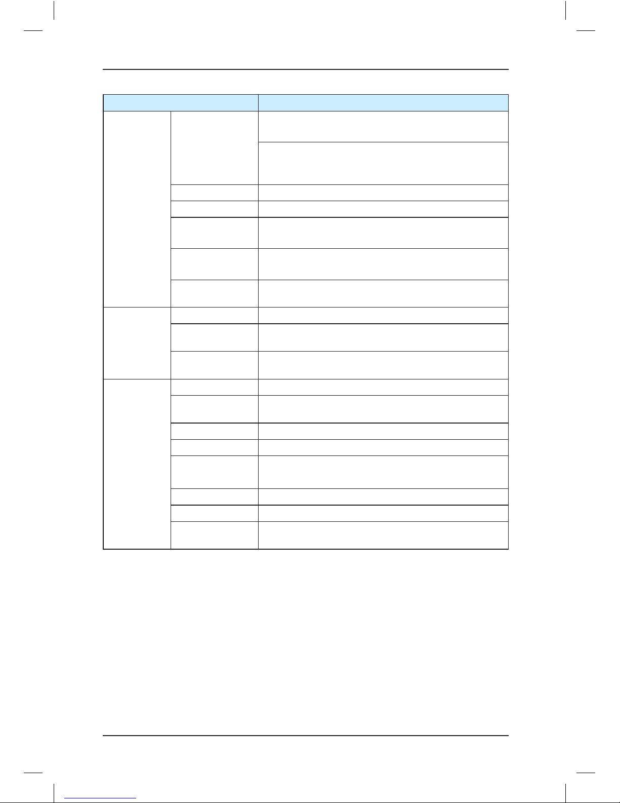
Page 7

Introduction NICE1000
new
User Manual
- 6 -
Landing at another
oor
If the door open time exceeds the door open protection
time but the door open limit signal is still inactive, the
elevator closes the door and then automatically runs to
the next landing oor. The system reports fault Err55.
-
Forced door close
When the door fails to close within the set time due
to the action of the light curtain or safety edge, the
elevator enters the forced door close state, closes the
door slowly, and gives a prompt tone.
-
Service oor setting
You can enable or disable the system service for
certain oors exibly based on actual requirements.
Set in F6-05
Independent
running
The elevator does not respond to any call, and the
door needs to be closed manually. In the case of group
control, the elevator runs independently out of the
group control system.
Enabled when
Bit9 of FE-13 is 1
and independent
running input of
the MCB is active
Attendant running
In attendant state, the running of the elevator is
controlled by the attendant.
-
Low-speed selfrescue
When the elevator is in non-inspection state and
stops at non-leveling area, the elevator automatically
runs to the leveling area at low speed if the safety
requirements are met, and then opens the door.
-
Door control
function
You can set whether the system keeps outputting
commands after door open limit and door close limit
based on the type of the door machine.
-
Car arrival gong
After the elevator arrives at the destination oor, the
CTB gives a prompt tone.
-
Automatic
startup torque
compensation
The system automatically implements startup torque
compensation based on the current car load, achieving
smooth startup and improving the riding comfort.
Set in F8-01
Direct travel ride
The system automatically calculates and generates
the running curves based on the distance, enabling the
elevator to directly stop at the leveling position without
creeping.
-
Automatic
generation of
optimum curve
The system automatically calculates the optimum
speed curve compliant with the human-machine
function principle based on the distance, without being
limited by the number of curves or short oor.
-
Service suspension
output
When the elevator cannot respond to hall calls, the
corresponding terminal outputs the service suspension
signal.
-
Running times
recording
In automatic running state, the system automatically
records the running times of the elevator.
Recorded in F905 and F9-06
Running time
recording
The system automatically records the accumulative
power-on time, working hours, and working days of the
elevator.
Recorded in
F9-03
Page 8
NICE1000
new
User Manual Introduction
- 7 -
Automatic door
open upon door
lock abnormality
If the system detects that the door lock circuit is
abnormal during door open/close, the elevator
automatically opens and closes the door again, and
reports a fault after the set door open/close times is
reached.
Fb-09 (Door open/
close protection
times)
Full-load direct
running
When the car is full-loaded in automatic running state,
the elevator does not respond to hall calls from the
passing oors. These halls calls, however, can still be
registered, and will be executed at next time of running
(in the case of single elevator) or by another elevator
(in the case of parallel control).
-
Overload protection
When the car load exceeds the rated elevator load, the
elevator alarms and stops running.
-
Fault data
recording
The system automatically records detailed information
of faults, which helps improve the efciency of
maintenance and repair.
Set in group FC
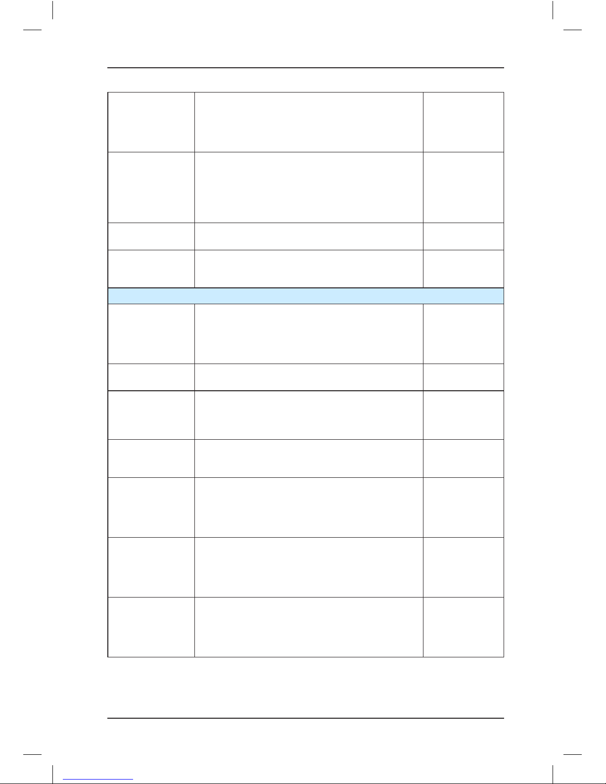
Inspection-related Functions
Shaft auto-tuning
Shaft auto-tuning is required before rst-time automatic
running. During shaft auto-tuning, the elevator runs
from the bottom oor to the top oor at the inspection
speed and automatically records all position signals in
the shaft.
Refer to section
5.1.2
User-dened
parameter display
You can view the parameters that are modied and
different from the default setting.
Set in FP-02
Inspection running
After entering the inspection state, the system cancels
automatic running and related operations. You can
press the up or down call button to make the elevator
jog at the inspection speed.
-
Motor auto-tuning
With simple parameter setting, the system can obtain
the motor parameters no matter whether the motor is
with-load or without load.
Refer to section
5.1.1
Floor position
intelligent
correction
Every time the elevator runs to the terminal oor, the
system automatically checks and corrects the car
position information based on slow-down switch 1, and
eliminates over travel top terminal or bottom terminal
with use of the slow-down switches.
-
Dual-speed for
inspection
Considering inaccurate running control at high
inspection speed but long running time at low
inspection speed, the system provides the dualspeed curve for inspection, which greatly improves the
efciency at inspection.
-
Test running
The test running includes the fatigue test of a new
elevator, car call oor test, hall call test, and tests
such as hall call response forbidden, door open/close
forbidden, terminal oor limit switch shielded, and
overload signal shielded.
Set in F6-10
Page 9
Introduction NICE1000
new
User Manual
- 8 -
Fire Emergency and Security Functions
Returning to
base oor at re
emergency
After receiving a re emergency signal, the elevator
does not respond to any call but directly runs to the re
emergency oor and waits.
F6-03 (Fire
emergency oor)
Fireghter running
After the elevator enters the reghter running mode,
door open/close is implemented by the jog operation
(optional) by using the door open and close buttons
rather than automatically. In addition, the elevator
responds to only car calls and only one call can be
registered once.
F6-68 (Fire
emergency
function selection)
Elevator lock
In automatic running state, when the elevator lock
switch acts or the set elevator time is reached, the
elevator cancels all registered calls, returns to the
elevator lock oor, stops running, and turns off the
lamp and fan in the car.
F6-04 (Elevator
lock oor)
Troubleshooting
based on fault level
Faults are classied into different levels based on the
severity. Different levels of faults are rectied using
different methods.
Refer to Chapter
8
Runaway
prevention
The system detects the running state of the elevator in
real time. If the elevator speed exceeds the limit, the
system immediately stops running of the elevator.
-
Automatic
identication of
power failure
The system automatically identies power failure and
outputs the relay signal for emergency evacuation
automatic switchover to implement emergency
evacuation at power failure.
Y0 especially
used for
emergency
evacuation
switchover
Automatic running
mode switchover at
power failure
For the synchronous motor, when the power supply
is interrupted, the system can perform automatic
switchover between shorting stator braking mode and
controller drive mode, implementing quick and stable
self-rescue.
Shorting stator braking mode: Upon power failure,
UPS is used, the motor stator is shorted, and the brake
is automatically released, making the car move slowly
under the effect of the weighing difference between the
car and the counterweight.
F6-69
(Emergency
evacuation
function selection)
Running direction
identication at
power failure
When the power supply is interrupted, the system
can automatically identify the current car load and
determine the running direction.
F6-69
(Emergency
evacuation
function selection)
Base oor
verication
After detecting a position abnormality, the system runs
the elevator to each oor until reaching the terminal
oor for verication, guaranteeing system security.
-
Passenger
unloading rst upon
fault
The system automatically determines the fault level. If
the safety running conditions are met, the elevator rst
runs to the leveling position to unload passengers.
-
Interference degree
judgment
The system judges the degree of communication
interference.
Viewed in FA-24
Page 10
NICE1000
new
User Manual Introduction
- 9 -
Earthquake
protection
When the earthquake detection device acts and
inputs a signal to the system, the elevator lands at the
nearest oor and stops running. After the earthquake
signal becomes inactive and the fault is reset manually,
the elevator restores to normal running.
-
Independent
working power
supply
The NICE1000new system supports not only threephase 380 VAC but also single-phase 220 VAC to
meet different applications of the power supply system
(such as 220 V UPS)
-
Automatic voltage
identication
The system detects the bus voltage and automatically
adjusts the running speed of the elevator to adapt to
the situation of insufcient power from power supply
(such as emergency UPS).
-
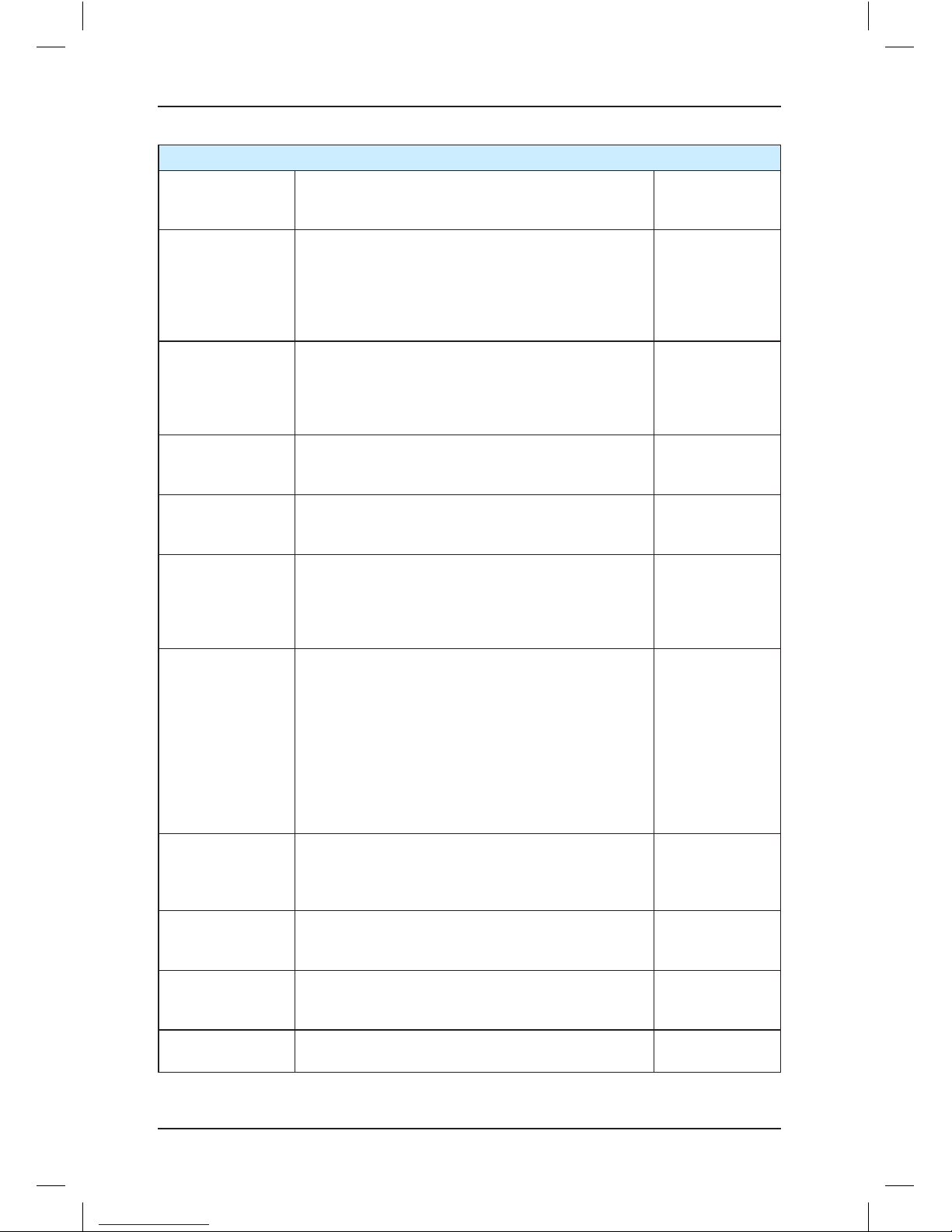
Parallel Control and Other Functions
Parallel control The system supports parallel control of two elevators. Refer to 5.2.2
Dispersed waiting
In parallel control, the elevators can wait at different
oors.
Set in Fd-05
Parallel control exit
If the parallel control exit switch of a certain elevator in
a parallel control system is valid or the time for exiting
the parallel control is reached, the elevator exits
parallel control and runs independently. This does not
affect normal running of the parallel control system.
-
Parallel control
automatic exit
If an elevator in the parallel control system cannot
respond to calls in time due to faults, the elevator
automatically exits the parallel control system and runs
independently. This does not affect normal running of
the parallel control system.
-
Anti-nuisance
function
The system automatically judges the number of
passengers in the car and compares it with the number
of registered car calls. If there are excessive car calls,
the system determines that it is nuisance and cancels
all car calls. In this case, passengers need to register
correct car calls again.
F8-13 (Antinuisance function)
Prompt of non-door
zone stop
The system gives a prompt when the elevator stops at
a non-door zone area due to faults.
-
Interface for
intelligent
residential
management
The system provides an interface for intelligent
residential management to perform remote monitoring
on the state of elevators in the residential district.
Residential
monitoring board
MCTC-MIB
required
Parameter copy
You can upload and download parameters by using
the operation panel MDKE6.
MDKE6 operation
panel required
Energy-Saving Functions
Car energy-saving
If there is no running command within the set time, the
system automatically cuts off the power supply to the
lamp and fan in the car.
F9-01 (Time for
fan and lamp to
be turned off)
Page 11
Introduction NICE1000
new
User Manual
- 10 -
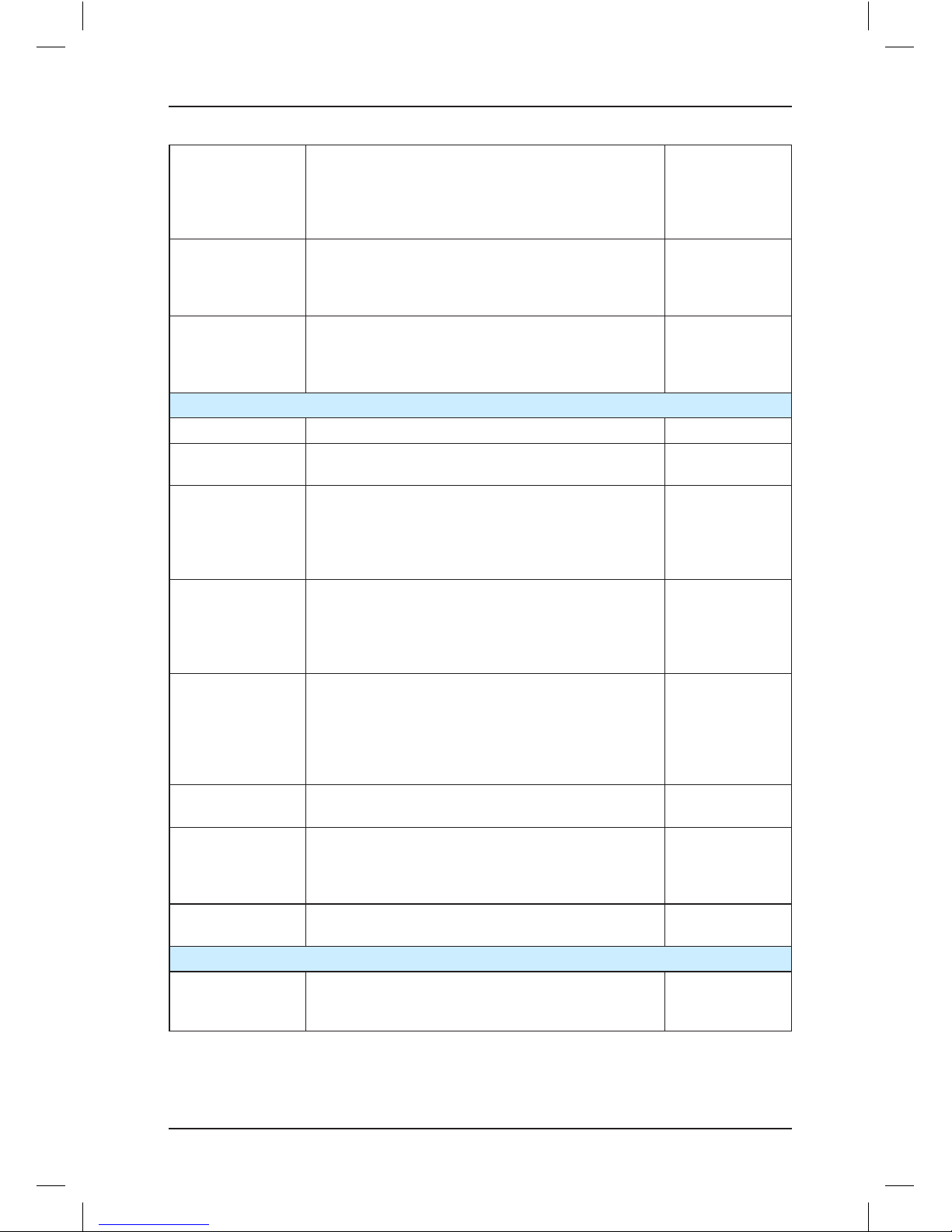
Energy-saving of
idle door machine
After the car lamp is turned off, the system does not
output the door close command, which reduces power
consumption of the door machine.
Set in FE-14
4. Optional function list
Function Description Remarks
Door pre-open
In automatic running state, when the elevator speed is
smaller than 0.2 m/s at normal stop and the door zone
signal is active, the system shorts the door lock by
means of the shorting door lock circuit contactor and
outputs the door open signal, implementing door pre-
open. This improves the elevator use efciency.
Door pre-open
module MCTC-SCB
required
Micro-leveling
After landing at a oor, the elevator may move upward
or downward due to the load change and the car door
is not aligned with the ground, which is inconvenient for
in and out of passengers and goods. In this case, the
system allows the elevator to run to the leveling position
in the door open state at the leveling speed.
Door pre-open
module MCTC-SCB
required
Power failure
emergency
evacuation
For the elevator congured with UPS, the system uses
the UPS to implement low-speed self-rescue in the case
of power failure.
UPS required
Onsite
commissioning
The system can control and monitor running of elevators
by using the NEMS software.
NEMS software
required
Commissioning
by cell phone
The Android cell phone can be connected to the
controller through the external Bluetooth module, and
you can commission and monitor the elevator, and
upload and download parameters by using the cell
phone.
The software does not not supporting English version
currently.
Special Bluetooth
module (MCTCBTM-A) and cell
phone host EDSAP
required
Residential
monitoring
The control system can be connected to the terminal in
the monitoring room. By using the NEMS software, you
can view the oor position, running direction, and fault
state of the elevator.
NEMS, accessories,
and residential
monitoring board
MCTC-MIB required
Page 12

Contents
Preface ................................................................................................................. 1
Introduction ........................................................................................................... 3
Chapter 1 Safety Information and Precautions................................................... 14
1.1 Safety Precautions ....................................................................................................... 14
1.2 General Precautions ..................................................................................................... 17
1.3 Protective Functions ..................................................................................................... 20
Chapter 2 Product Information ........................................................................... 22
2.1 System Conguration of the NICE1000
new ........................................................................................................................ 22
2.2 Designation Rules and Model Description.................................................................... 23
2.3 Models and Specications ............................................................................................ 23
2.4 Technical Specications ............................................................................................... 24
2.5 Physical Appearance and Mounting Dimensions ......................................................... 26
2.6 Optional Parts ............................................................................................................... 28
2.7 Selection of Braking Components ................................................................................ 29
Chapter 3 Mechanical and Electrical Installation ................................................ 34
3.1 Installation Requirements ............................................................................................. 34
3.2 Mechanical Installation ................................................................................................. 35
3.3 Electrical Installation ..................................................................................................... 36
3.4 Selection of Peripheral Electrical Devices .................................................................... 44
3.5 Electrical Wiring Diagram of the NICE1000
new
Control System .................................... 46
3.6 Installation of Shaft Position Signals ............................................................................ 46
Chapter 4 Use of the Commissioning Tools ....................................................... 52
4.1 Use of the LED Operation Panel .................................................................................. 52
Chapter 5 System Commissioning and Application Example ............................. 58
5.1 System Commissioning ................................................................................................ 58
5.2 System Application ....................................................................................................... 70
Chapter 6 Function Code Table .......................................................................... 80
6.1 Function Code Description ........................................................................................... 80
6.2 Function Code Groups ................................................................................................. 80
6.3 Function Code Table ..................................................................................................... 81
Page 13

Chapter 7 Description of Function Codes......................................................... 108
Group F0: Basic Parameters ............................................................................................ 108
Group F1: Motor Parameter ..............................................................................................110
Group F2: Vector Control Parameters ...............................................................................113
Group F3: Running Control Parameters ............................................................................116
Group F4: Floor Parameters..............................................................................................118
Group F5: Input Terminal Parameters .............................................................................. 120
Group F6: Basic Elevator Parameters .............................................................................. 130
Group F7: Output Terminal Parameters ........................................................................... 143
Group F8: Enhanced Function Parameters ...................................................................... 145
Group F9: Time Parameters ............................................................................................. 147
Group FA: Keypad Setting Parameters ............................................................................ 148
Group Fb: Door Function Parameters .............................................................................. 159
Group FC: Protection Function Parameters ..................................................................... 162
Group Fd: Communication Parameters ............................................................................ 165
Group FE: Elevator Function Parameters ........................................................................ 166
Group Fr: Leveling Adjustment Parameters ..................................................................... 170
Group FF: Factory Parameters......................................................................................... 171
Group FP: User Parameters ............................................................................................. 171
Chapter 8 Troubleshooting ............................................................................... 174
8.1 Maintenance ............................................................................................................... 174
8.2 Description of Fault Levels ......................................................................................... 175
8.3 Fault Information and Troubleshooting ....................................................................... 177
Chapter 9 EMC ................................................................................................. 192
9.1 Denition of Terms ...................................................................................................... 192
9.2 Introduction to EMC Standard .................................................................................... 192
9.3 Selection of Peripheral EMC Devices......................................................................... 193
9.4 Shielded Cable ........................................................................................................... 196
9.5 Solutions to Common EMC Interference Problems .................................................... 198
Page 14

1
Safety Information and Precautions
Page 15
Safety Information and Precautions NICE1000
new
User Manual
- 14 -
Chapter 1 Safety Information and Precautions
In this manual, the notices are graded based on the degree of danger:
•
DANGER
indicates that failure to comply with the notice will result in severe
personal injury or even death.
•
WARNING
indicates that failure to comply with the notice will result in potential risk
of severe personal injury or even death.
•
CAUTION
indicates that failure to comply with the notice will result in minor or
moderate personal injury or equipment damage.
In addition,
NOTE
appearing in other chapters indicates that an unintended result or
situation may occur if the notice is not complied with.
The notices in this manual you have to observe are aimed at guaranteeing your personal
safety, as well as to prevent damage to the controller or the parts connected to it. Read this
chapter carefully so that you have a thorough understanding and perform all operations by
following the notices in this chapter. Monarch will assume no liability or responsibility for any
injury or loss caused by improper operation.
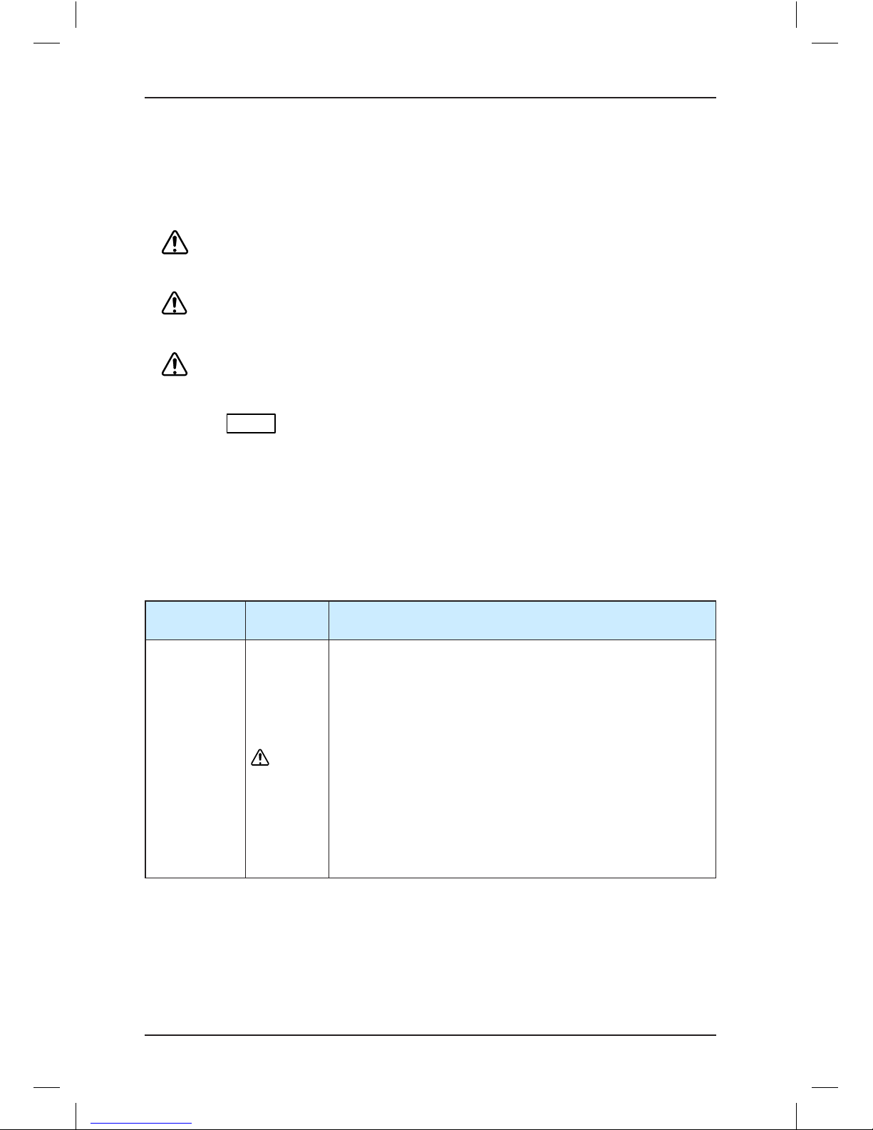
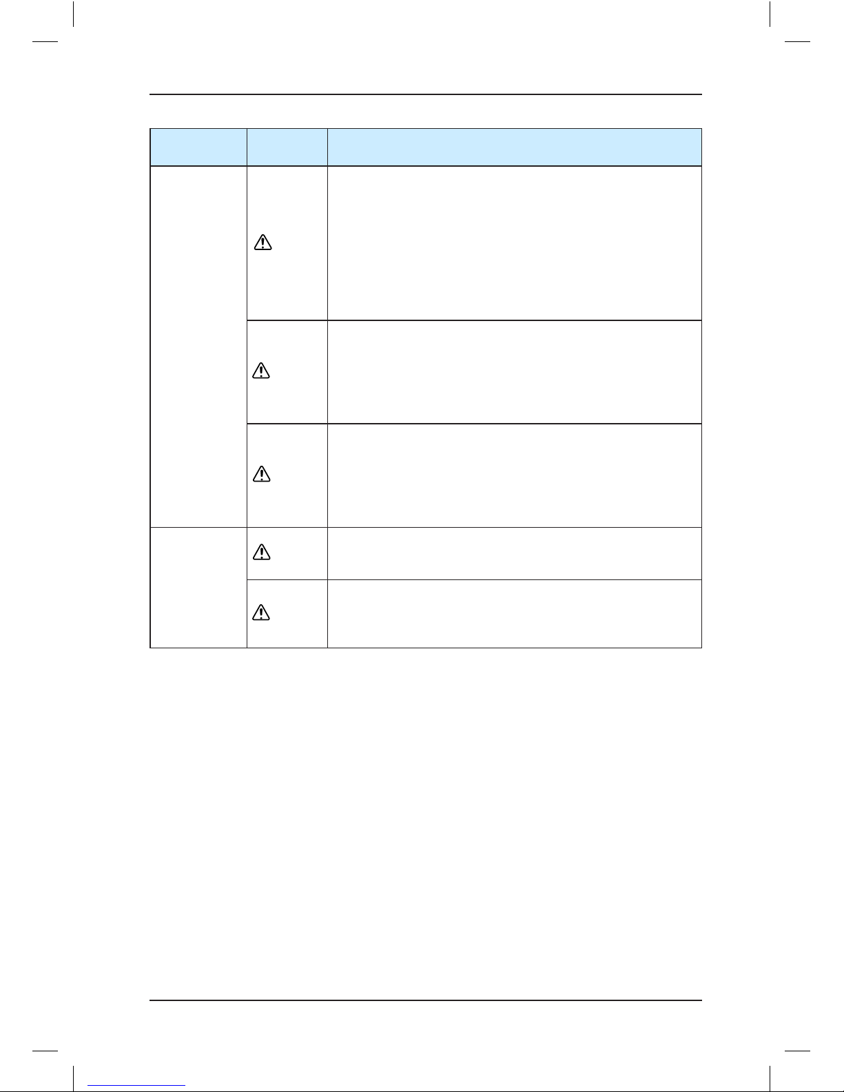
1.1 Safety Precautions
Use Stage
Safety
Grade
Precautions
Before
installation
WARNING
•This controller has hazardous high voltage and the controlled
motor is a dangerous rotating device. Failure to comply with
the notices may result in personal injury or damage to the
property.
•Transportation, installation, operation and maintenance of
the controller can be performed only by qualied personnel
after they get familiar with the safety information in this
manual. This is the prerequisite of safe and stable running of
the equipment.
•Do not open the front cover or touch the power terminals
on the main circuit within 10 minutes after the controller is
powered off. The capacitor on the DC circuit still has residual
high voltage even after power-off. Failure to comply will
result in electric shock.
Page 16
NICE1000
new
User Manual Safety Information and Precautions
- 15 -
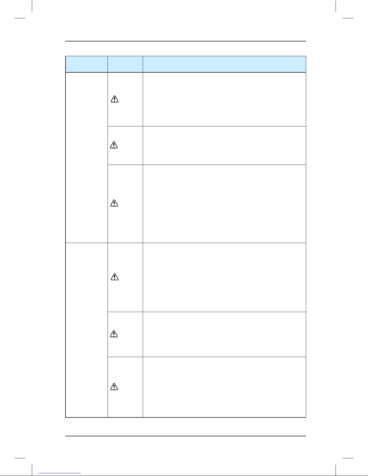
Use Stage
Safety
Grade
Precautions
During
installation
DANGER
•Do not install the equipment if you nd water seepage,
component missing or damage upon unpacking.
•Do not install the equipment if the packing list does not
conform to the product you received.
•Install the equipment on incombustible objects such as
metal, and keep it away from combustible materials. Failure
to comply may result in a re.
WARNING
•Do not loosen the xed screws of the components, especially
the screws with red mark.
•Do not install the controller on vibrating parts. Failure
to comply may result in damage to the equipment or
unexpected accidents.
CAUTION
•Handle the equipment with care during transportation to
prevent damage to the equipment.
•Do not drop wire end or screw into the controller. Failure to
comply will result in damage to the controller.
•Do not use the equipment with damaged or missing
components. Failure to comply will result in personal injury.
•Do not touch the components with your hands. Failure to
comply will result in static electricity damage.
•Install the controller in places free of vibration and direct
sunlight.
At wiring
DANGER
•Wiring must be performed only by qualied personnel under
instructions described in this manual. Failure to comply may
result in unexpected accidents.
•A circuit breaker must be used to isolate the power supply
and the controller. Failure to comply may result in a re.
•Ensure that the power supply is cut off before wiring. Failure
to comply may result in electric shock.
•Tie the controller to ground properly according to the
standard. Failure to comply may result in electric shock.
WARNING
•Never connect the power cables to the output terminals (U,
V, W) of the controller. Pay attention to the marks of the
wiring terminals and ensure correct wiring. Failure to comply
will result in damage to the controller.
•Never connect the braking resistor between the DC bus
terminals (+) and (-). Failure to comply may result in a re.
CAUTION
•Ensure that the cabling satises the EMC requirements and
local codes. Use wire sizes recommended in the manual.
Failure to comply may result in accidents.
•Use the shielded cable for the encoder, and ensure that the
shield is reliably grounded at one end.
•Use a twisted cable with twisted distance of 20−30 mm
as the communication cable, and ensure that the shield is
reliably grounded.
Page 17
Safety Information and Precautions NICE1000
new
User Manual
- 16 -
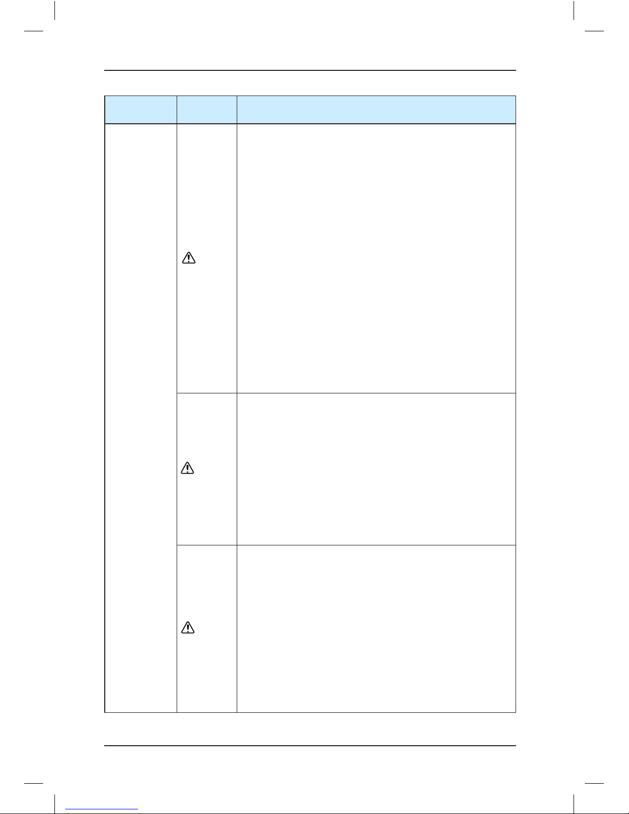
Use Stage
Safety
Grade
Precautions
During
running
DANGER
•All peripheral devices must be connected properly according
to the circuit wiring instructions provided in this manual.
Failure to comply will result in accidents
•Cover the controller properly before power-on to prevent
electric shock.
•Do not open the controller’s cover after power-on. Failure to
comply may result in electric shock.
•Do not touch the controller and peripheral circuits with wet
hand. Failure to comply may result in electric shock.
•Do not touch any I/O terminal of the controller. Failure to
comply may result in electric shock.
•The controller performs safety detection on external strong
power circuits automatically at the beginning of power-on.
Do not touch the U, V, W terminals of the controller or the
motor terminals at the moment. Failure to comply may result
in electric shock.
•Do not touch the fan or the discharging resistor to check the
temperature. Failure to comply will result in personal burnt.
•Signal detection must be performed only by qualied
personnel during operation. Failure to comply will result in
personal injury or damage to the controller.
WARNING
•Do not touch the rotating part of the motor during the motor
auto-tuning or running. Failure to comply will result in
accidents.
•Check that the following requirements are met:
•The voltage class of the power supply is consistent with the
rated voltage class of the controller.
•The input terminals (R, S, T) and output terminals (U, V, W)
are properly connected.
•No short-circuit exists in the peripheral circuit.
•The wiring is secured.
Failure to comply will result in damage to the controller.
CAUTION
•For synchronous motor, ensure that motor auto-tuning is
performed successfully. Perform trial running before resuming
the steel rope so as to make the motor run properly.
•Avoid objects falling into the controller when it is running.
Failure to comply will result in damage to the controller.
•Do not perform the voltage resistance test on any part of the
controller because such test has been done in the factory.
Failure to comply may result in accidents.
•Do not change the default settings of the controller. Failure
to comply will result in damage to the controller.
•Do not start/stop the controller by turning on or off the
contactor. Failure to comply will result in damage to the
controller.
Page 18
NICE1000
new
User Manual Safety Information and Precautions
- 17 -
Use Stage
Safety
Grade
Precautions
During
maintenance
DANGER
•Do not repair or maintain the controller at power-on. Failure
to comply will result in electric shock.
•Repair or maintain the controller when its voltage is lower
than 36 VAC, about 10 minutes after the controller is
powered off. Otherwise, the residual voltage in the capacitor
may result in personal injury.
•Do not allow unqualied personnel to repair or maintain the
controller. Failure to comply will result in personal injury or
damage to the controller.
WARNING
•Repair or maintenance of the controller can be performed
only by the warranty center or qualied personnel authorized
by Monarch. Failure to comply will result in personal injury or
damage to the controller.
•Power supply must be cut off before repair or maintenance
of the controller.
CAUTION
•Set the parameters again after the controller is replaced. All
the pluggable components must be plugged or removed only
after power-off.
•Strictly obey the laws and regulations and repair and
maintain the elevator equipment periodically. Only timely
troubleshooting can ensure the safety of passengers.
Disposal
CAUTION
The packaging materials, screws and terminal blocks can be
re-used and it is suggested that you keep them well for future
use.
WARNING
The electrolytic capacitors on the main circuits and PCB may
explode when they are burnt. Poisonous gas is generated when
the plastic parts are burnt. Treat them as ordinary industrial
waste.
1.2 General Precautions
1. Requirement on the residual current device (RCD)
The controller generates high leakage current during running, which flows through the
protective earthing conductor. Thus install a type- B RCD at primary side of the power
supply. When selecting the RCD, you should consider the transient and steady-state leakage
current to ground that may be generated at startup and during running of the controller. You
can select a specialized RCD with the function of suppressing high harmonics or a generalpurpose RCD with relatively large residual current.
2. High leakage current warning
The controller generates high leakage current during running, which flows through the
protective earthing conductor. Earth connection must be done before connection of power
supply. Earthing shall comply with local regulations and related IEC standards.
Page 19
Safety Information and Precautions NICE1000
new
User Manual
- 18 -
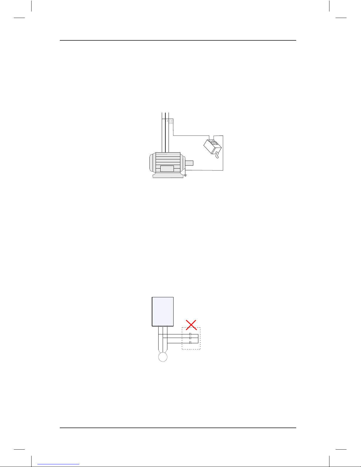
3. Motor insulation test
Perform the insulation test when the motor is used for the rst time, or when it is reused
after being stored for a long time, or in a regular check-up, in order to prevent the poor
insulation of motor windings from damaging the controller. The motor must be disconnected
from the controller during the insulation test. A 500-V mega-Ohm meter is recommended for
the test. Ensure that the insulation resistance is not less than 5 MΩ.
U V W
Megger
Motor input
terminals
Ground
4. Thermal protection of motor
If the rated capacity of the motor selected does not match that of the controller, especially
when the rated power of the controller is greater than that of the motor, adjust the motor
protection parameters on the operation panel of the controller or install a thermal relay for
the motor circuit for protection.
5. Motor heat and noise
The output of the controller is pulse width modulation (PWM) wave with certain harmonic
wave, and therefore, the motor temperature rise, noise, and vibration are slightly greater
than those at running with the mains frequency.
6. Voltage-sensitive device or capacitor on the output side of the controller
The controller outputs PWM waves, and therefore, do not install the capacitor for improving
power factor or lightning protection voltage-sensitive resistor on the output side of the
controller. Otherwise, the controller may suffer transient overcurrent or even be damaged.
M
U V W
Capacitor or varistor
Controller
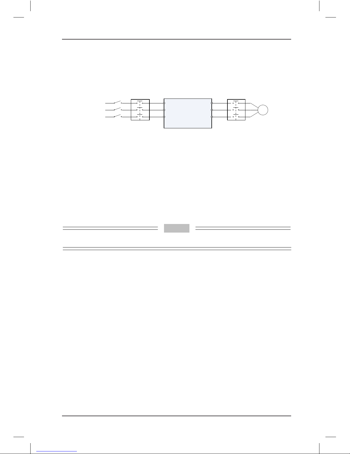
7. Contactor on the input and output sides of the controller
When a contactor is installed between the input side of the controller and the power supply,
the controller must not be started or stopped by turning on or off the contactor.
If the controller has to be operated by the contactor, ensure that the time interval between
switching is at least one hour because frequent charge and discharge will shorten the
Page 20
NICE1000
new
User Manual Safety Information and Precautions
- 19 -
service life of the capacitor inside the controller.
When a contactor is installed between the output side of the controller and the motor, do not
turn off the contactor when the controller is active. Otherwise, modules inside the controller
may be damaged.
380 VAC
50/60 Hz
R
S
T
V
W
U
Contactor KM
Contactor KM or
other switches
M
Controller
8. Use outside the rated voltage
The controller must not be used outside the allowable voltage range specified in this
manual. Otherwise, components inside the controller may be damaged. If required, use a
corresponding voltage step-up or step-down device.
9. Surge suppressor
The controller has a built-in voltage dependent resistor (VDR) for suppressing the surge
voltage generated when the inductive loads (electromagnetic contactor, electromagnetic
relay, solenoid valve, electromagnetic coil and electromagnetic brake) around the controller
are switched on or off. If the inductive loads generate very high surge voltage, use a surge
suppressor for the inductive load or use a surge suppressor together with a diode.
Note
Do not connect the surge suppressor on the output side of the controller.
10. Altitude and de-rating
In places where the altitude is above 1000 m and the cooling effect reduces due to thin air, it
is necessary to de-rate the controller. Contact Monarch for technical support.
11. Disposal
The electrolytic capacitors on the main circuits and PCB may explode when they are
burnt. Poisonous gas is generated when the plastic parts are burnt. Treat them as ordinary
industrial waste.
12. Adaptable motor
The controller is adaptable to squirrel-cage asynchronous motor or AC PMSM. Select a
proper controller according to motor nameplate.
The default parameters configured inside the controller are squirrel-cage asynchronous
motor parameters. It is still necessary to perform motor auto-tuning or modify the default
values based on actual conditions. Otherwise, the running effect and protection performance
will be affected. For PMSM, motor auto-tuning must be performed.
13. Precautions on selecting residual-current circuit breaker (RCCB)
Tripping may be caused if an improper RCCB is selected when the controller drives the
motor. This is because the output wave of the controller has high harmonics and the motor
Page 21

Safety Information and Precautions NICE1000
new
User Manual
- 20 -
cable and the cable connecting the controller and the motor produce leakage current, which
is much larger than the current when the motor runs at the mains frequency.
Thus, it is necessary to determine the proper RCCB sensitivity based on the general
leakage current of the cables and the motor. The leakage current is dependent on the motor
capacity, cable length, insulation class and wiring method. Generally, the leakage current
on the output side of the controller is three times of the current when the motor runs at the
mains frequency.
1.3 Protective Functions
Adopting different protective functions for different levels of faults, the NICE1000
new
provides
the elevator running system with full abnormality protection. For detailed solutions to the
faults, see chapter 8.
Faults of the controller are classied as follows:
1. Speed abnormal
The controller monitors the encoder feedback speed and output torque. Once the
feedback speed exceeds the limit or the deviation between the torque limit and the speed
feedback is too large, the controller performs protection immediately, reports an alarm
and prohibits running.
2. Drive control abnormal
The related faults include drive overcurrent, overvoltage/undervoltage, power input/
output phase loss, overload, and storage abnormality. If such a fault occurs, the controller
performs protection immediately, stops output, applies the brake and prohibits running.
3. Encoder abnormal
The related faults include encoder phase loss, direction reversing, wire-breaking, and
pulse interference. If such a fault occurs, the controller performs protection immediately to
avoid unexpected accidents. If pulse interference is large, the controller reports an alarm
immediately. If pulse interference is small, the controller performs position correction
every time it receives a leveling signal and clears the accumulative error.
4. Leveling sensor abnormal
The related faults include sensor failure or sensor stuck. The controller judges whether a
fault occurs based on the leveling signal change. If the leveling signal does not change
within the set time, the system reports an alarm.
5. Floor data abnormal
The system stores the oor information through the shaft auto-tuning. If the oor data is
abnormal, the system prompts the fault information at the rst-time running. During actual
running, the controller continuously compares position information input by DIs with the
stored oor data. If the deviation is large, the system reports an alarm.
Page 22

2
Product Information
Page 23
Product Information NICE1000
new
User Manual
- 22 -
Chapter 2 Product Information
2.1 System Conguration of the NICE1000
new
The NICE1000
new
series integrated elevator control system combines the functions of both
elevator controller and high-performance vector control AC drive. As a high-performance
vector drive and control elevator system, it meets the standard applications of the elevator.
Users can also congure the optional door pre-open module and remote monitoring system
to meet requirements for more intelligent applications.
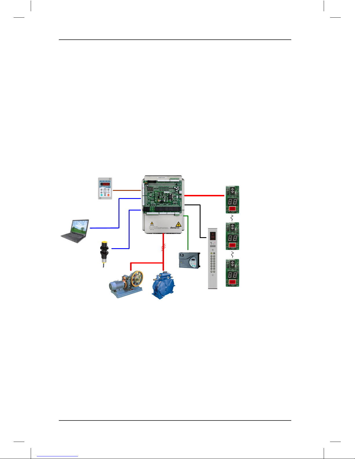
The following gure shows the system components.
Figure 2-1 System components of the NICE1000
new
Operation
box
LED operation
panel (MDKE)
Hall display board
Host
computer
NICE1000
new
integrated controller
Door machine
controller
Load cell
MF.K
RUN
STOP
RES
QUICK
PRG ENTER
RUN
LOCAL/REMOT FED/REV TUNE/TC
RPM
%
A VHz
Synchronous or asynchronous motor
Page 24
NICE1000
new
User Manual Product Information
- 23 -
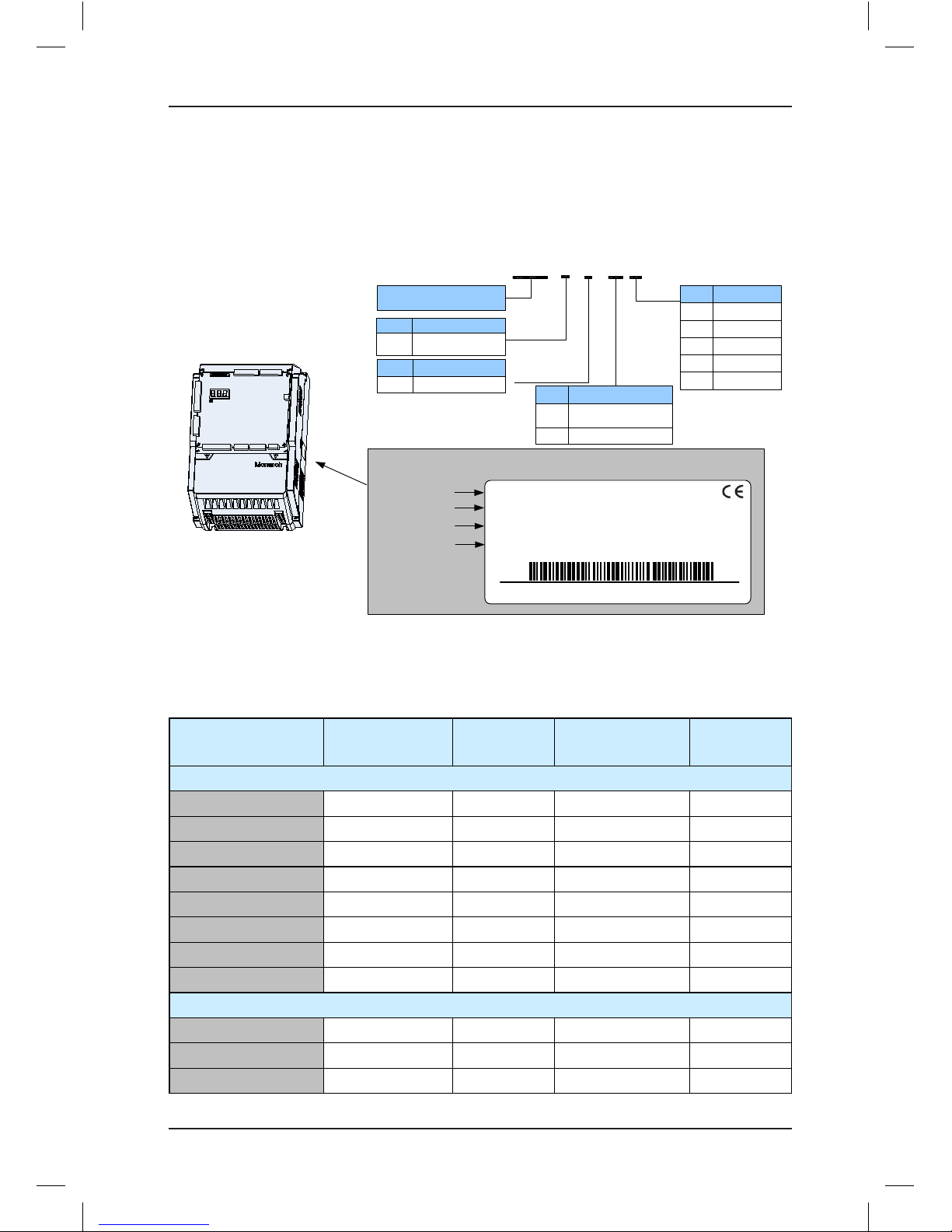
2.2 Designation Rules and Model Description
2.2.1 Designation Rules and Nameplate
Figure 2-2 Designation rules and nameplate of the NICE1000
new
Nameplate
Controller model
Rated input
Rated output
Manufacturing SN
NICE–L–H–40 15
NICE series integrated
elevator controller
H 1000
new
Mark
Motor Type
L
Mark Controller Type
Specialized for
elevators
20
Single-phase/
Three-phase 220 V
Mark
Voltage Class
40
Three-phase 380 V
02 2.2 kW
Mark
03 3.7 kW
... ...
Power Class
30 30 kW
45 45 kW
Nameplate
position
MODEL: NICE-L-H-4015
INPUT: 3PH AC 380~440V 36A 50/60Hz
OUTPUT: 3PH AC 0~440V 33A 0~90Hz 15KW
Suzhou MONARCH Control Technology Co.Ltd
S/N: 010150602803825403
NICE1000
new
Integrated elevator
controller
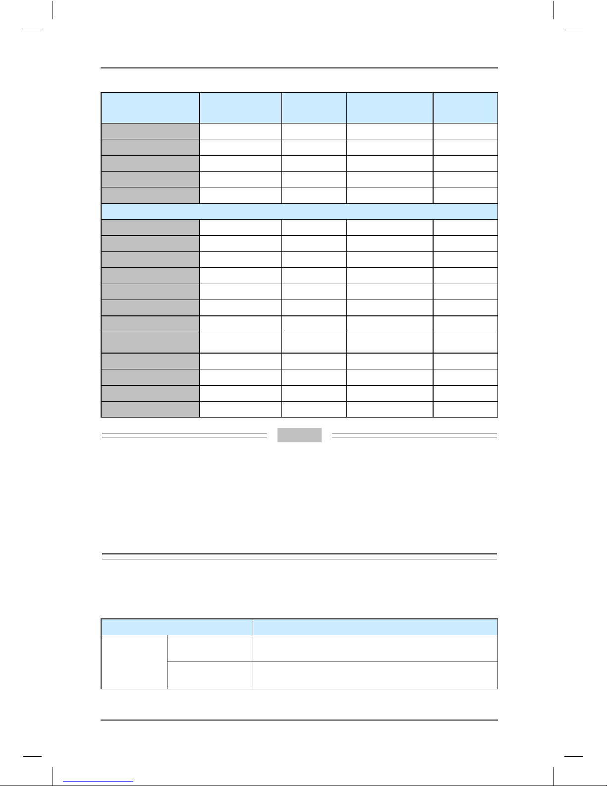
2.3 Models and Specications
Table 2-1 NICE1000
new
models and specications
Controller Model
Power Capacity
(kVA)
Input Current
(A)
Output Current
(A)
Motor Power
(kW)
Single-phase 220 V, range: -15% to 20%
NICE-L-H-2002 2.0 9.2 5.2 1.1
NICE-L-H-2003 2.9 13.3 7.5 1.5
220-NICE-L-H-4007 3.9 17.9 10.3 2.2
220-NICE-L-H-4011 5.9 25.3 15.5 3.7
220-NICE-L-H-4015 7.3 31.3 19 4.0
220-NICE-L-H-4018 8.6 34.6 22.5 5.5
220-NICE-L-H-4022 10.6 42.6 27.7 11
220-NICE-L-H-4030 13.1 52.6 34.6 15
Three-phase 220 V, range: -15% to 20%
NICE-L-H-2002 4.0 11.0 9.6 2.2
NICE-L-H-2003 5.9 17.0 14.0 3.7
220-NICE-L-H-4007 7.0 20.5 18.0 4.0
Page 25
Product Information NICE1000
new
User Manual
- 24 -
Controller Model
Power Capacity
(kVA)
Input Current
(A)
Output Current
(A)
Motor Power
(kW)
220-NICE-L-H-4011 10.0 29.0 27.0 5.5
220-NICE-L-H-4015 12.6 36.0 33.0 7.5
220-NICE-L-H-4018 15.0 41.0 39.0 11.0
220-NICE-L-H-4022 18.3 49.0 48.0 15.0
220-NICE-L-H-4030 23.0 62.0 60.0 18.5
Three-phase 380 V, range: -15% to 20%
NICE-L-H-4002 4.0 6.5 5.1 2.2
NICE-L-H-4003 5.9 10.5 9.0 3.7
NICE-L-H-4005 8.9 14.8 13.0 5.5
NICE-L-H-4007 11.0 20.5 18.0 7.5
NICE-L-H-4011 17.0 29.0 27.0 11.0
NICE-L-H-4015 21.0 36.0 33.0 15.0
NICE-L-H-4018 24.0 41.0 39.0 18.5
NICE-L-H-4022 30.0 49.5 48.0 22.0
NICE-L-H-4030 40.0 62.0 60.0 30.0
NICE-L-H-4037 57.0 77.0 75.0 37.0
NICE-L-H-4045 69.0 93.0 91.0 45.0
NICE-L-H-4055 85.0 113.0 112.0 55.0
Note
1. In terms of single-phase and three-phase 220 VAC, NICE-L-C-2002 and NICE-L-C-2003 are
specially designed for 220 VAC. The other models that are marked by prexing "220-" are modied
from the three-phase 380 VAC models.
2. Same models are available for single-phase 220 VAC and three-phase 220 VAC. Pay attentions
to the power rating of the adaptable motor during the use.
3. Select the proper controller output current based on the rated motor current. Ensure that the
controller output current is equal to or greater than the rated motor current.
4. If you require higher voltage or power rating, contact Monarch.
2.4 Technical Specications
Table 2-2 Technical specications of the NICE1000
new
Item Specication
Basic
specications
Maximum
frequency
99 Hz
Carrier frequency
2–16 kHz, adjusted automatically based on the load
features
Page 26
NICE1000
new
User Manual Product Information
- 25 -
Item Specication
Basic
specications
Motor control mode
Sensorless vector control (SVC)
Closed-loop vector control (CLVC)
Voltage/Frequency (V/F) control
Startup torque
0.5 Hz: 180% (SVC)
0 Hz: 200% (CLVC)
Speed adjustment
range
1:100 (SVC)
1:1000 (CLVC)
1:50 (V/F)
Speed stability
accuracy
±0.5% (SVC)
±0.05% (CLVC)
Torque control
accuracy
±5% (CLVC)
Overload
60s for 150% of the rated current, 1s for 200% of the rated
current
Motor auto-tuning With-load auto-tuning; no-load auto-tuning
Distance control
Direct travel ride mode in which the leveling position can
be adjusted exibly
Acceleration/
Deceleration curve
N curves generated automatically
Slow-down
New reliable slow-down function, automatically identifying
the position of the slow-down shelf
Shaft auto-tuning 32-bit data, recording the position in the shaft accurately
Leveling
adjustment
Flexible and easy leveling adjustment function
Startup torque
compensation
Load cell startup pre-torque compensation
No-load-cell startup pre-torque self-adaption
Test function
Easy to implement multiple elevators commissioning
functions.
Fault protection Solutions to different levels of elevator faults
Intelligent
management
Remote monitoring, user management, and group control
adjustment
Security check of
peripheral devices
after power-on
Security check of peripheral devices, such as grounding
and short circuit, after power-on
Status monitor
Monitoring the state of feedback signals to ensure that the
elevator works properly
Page 27
Product Information NICE1000
new
User Manual
- 26 -
Item Specication
I/O feature
Digital input (DI)
24 x DI
Input specication: 24 V, 5 mA
3 higher-voltage detection input terminals of safety circuit
and door lock circuit
Input specication: 95−125 V
Floor input/output 50 oor button inputs/outputs; functions set exibly
Analog input (AI) AI (voltage range: –10 V to +10 V)
Communication
port
1 CANbus communication ports
1 Modbus communication port
Output terminal
block
27 relay outputs
The terminals can be allocated with different functions.
Encoder interface
Supporting different encoders by using an optional PG
card
Operation and
display
Keypad Used for shaft auto-tuning
LED operation
panel
5-digit LED display, querying/modifying most parameters
and monitoring the system state
NEMS software
Connecting the control system and the host computer,
convenient for querying/motoring the system state.
Environment
Altitude Below 1000 m (de-rated 1% for each 100 m higher)
Ambient
temperature
–10°C to 50°C (de-rated if the ambient temperature is
above 40°C)
Humidity Maximum relative humidity 95%, non-condensing
Vibration Maximum vibration: 5.9 m/s2 (0.6 g)
Storage
temperature
-20°C to 60°C
IP level IP20
Pollution degree PD2
Power distribution
system
TN, TT
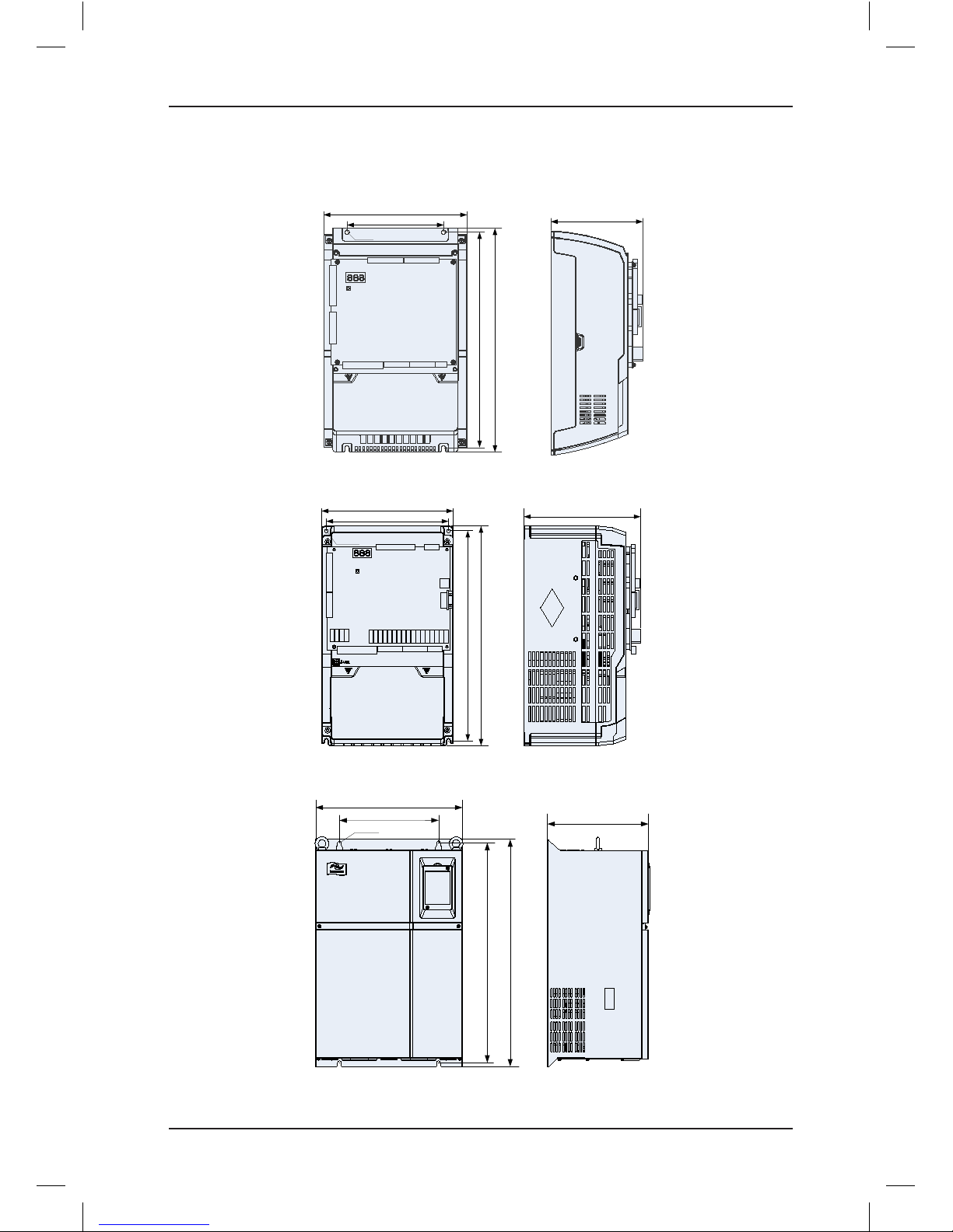
2.5 Physical Appearance and Mounting Dimensions
The following gures show the physical appearance and mounting dimensions of the three
different structures of the NICE1000
new
.
Page 28
NICE1000
new
User Manual Product Information
- 27 -
Figure 2-3 Physical appearance and mounting dimensions of the NICE1000
new
1. L structure, 2.2–15 kW
A
B
W
H
D
Φ
2. L structure, 18–22 KW, 30 –37 KW
A
B
W
H
D
Φ
3. L structure, 45–55 kW
D
A
Φ
B
H
W
Page 29
Product Information NICE1000
new
User Manual
- 28 -
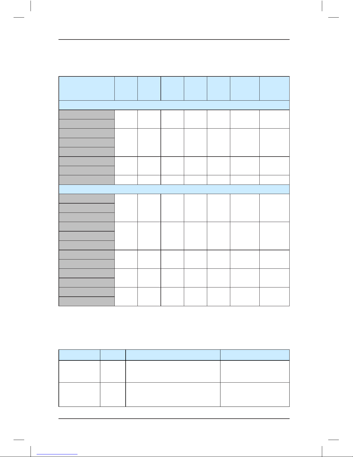
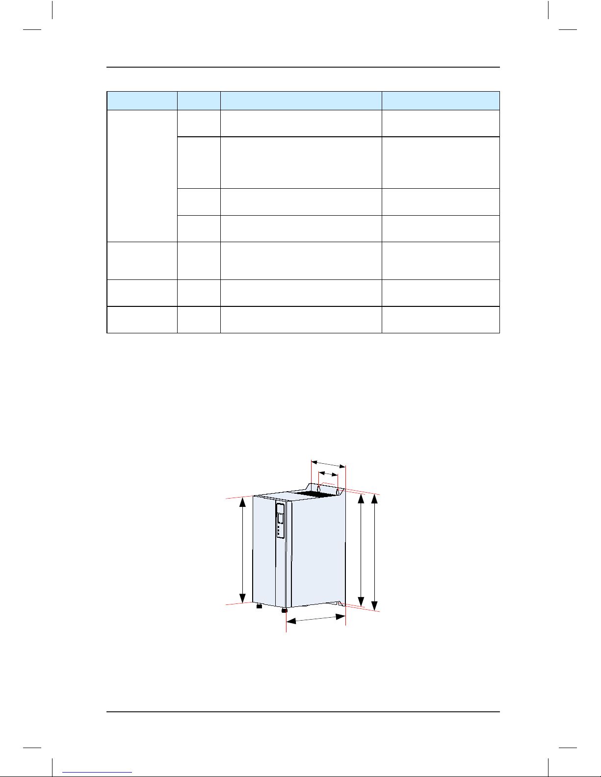
The following table lists the mounting dimensions of different models.
Table 2-3 Mounting dimensions of the NICE1000
new
Controller Model
A
(mm)B(mm)H(mm)
W (mm)
D
(mm)
Hole
Diameter
(mm)
Gross
Weight
(kg)
Single-phase/Three-phase 220 V, range: -15% to 20%
NICE-L-H-2002
150 334.5 347 223 143 6.5 5.5
NICE-L-H-2003
220-NICE-L-H-4007
150 334.5 347 223 173.5 6.5 7220-NICE-L-H-4011
220-NICE-L-H-4015
220-NICE-L-H-4018
195 335 350 210 192 6 9.1
220-NICE-L-H-4022
220-NICE-L-H-4030 230 380 400 250 220 7 17
Three-phase 380 V, range: -15% to 20%
NICE-L-H-4002
150 334.5 347 223 143 6.5 5.5NICE-L-H-4003
NICE-L-H-4005
NICE-L -H-4007
150 334.5 347 223 173.5 6.5 7NICE-L -H-4011
NICE-L -H-4015
NICE-L-H-4018
195 335 350 210 192 6 9.1
NICE-L-H-4022
NICE-L-H-4030
230 380 400 250 220 7 17
NICE-L-H-4037
NICE-L-H-4045
260 580 600 385 265 10 32
NICE-L-H-4055
2.6 Optional Parts
If any optional part in the following table is required, specify it in your order.
Table 2-4 Optional parts of the NICE1000
new
Name Model Function Remark
External
braking unit
MDBUN
It is provided for the NICE1000new of
37 kW and above.
For details, see section
2.7 "Selection of Braking
Components".
Energy
feedback
unit
MCTC-
AFE
It is used for energy saving. This unit
feeds back the electricity generated
during braking to the grid.
-
Page 30
NICE1000
new
User Manual Product Information
- 29 -
Name Model Function Remark
PG card
MCTCPG-A2
It is used to adapt to the push-pull and
open-collector incremental encoders.
-
MCTCPG-D
It is used to adapt to the UVW
differential encoder and applied to
synchronous motor.
It requires 5 V power supply.
-
MCTCPG-E
It is used to adapt to the SIN/COS
encoder.
-
MCTCPG-F1
It is used to adapt to the absolute
encoder (Heidenhain ECN413/1313)
External LED
operation panel
MDKE
It is the external LED display and
operation panel.
It provides the RJ45
interface for connecting to
the controller.
External LED
operation panel
MDKE6
It is the external LED display and
operation panel.
It can be used for copying
parameters.
Extension cable MDCAB
It is a standard 8-core network cable
and can be connected to MDKE.
The cable length is 3 m in
the standard conguration.
2.7 Selection of Braking Components
The NICE1000
new
models of 30 kW and below have a built-in braking unit, and you only need
to connect an external braking resistor between PB and + terminals. For models above 30
kW, you need to install a braking unit and a braking resistor externally.
The following gure shows the appearance and dimensions of the braking unit.
Figure 2-4 Appearance and dimensions of braking unit
φ5
110
60
236 247
224
165
Unit: mm
Select the braking resistor based on the conguration listed in the following table.
Page 31

Product Information NICE1000
new
User Manual
- 30 -
Table 2-5 Braking resistor selection for the NICE1000
new
models
Controller Model
Power of
Adaptable
Motor (kW)
Max.
Resistance
(Ω)
Min.
Resistance
(Ω)
Power of
Braking
Resistor (W)
Braking Unit
Single-phase 220 V, range: -15% to 20%
NICE-L-H-2002 1.1 145.0 125.0 300
Built-in
NICE-L-H-2003 1.5 105.0 90.0 450
220-NICE-L-H-4007 2.2 72.0 63.0 600
220-NICE-L-H-4011 3.7 43.0 37.0 1100
220-NICE-L-H-4015 4.0 40.0 35.0 1200
220-NICE-L-H-4018 5.5 29.0 25.0 1600
220-NICE-L-H-4022 11.0 18.0 16.0 3500
Built-in
220-NICE-L-H-4030 15.0 13.0 13.0 4500
Three-phase 220 V, range: -15% to 20%
NICE-L-H-2002 2.2 72.0 65.0 600
Built-in
NICE-L-H-2003 3.7 54.0 50.0 1100
220-NICE-L-H-4007 4.0 40.0 35.0 1200
220-NICE-L-H-4011 5.5 29.0 25.0 1600
220-NICE-L-H-4015 7.5 26.0 22.0 2500
220-NICE-L-H-4018 11.0 14.5 13.0 3500
220-NICE-L-H-4022 15.0 13.0 12.5 4500
220-NICE-L-H-4030 18.5 12.5 12.0 5500
Three-phase 380 V, range: -15% to 20%
NICE-L-H-4002 2.2 290 230 600
Built-in
NICE-L-H-4003 3.7 170 135 1100
NICE-L-H-4005 5.5 115 90 1600
NICE-L-H-4007 7.5 85 65 2500
NICE-L-H-4011 11 55 43 3500
NICE-L-H-4015 15 43 35 4500
NICE-L-H-4018 18.5 34.0 25 5500
NICE-L-H-4022 22 24 22 6500
NICE-L-H-4030 30 20 16 9000
NICE-L-H-4037 37 16.0 13 11000 MDBUN-60-T
NICE-L-H-4045 45 14.0 11 13500 MDBUN-60-T
NICE-L-H-4055 55 12.0 10 16500 MDBUN-90-T
Page 32

NICE1000
new
User Manual Product Information
- 31 -
Note
1. The preceding conguration takes the synchronous motor as an example. The asynchronous
motor has poor energy transfer efciency, and you can reduce the power of the braking resistor or
increase the resistance of the braking resistor.
2. It is recommended that you select the braking resistor closest to the minimum resistance.
Page 33

Product Information NICE1000
new
User Manual
- 32 -
Page 34

3
Mechanical and Electrical Installation
Page 35

Mechanical and Electrical Installation NICE1000
new
User Manual
- 34 -
Chapter 3 Mechanical and Electrical Installation
3.1 Installation Requirements
3.1.1 Installation Environment Requirements
Item Requirements
Ambient temperature -10°C to 50°C
Heat dissipation
Install the controller on the surface of an incombustible object, and
ensure that there is sufcient space around for heat dissipation.
Install the controller vertically on the support using screws.
Mounting location
Free from direct sunlight, high humidity and condensation
Free from corrosive, explosive and combustible gas
Free from oil dirt, dust and metal powder
Vibration Less than 0.6 g
Protective enclosure
The controllers of plastic housing are whole-unit built-in products
operated through remote control and need to be installed in the nal
system. The nal system must have the required reproof cover,
electrical protective cover and mechanical protective cover, and satisfy
the regional laws & regulations and related IEC requirements.
3.1.2 Installation Clearance Requirements
The clearance that needs to be reserved varies with the power class of the NICE1000
new
, as
shown in the following gure.
Figure 3-1 Clearance around the NICE1000
new
for installation
B
B
A
A
Hot air
Cold air
1.1-18.5 kW
A ≥ 10 mm
B ≥ 100 mm
22-45 kW
A ≥ 50 mm
B ≥ 100 mm
Installation clearance requirements
on the NICE1000
new
of different
power classes
Power Class
Clearance Requirements
The controller should be
installed vertically upward.
NICE1000
new
Page 36

NICE1000
new
User Manual Mechanical and Electrical Installation
- 35 -
3.2 Mechanical Installation
The NICE1000
new
is installed vertically upward on the support with screws fixed into the four
mounting holes, as shown in the following gure.
Figure 3-2 Diagram of mounting holes
4-M5x15 bolt
4-M5x15 screw
4-M5x15 washer
Fixing
backplane
NICE1000
new
integrated
elevator
controller
4-M6x15 bolt
4-M6x15 screw
4-M6x15 washer
1.1 kW
≤ P ≤
15 kW
18.5 kW
≤ P ≤
45 kW
2.5 Nm
With fixing
washer
Tightening
torque
3.5 Nm
With fixing
washer
Fastener
The controller is generally installed in the control cabinet of the elevator equipment room.
Pay attention to the following points when designing the control cabinet:
1. The temperature inside the cabinet must not rise to 10°C higher than the temperature
outside the cabinet.
2. A closed control cabinet must be congured with a fan (or other air cooling device such
as air conditioner) to ensure air circulation.
3. The air from the fan must not blow directly to the drive unit because this easily causes
dust adhesion and further a fault on the drive unit.
4. A vent must be available at bottom of the control cabinet to form bottom-up air flow,
which prevents heat island effect on the surface of components or partial thermal
conductivity effect.
5. If the fan does not meet the cooling requirements, install an air conditioner in the cabinet
or in the equipment room. Note that the temperature inside the cabinet must not be too
low; otherwise, condensation may occur, causing short-circuit of components.
6. For special environment where the temperature is high but cannot be reduced
effectively, de-rate the controller during use.
Page 37

Mechanical and Electrical Installation NICE1000
new
User Manual
- 36 -
3.3 Electrical Installation
3.3.1 Terminal Arrangement and Wiring Description
■Terminal Arrangement
The following gure shows terminal arrangement of the NICE1000
new
.
Figure 3-3 Terminal arrangement of the NICE1000
new
CN4
CN12
S1
J9 J10
ER
OK
CAN
Reserved
CN1
CN6
CN3
CN8CN7 CN9
MCTC-MCB-H
J12
CN5
CN2
CN10
■Description of Main Circuit Terminals
The following gure shows main circuit terminal arrangement.
Figure 3-4 Main circuit terminal arrangement
R
S
T
PB
U
V
W
POWER MOTOR
Page 38

NICE1000
new
User Manual Mechanical and Electrical Installation
- 37 -
Figure 3-5 Wiring of the main circuit
R
S
T
PB
U
V
W
POWER MOTOR
Three-phase AC
power supply
Safety contactor
Braking resistor
(For models of below 37 kW)
Braking unit
R
S
T
PB
U
V
W
POWER
MOTOR
Three-phase AC
power supply
Safety contactor
Braking resistor
MDBUN
Jumper bar
(For models of 37 kW and above)
Table 3-1 Description of main circuit terminals
Terminal Name Description
R, S, T
Three-phase power input
terminals
Provide three-phase power supply.
(+), (-)
Positive and negative
terminals of DC bus
Connect the external braking unit and energy feedback
unit for models of 37 kW and above.
(+), PB (P)
Terminals for connecting
braking resistor
(+), PB: Connect the braking resistor for models of
below 37 kW.
(+), (P): Connect the DC reactor for models of 37 kW
and above.
At delivery, the (+) and P terminals are shorted with the
jumper bar. If you need not connect the DC reactor, do
not remove the jumper bar.
U, V, W
Controller output
terminals
Connect the three-phase motor.
Grounding terminal Must be grounded.
Page 39

Mechanical and Electrical Installation NICE1000
new
User Manual
- 38 -
■Description of Control Circuit Terminals
Table 3-2 Description of control circuit terminals
Mark Code Terminal Name Function Description Terminal Arrangement
CN2
CN4
24V/COM
External 24 VDC
power supply
24 VDC power supply for
the entire board
CN4
L1
L2
L3
L4
L5
L6
L7
L8
L9
L10
L11
L12
L13
L14
COM
24V
L17
L18
L
19
L20
L21
L22
L23
L24
L25
CN
2
L15
L16
L26
L1 to L26
Button function
selection
Button input and button
indicator output, 24 V power
for button illumination
CN1
CN6
24V/COM
External 24 VDC
power supply
24 VDC power supply for
the entire board
CN1
X1
X2
X3
X4
X5
X6
X7
X
8
X9
X10
X11
X12
X13
X14
COM
24V
X17
X18
X19
X20
X21
X22
X23
X24
AI-M
CN
6
X15
X16
AI
X1 to X24 DI
Input voltage range: 10–30
VDC
Input impedance: 4.7 kΩ
Optocoupler isolation
Input current limit: 5 mA
Functions set in F5-01 to
F5-24
AI-M/AI AI
Used for the analog load cell
device
CN7
X25 to X27/
XCM
Higher-voltage
detection
terminal
Input voltage range: 110
VAC±15%
110 VDC±20% for safety
circuit and door lock circuit,
function set in F5-25 to
F5-27
Y1
M1
Y2
M2
Y3
M3
Y0
M
0
CN7
XCM
X
25
X26
X27
Y0/M0 to
Y3/M3
Relay output
Normally-open (NO),
maximum current and
voltage rating: 5 A, 250 VAC
Function set in F7-00 to
F7-03
CN8
CN9
Y6 to Y22 Relay output
NO, maximum current and
voltage rating: 5 A, 250 VAC
or 5 A, 30 DC
Function set in F7-06 to
F7-22
Y6
Y7
Y8
Y9
YM1
Y10
Y11
Y12
Y13
Y14
CN8
Y15
Y16
YM2
Y17
Y18
Y19
Y20
Y21
Y22
YM3
CN9
YM1 to
YM3
COM for relay
output
YM1 is COM for Y6 to Y9;
YM2 is COM for Y10 to Y16;
YM3 is COM for Y17 to Y22.
Page 40

NICE1000
new
User Manual Mechanical and Electrical Installation
- 39 -
Mark Code Terminal Name Function Description Terminal Arrangement
CN3
MOD+/- Reserved -
GND
MOD+
MOD-
CAN+
CAN-
CN3
GND
CAN+/-
CANbus
differential signal
CANbus communication
interface, used for parallel
control
GND Ground Must be grounded
CN5 Interface for extension board MCTC-KZ-D
CN5
CN10
USB
interface
Communication
•Used to connect the
external Bluetooth module
for commissioning via
Android cell phone
(not supporting English
version currently)
•Used to burn the MCB
program
•Used for residential
monitoring
CN10
CN12
RJ45
interface
Interface for
operation panel
Used to connect the
operation panel
CN12
J12 Interface for connecting the PG card
J12
J9/
J10
Factory reserved. Do not short them randomly. Otherwise,
the controller may not work properly.
J9
J10
Table 3-3 Description of indicators on the MCB
Mark Terminal Name Function Description
ER Fault indicator
When a fault occurs on the controller, this indicator is
ON (red).
OK Normal running indicator
When the controller is in normal running state, this
indicator is ON (green).
CAN
Parallel control
communication indicator
This indicator is steady ON (green) when
communication for parallel control is enabled, and blinks
when the running in parallel mode is normal.
L1 to L26 Button input indicator
This indicator is ON (green) when the button input is
active.
X1 to X27 Input signal indicator
This indicator is ON (green) when the external input is
active.
Y0 to Y22 Output signal indicator
This indicator is ON (green) when the system output is
active.
Page 41

Mechanical and Electrical Installation NICE1000
new
User Manual
- 40 -
3.3.2 Description of the MCTC-KZ-D Extension Card
The extension card is mainly used for extension of oor button inputs and relay outputs.
1. Installation method and dimensions
The following figure shows installation of the MCTC-KZ-D. The CN2 interface of the
MCTC-KZ-D is connected to the CN5 interface on the MCB of the NICE1000
new
by using a
connection cable.
Figure 3-6 Appearance and installation of the MCTC-KZ-D
MCTC-KZ-D
CN2
CN3 CN4
CN1
CN5
Connection cable
Figure 3-7 Mounting dimensions of the MCTC-KZ-D
MCTC-KZ-D
CN2
CN3
L31
L32
L33
L34
L35
L36
L37
L38
L41
L42
L43
L44
L
45
L46
L47
L48
L49
L39
L40
L50
79
130
70
121
L30
L29
L28L27
CN4
YM
Y27
Y26
Y25
Y24
Y23
Y5
Y4
CN1
L27
L28L29
L30L31 L32 L33 L34
L35
L36
L37
L38 L39 L40 L41 L42
L43 L44 L45 L46
L47 L48
L49 L50
Y27
Y26
Y25
Y24
Y23
Y4
Y3
Unit: mm
2. Function description of terminals
Table 3-4 Function description of terminals
Mark Code Terminal Name Function Description Terminal Arrangement
CN3 L27 to L38
Button function
selection
Button input and button
indicator output,
24 V power for button
illumination
CN3
L37
L36
L35
L34
L
33
L
32
L31
L30
L29
L28
L27
L38
L48
L47
L46
L45
L44
L43
L42
L41
L40
CN
4
L50
L49
L39
CN4 L39 to L50
Button function
selection
Button input and button
indicator output,
24 V power for button
illumination
Page 42

NICE1000
new
User Manual Mechanical and Electrical Installation
- 41 -
Mark Code Terminal Name Function Description Terminal Arrangement
CN1
YM/Y4/Y5/
Y23 to Y27
Relay output
Normally-open (NO),
maximum current and
voltage rating:
5 A, 250 VAC
Function set in F7-03 to
F7-27
Y26
Y25
Y24
Y23
Y5
Y4
YM
Y27
CN1
CN2 Interface for connection to the MCB
CN2
3. Indicators
Table 3-5 Description of indicators on the MCTC-KZ-D
Mark Terminal Name Function Description
L27 to L50
Extension button signal
collection/feedback
indicator
When the extension oor button input signal is active
and the response signal is output, this indicator is ON
(green).
Y4, Y5,
Y23 to Y27
Extension relay output
signal indicator
When the extension relay output of the system is
active, this indicator is ON (green).
3.3.3 Selection and Use of the MCTC-PG Card
The NICE1000
new
can implement CLVC only with use of the MCTC-PG card. The following
figures show the appearance of the MCTC-PG card and its installation on the controller.
Directly insert the J1 terminal of the MCTC-PG card into the J12 terminal of the controller.
Figure 3-8 Appearance of the MCTC-PG card and its installation on the controller
J1
MCTC-PG
card
CN1
J12
Directly insert
1. Model selection
Monarch provides four PG card models, MCTC-PG-A2, MCTC-PG-D, MCTC-PG-E and
MCTC-PG-F1 for different encoder types, as described in the following table.
Page 43

Mechanical and Electrical Installation NICE1000
new
User Manual
- 42 -
Table 3-6 Selection of the MCTC-PG card models
Encoder Type Adaptable PG Card Appearance
Push-pull encoder
Open-collector incremental
encoder
MCTC-PG-A2
12V
PGM
PGA
PGB
MCTC-PG-A2
J1
CN1
UVW encoder MCTC-PG-D
J1
MCTC-PG-D
CN1
D2
D5
D8
D11
D14
M AI
CN2
SIN/COS encoder MCTC-PG-E
J1
MCTC-PG-E
CN1
Absolute encoder
(ECN413/1313)
MCTC-PG-F1
J1
MCTC-PG-F1
CN1
2. Terminal wiring and description
The MCTC-PG card is connected to the controller and the encoder as follows:
The J1 terminal and CN1 terminal of the MCTC-PG card are respectively connected to the
J12 terminal of the MCB on the controller and the encoder of the motor.
Different MCTC-PG card models are connected to the MCB in the same way. The
connection method to the encoder depends on the CN1 terminal of the model.
The following gure shows the wiring between MCTC-PG-E and the controller.
Page 44

NICE1000
new
User Manual Mechanical and Electrical Installation
- 43 -
Figure 3-9 Wring between MCTC-PG-E and the controller
NICE1000
new
R
S
T
Three-phase AC
power supply
Safety
contactor
M
Braking resistor
+–PB
U
V
W
PG card
EncoderMotor
J1
CN1
MCTC-PG-E
The following table denes the CN1 terminals of different MCTC-PG card models.
Table 3-7 Denitions of the CN1 terminals of different MCTC-PG card models
MCTC-
PG-A2
MCTC-PG-D MCTC-PG-E MCTC-PG-F1
1 12V 1 A+ 6 N/A 11 W+ 1 B- 6 A- 11 C- 1 B- 6 A- 11 CLOCK2 PGM 2 A- 7 U+ 12 W- 2 N/A 7 COM 12 D+ 2 N/A 7 GND 12 DATA+
3 PGA 3 B+ 8 U- 13 VCC 3 Z+ 8 B+ 13 D- 3 N/A 8 B+ 13 DATA4 PGB 4 B- 9 V+ 14 COM 4 Z- 9 VCC 14 N/A 4 N/A 9 5V (Up) 14 N/A
5 N/A 10 V- 15 N/A 5 A+ 10 C+ 15 N/A 5 A+ 10 CLOCK+ 15
5V
(Sensor)
12V
PGM
PGA
PGB
CN1
1
2
3
4
5
9
10
11
12
6
7
8
13
14
15
CN1
1
2
3
4
5
9
10
11
12
6
7
8
13
14
15
CN1
1
2
3
4
5
9
10
11
12
6
7
8
13
14
15
CN1
3. Precautions on connecting the MCTC-PG card
•The cable connecting the MCTC-PG card and the encoder must be separated from the
cables of the control circuit and the power circuit. Parallel cabling in close distance is
forbidden.
•The cable from the MCTC-PG card to the encoder must be a shielded cable. The shield
must be connected to the PE on the controller side. To minimize interference, single-end
grounding is suggested.
•The cable from the MCTC-PG card to the encoder must run through the duct separately
and the metal shell is reliably grounded.
Page 45

Mechanical and Electrical Installation NICE1000
new
User Manual
- 44 -
3.3.4 Selection of Adaptable Motor
The main counters of the electrical relationship between the controller and the motor are
voltage and current.
1. In general elevator applications, the input mains voltage is 380 V, and the motor voltage
can only be equal to or smaller than 380 V. Thus, when selecting the NICE1000
new
, you
can take only the current of the motor into consideration.
2. When the NICE1000
new
is designed, large safety allowance is reserved for the main
power module. The controller can run properly within the nominal output current. During
stable running, the maximum output torque is 150% of the rated torque and can reach
up to 200% of the rated torque for a short time.
Therefore, for the motor with the rated voltage of 380 V, you can select the controller of
the same power class. As long as the rated current of the motor is smaller than the output
current of the controller, the controller of the same power class can also be used.
Generally, select an adaptable motor based on the output current of the controller and
ensure that the rated current of the motor is equal to or smaller than the output current of
the controller. For technical specications of the controller, see section 2.3.
3.3.5 Selection and Use of the Hall Display Board
Monarch does not provide the display board, and customers need to prepare the appropriate
board yourselves. The NICE1000
new
supports four different types of display boards. For
details, see the descriptions of FE-12 in chapter 7.
3.4 Selection of Peripheral Electrical Devices
3.4.1 Description of Peripheral Electrical Devices
1. Do not install the capacitor or surge suppressor on the output side of the controller.
Otherwise, it may cause faults to the controller or damage to the capacitor and surge
suppressor.
2. Inputs/Outputs (main circuit) of the controller contain harmonics, which may interfere
with the communication device connected to the controller. Therefore, install an anti-
interference lter to minimize the interference.
3. Select the peripheral devices based on actual applications as well as by referring to
section 3.4.2.
The following table describes the peripheral electrical devices.
Table 3-8 Description of peripheral electrical devices
Part Mounting Location Function Description
MCCB
Forefront of controller
power input side
Cut off the power supply of the controller and
provide short-circuit protection.
Page 46

NICE1000
new
User Manual Mechanical and Electrical Installation
- 45 -
Part Mounting Location Function Description
Safety
contactor
Between MCCB and the
controller input side
Apply/Cut off the power supply of the controller.
The close/open of the contactor is controlled by the
external safety circuit.
AC input
reactor
Controller input side
Improve the power factor of the input side.
Eliminate the higher harmonics on the input side to
provide effective protection on the rectier bridge.
Eliminate the input current unbalance due to
unbalance between the power phases.
AC
output
reactor
Between the controller
output side and the motor,
close to the controller
If the distance between the controller and the
motor is greater than 100 m, install an AC output
reactor.
3.4.2 Selection of Peripheral Electrical Devices
Proper cable specification and cabling greatly improves anti-interference capability and
safety of the system, facilitating installation and commissioning and enhancing system
running stability.
The following table describes the specications of peripheral electrical devices for selection.
Table 3-9 Specication of peripheral electrical devices for selection
Controller Model
MCCB
(A)
Contactor
(A)
Cable of Main
Circuit (mm²)
Cable of Control
Circuit (mm²)
Grounding Cable
(mm²)
Single-phase 220 V, range: -15% to 20%, 50/60 Hz
NICE-L-H-2002 16 12 1 0.75 1
NICE-L-H-2003 20 18 2.5 0.75 2.5
220-NICE-L-H-4007 25 18 4 0.75 4
220-NICE-L-H-4011 40 25 6 0.75 6
220-NICE-L-H-4015 50 32 6 0.75 6
220-NICE-L-H-4018 50 38 6 0.75 6
220-NICE-L-H-4022 63 50 10 0.75 10
220-NICE-L-H-4030 80 65 16 0.75 16
Three-phase 220 V, range: -15% to 20%, 50/60 Hz
NICE-L-H-2002 16 12 1.5 0.75 1.5
NICE-L-H-2003 25 18 2.5 0.75 2.5
220-NICE-L-H-4007 32 25 4 0.75 4
220-NICE-L-H-4011 40 32 6 0.75 6
220-NICE-L-H-4015 50 38 6 0.75 6
220-NICE-L-H-4018 63 40 10 0.75 10
220-NICE-L-H-4022 80 50 10 0.75 10
220-NICE-L-H-4030 100 65 16 0.75 16
Page 47

Mechanical and Electrical Installation NICE1000
new
User Manual
- 46 -
Controller Model
MCCB
(A)
Contactor
(A)
Cable of Main
Circuit (mm²)
Cable of Control
Circuit (mm²)
Grounding Cable
(mm²)
Three-phase 380 V, range: -15% to 20%, 50/60 Hz
NICE-L-H-4002 10 9 0.75 0.75 0.75
NICE-L-H-4003 16 12 1.5 0.75 1.5
NICE-L-H-4005 25 18 2.5 0.75 2.5
NICE-L-H-4007 32 25 4 0.75 4
NICE-L-H-4011 40 32 6 0.75 6
NICE-L-H-4015 50 38 6 0.75 6
NICE-L-H-4018 63 40 10 0.75 10
NICE-L-H-4022 80 50 10 0.75 10
NICE-L-H-4030 100 65 16 0.75 16
NICE-L-H-4037 100 80 25 0.75 16
NICE-L-H-4045 160 95 35 0.75 16
NICE-L-H-4055 160 115 50 0.75 25
3.5 Electrical Wiring Diagram of the NICE1000
new
Control System
Figure 3-10 Electrical wiring diagram of the NICE1000
new
control system
See the last page of this chapter.
3.6 Installation of Shaft Position Signals
In elevator control, to implement landing accurately and running safely, the car position
needs to be identied based on shaft position signals.
These shaft position signals include the leveling switches, up/down slow-down switches, up/
down limit switches, and up/down nal limit switches.
These shaft position signals are directly transmitted by the shaft cables to the MCB of the
controller. For the electrical wiring method, refer to Figure 3-10.
The following gure shows the arrangement of shaft position signals in the shaft.
Page 48

NICE1000
new
User Manual Mechanical and Electrical Installation
- 47 -
Figure 3-11 Arrangement of shaft position signals
Leveling plate
(floor N)
L
80 ≤ D ≤ 200 mm
150 mm
L >
2 x F3-08
V²
Top leveling
position
D
L
150 mm
Up final limit
switch
Up limit
switch
30-50 mm
(V: Rated
elevator speed)
Up slow-down switch
Down slow-down switch
Bottom leveling
position
Down limit
switch
Down final
limit switch
30─50 mm
L >
2 x F3-08
V²
(V: Rated
elevator speed)
3.6.1 Installation of Leveling Signals
Leveling signals comprise the leveling switch and leveling plate and are directly connected
to the input terminal of the controller. It is used to enable the car to land at each floor
accurately.
The leveling switches are generally installed on the top of the car. The NICE1000new
system supports a maximum of three leveling switches; by default, a leveling switch is used.
The leveling plate is installed on the guide rail in the shaft. A leveling plate needs to be
installed at each oor. Ensure that leveling plates at all oors are mounted with the same
depth and verticality.
The following gure shows the installation of leveling signals
Page 49

Mechanical and Electrical Installation NICE1000
new
User Manual
- 48 -
Figure 3-12 Installation of leveling signals
Car
Door zone signal
detection
Leveling
switch
Leveling
plate
The following table describes the installation requirements of leveling switches
Table 3-10 Installation requirements of leveling switches
Number of
Leveling
Switches
Installation Method
Connecting to Input Terminals of
Controller
Setting of Function
Code
1
Door zone
signal detection
+24 VDC
Door zone
signal
X1
F5-01 = 03 (NO)
X1
+24 VDC
Door zone
signal
F5-01 = 103
(normally closed, NC)
2
Up leveling
signal detection
Down leveling
signal detection
+24 VDC
(X22 and X24 are recommended)
Down leveling
Up leveling
X22
X23
X24
F5-22 = 101 (NC)
F5-24 = 102 (NC)
Down leveling
Up leveling
X22
X23
+24 VDC
(X22 and X24 are recommended)
X24
F5-22 = 01 (NO)
F5-24 = 02 (NO)
3
Door zone
signal detection
Up leveling
signal detection
Down leveling
signal detection
+24 VDC
(X22, X23, and X24 are recommended)
Down leveling
Up leveling
X22
X23
X24
Door zone signal
F5-22 = 101 (NC)
F5-23 = 103 (NC)
F5-24 = 102 (NC)
+24 VDC
(X22, X23, and X24 are recommended)
X22
X23
X24
Down leveling
Up leveling
Door zone signal
F5-22 = 01 (NO)
F5-23 = 03 (NO)
F5-24 = 02 (NO)
3.6.2 Installation of Slow-Down Switches
The slow-down switch is one of the key protective components of the NICE1000
new
,
protecting the elevator from over travel top terminal or over travel bottom terminal at
maximum speed when the elevator position becomes abnormal.
The NICE1000
new
system supports one pair of slow-down switches.
Page 50

NICE1000
new
User Manual Mechanical and Electrical Installation
- 49 -
The slow-down distance L indicates the distance from the slow-down switch to the leveling
plate at the terminal oor. The calculating formula is as follows:
L >
2 x F3-08
V²
In the formula, "L" indicates the slow-down distance, "V" indicates the F0-04 (Rated elevator
speed), and "F3-08" indicates the special deceleration rate.
The default value of F3-08 (Special deceleration rate) is 0.5 m/s
2
. The slow-down distances
calculated based on different rated elevator speeds are listed in the following table:
Table 3-11 Slow-down distances based on different rated elevator speeds
Rated Elevator
Speed (m/s)
0.25 0.4 0.5 0.63 0.75 1.0 1.5 1.6 1.75
Distance of
Slow-down
Switch (m)
0.3–0.4 0.5–0.6 0.6–0.8 0.8–1.0 0.9–1.2 1.2–1.5 1.8–2.5
Note
•The slow-down switch supports the terminal oor reset function. It must be installed between
the leveling plates of the terminal oor and the secondary terminal oor.
•If the distance between these two oors is small and the installation distance of the slow-down
switch is outside the installation range of these two oors, enable the super short function by
setting Bit14 or Bit15 of F6-07.
3.6.3 Installation of Limit Switches
The up limit switch and down limit switch protect the elevator from over travel top/bottom
terminal when the elevator does not stop at the leveling position of the terminal oor.
•The up limit switch needs to be installed 30−50 mm away from the top leveling position.
The limit switch acts when the car continues to run upward 30−50 mm from the top
leveling position.
•The down limit switch needs to be installed 30−50 mm away from the bottom leveling
position. The limit switch acts when the car continues to run downward 30−50 mm from
the bottom leveling position.
3.6.4 Installation of Final Limit Switches
The nal limit switch is to protect the elevator from over travel top/bottom terminal when the
elevator does not stop completely upon passing the up/down limit switch.
•The up nal limit switch is mounted above the up limit switch. It is usually 150 mm away
from the top leveling position.
•The down nal limit switch is mounted below the down limit switch. It is usually 150 mm
away from the bottom leveling position.
Page 51

Mechanical and Electrical Installation NICE1000
new
User Manual
- 50 -
Page 52

NICE1000
new
User Manual
Mechanical and Electrical Installation
Figure 3-10 Electrical wiring diagram of the NICE1000
new
control system
Up slow-down switch
RUN contactor feedback
Brake contactor feedback
Inspection up
Inspection signal
Inspection down
Up limit
Down limit
NICE1000
new
CN1
CN6
X1
X2
X3
X4
X5
X6
X7
X8
X9
X10
X11
X12
X13
X14
X17
X18
X19
X20
X21
X22
X23
X24
R
S
T
Three-phase
AC power
supply
Safety
contactor
Braking resistor
+
–
PB
J12
CN12
+24 VDC
Down slow-down switch
Overload
Light curtain
Door close limit
Inspection
circuit
Analog load cell
signal
MCTC-PG
PG card
Note:
1. Functions of I/O terminals are set in
parameters of groups F5, F6, and F7.
2. This figure shows only a wiring
example. The wiring method varies with
the type of the display board.
3. The extension board is used only
when the I/O terminals on the MCB do
not meet requirements.
4. The parameter setting is the default.
Set the parameters onsite based on
actual requirements.
Door zone
Inspection
common
Up
Short shaft
safety switches
X4
X5
X6
+24 VDC
Car top
inspection
Emergency electric operation
1 2
3 4
1 2
3 4
1 2
1 2 1 2
1 2
5 65 6
Up
Down
Down
1 2
24V
COM
COM
Fire emergency
Elevator lock
Door open limit
X16
X15
Attendant state
Direction change
Shorting motor stator feedback
Emergency evacuation feedback
M
U
V
W
Encoder
Motor
Braking
mechanism
Shield
RUN
contactor
K2
CAN+
GND
MOD-
MOD+
CAN-
GND
Reserved
Designated for
parallel control
Door 1 open button
Door 1 close button
Door 1 open delay button
Floor 1 door 1 car call
Floor 2 door 1 car call
Floor 3 door 1 car call
Floor 4 door 1 car call
Floor 5 door 1 car call
Floor 1 door 1 up call
Floor 2 door 1 up call
Floor 3 door 1 up call
Floor 4 door 1 up call
Floor 2 door 1 down call
Floor 3 door 1 down call
Floor 4 door 1 down call
Floor 5 door 1 down call
CN5
S1
Cables
RUN contactor output
RUN contactor output COM
Brake contactor output
Brake contactor output COM
Fan/Lamp output
Fan/Lamp output COM
CN9
CN3
CN4
CN2
CN2
CN3
CN4
AI-M
AI
L
1
L
2
L
3
L
4
L
5
L
6
L
7
L
8
COM
24
V
L
11
L
12
L
13
L
14
L
10
L
9
L
23
L
24
L
25
L
26
L
15
L
16
L
17
L
18
L
22
L
21
L
19
L
20
+24 VDC
-24 VDC
Button input
of in-car
operation box
Y
8
Y
9
YM1
Y
10
Y
11
Y
12
Y
13
Y
14
Y
7
Y
6
CN7
Safety circuit
RUN
Brake
-110 VAC+110 VAC
Y
1
M
1
Y
2
M
2
Y
3
M
3
XCM
X
25
X
26
X
27
M
0
Y
0
Door lock circuit 1
Door lock circuit 2
YM
2
Y
17
Y
18
Y
19
Y
20
Y
21
Y
22
YM
3
Y
16
Y
15
Buzzer output
Overload output
BCD code
display board
Reserved
Door 1 open output
Door 1 close output
Low 7-segment a output
Low 7-segment b output
Low 7-segment c output
Low 7-segment d output
Inspection output
CN8
BCD code high-order bit output
Door
machine
Reserved
Reserved
Returning to base floor at fire emergency
Minus sign display output
Down arrow display output
Up arrow display output
+24 VDC
MF.K
RUN
STOP
RES
QUICK
PRG
ENTER
RUN
LOCAL/REMOTFED/REV TUNE/TC
RPM
%
A VHz
CN1
CN10
USB
interface
YM
Y27
Y26
Y25
Y24
Y23
Y5
Y4
L34
L33
L32
L31
L30
L29
L28
L27
L50
L49
L35
L36
L37
L38
L48
L47
L46
L45
L44
L43
L42
L41
L40
L39
Relay
output
Button input and button indicator output
MCTC-KZ-D
extension card
BCD code
display board
BCD code
display board
Top
floor
Bottom
floor
Reserved
Reserved
Reserved
Reserved
Reserved
Reserved
Reserved
Reserved
Reserved
Reserved
Reserved
Power supply
of door
machine signal
Safety/Door lock
circuit COM
Reserved
Reserved
Reserved
Lamp/Fan
running
Segment d
High-order bit
Inspection
Minus sign
display
Up arrow
Down arrow
Segment c
Segment b
Segment a
Segment d
High-order bit
Inspection
Minus sign
display
Up arrow
Down arrow
Segment c
Segment b
Segment a
Segment d
High-order bit
Inspection
Minus sign
display
Up arrow
Down arrow
Segment c
Segment b
Segment a
Page 53

4
Use of the
Commissioning Tools
Page 54

Use of the Commissioning Tools NICE1000
new
User Manual
- 52 -
Chapter 4 Use of the Commissioning Tools
The NICE1000
new
supports three commissioning tools, S1 button on the MCB, LED
operation panel, and host computer monitoring software NEMS.
Tool Function Description Remark
S1 button
The keypad provides the S1 button to carry out shaft
auto-tuning.
Standard
LED operation
panel
It is used to view and modify parameters related to
elevator drive and control.
Optional
NEMS
monitoring
software
It is used to monitor the current elevator state, view
and modify all parameters, and upload and download
parameters on the PC.
Optional.
Download the software
at www.szmctc.com.
Andriod
cell phone
commissioning
software
(EDSAP)
A Bluetooth module is used to connect the MCB
and the Android cell phone installed with the
commissioning software, through which you can
commission the elevator, and upload and download
parameters.
The software does not
provide the English
version currently.
4.1 Use of the LED Operation Panel
The LED operation panel is connected to the RJ45 interface of the controller by using an
8-core at cable. You can modify the parameters, monitor the working status and start or
stop the controller by operating the operation panel. The following gure shows the LED
operation panel.
Figure 4-1 Diagram of the LED operation panel
MF.K
RUN
STOP
RES
QUICK
PRG ENTER
RUN
LOCAL/REMOT FED/REV TUNE/TC
RPM
%
A VHz
Data display
Programming
key
Function
indicator
RUN key
Fault hiding key
Stop/Reset key
Shift key
Increment key
Decrement
key
Confirm key
Unit indicator
Menu key
4.1.1 Description of Indicators
•RUN
ON indicates that the controller is in the running state, and OFF indicates that the
controller is in the stop state.
Page 55

NICE1000
new
User Manual Use of the Commissioning Tools
- 53 -
•LOCAL/REMOT
Reserved.
•FWD/REV
ON indicates down direction of the elevator, and OFF indicates up direction of the
elevator.
•TUNE/TC
ON indicates the auto-tuning state.
•Unit Indicators
means that the indicator is ON, and means that the indicator is OFF.
Hz
A
V
RPM %
Hz: unit of frequency
Hz
A V
RPM
%
A: unit of current
Hz A
V
RPM
%
V: unit of voltage
Hz A
V
RPM
%
RPM: unit of rotational speed
Hz A
V
RPM
%
%: percentage
4.1.2 Description of Keys on the Operation Panel
Table 4-2 Description of keys on the operation panel
Key Name Function
PRG
Programming Enter or exit Level-I menu.
ENTER
Conrm
Enter the menu interfaces level by level, and conrm the
parameter setting.
Increment Increase data or function code.
Decrement Decrease data or function code.
Shift
Select the displayed parameters in turn in the stop or
running state, and select the digit to be modied when
modifying parameters.
RUN
Run Start the controller in the operation panel control mode.
STOP
RES
Stop/Reset
Stop the controller when it is in the running state and
perform the reset operation when it is in the fault state.
Page 56

Use of the Commissioning Tools NICE1000
new
User Manual
- 54 -
QUICK
Quick Enter or exit Level-I quick menu.
MF.K
Fault hiding
Press this key to display or hide the fault information in
the fault state, which facilitates parameter viewing.
4.1.3 Operation Procedure
The LED operation panel adopts three-level menu.
The three-level menu consists of function code group (Level I), function code (Level II), and
function code setting value (level III), as shown in the following gure.
Figure 4-2 Operation procedure on the operation panel
F0
F0.06
50.00
(Select the function
code group)
(Select the
function code)
(Set the value of
the function code)
Level-I menu
Level-II menu
Level-III menu
PRG
PRG
Not to save
the setting
ENTER
To save
the setting
ENTER
0.000
ENTER
Status parameter
PRG
F0.07
ENTER
PRG
Next function
code
(default display)
If there is a blinking digit, press
/ / to modify the digit.
You can return to Level II menu from Level III menu by pressing
PRG
or
ENTER
. The
difference between the two is as follows:
•After you press
ENTER
, the system saves the parameter setting rst, and then goes back
to Level II menu and shifts to the next function code.
•After you press
PRG
, the system does not save the parameter setting, but directly
returns to Level II menu and remains at the current function code.
The following gure shows the shift between the three levels of menus.
Figure 4-3 Shift between the three levels of menus
Fd
…FX-00
PRG
ENTER
FE
FP
F0
F1
F2
F3
FE-00
FE-56
FP-02
F0-07
F1-25
F2-18
F3-21
FP-00
F0-00
F1-00
F2-00
F3-00
Fd-00
Fd-26
Page 57

NICE1000
new
User Manual Use of the Commissioning Tools
- 55 -
In Level III menu, if the parameter has no blinking digit, it means that the parameter cannot
be modied. This may be because:
•Such a parameter is only readable, such as actually detected parameters and running
record parameters.
•Such a parameter cannot be modied in the running state and can only be changed at
stop.
4.1.4 Viewing Status Parameters
In the stop or running state, the operation panel can display multiple status parameters.
Whether parameters are displayed is determined by the equivalent binary bits converted
from the values of FA-01 and FA-02.
In the stop state, a total of 12 parameters can be displayed circularly by pressing . You
can select the parameters to be displayed by setting FA-02 (each of the binary bits converted
from the value of FA-02 indicates a parameter).
Figure 4-4 Shift between parameters displayed in the stop state
Bus voltage
Current floor
Current
position
Car load
Slow-down distance
at rated speed
System state
Input terminal state 1
Input terminal 2 state
Output terminal 1 state
Output terminal 2 state
Set speed
Input terminal 3
state
Shift between parameters
displayed in the stop state
In the running state, a total of 16 parameters can be displayed circularly by pressing . You
can select the parameters to be displayed by setting FA-01 (each of the binary bits converted
from the value of FA-02 indicates a parameter).
Figure 4-5 Shift between parameters displayed in the running state
Set speed
Bus voltage
Output voltage
Output current
Output frequency
Current floor
Current position
Car load
Pre
-toque current
Input terminal 1 state
Running speed
System state
Shift between parameters
displayed in the running state
Input terminal 2 state
Output terminal
2 state
Output terminal 1 state
Input terminal 3 state
For details, see the description of corresponding parameters in Chapter 7.
Page 58

Use of the Commissioning Tools NICE1000
new
User Manual
- 56 -
Page 59

5
System Commissioning
and Application Example
Page 60

System Commissioning and Application Example NICE1000
new
User Manual
- 58 -
Chapter 5 System Commissioning and Application Example
5.1 System Commissioning
CAUTION
•Ensure that there is no person in the shaft or car before performing commissioning on the
elevator.
•Ensure that the peripheral circuit and mechanical installation are ready before performing
commissioning.
The following gure shows the commissioning procedure of the system.
Figure 5-1 Commissioning procedure of the system
End
Start
Check the peripheral
circuit
Check the encoder
Set related parameters
of the elevator
Perform motor
auto-tuning
Perform trial
inspection running
Perform shaft
auto-tuning
Perform load cell
auto-tuning
Commission the door
machine controller
Perform trial
normal-speed running
Check the leveling
accuracy
Perform riding comfort
commissioning
Perform function
commissioning
5.1.1 Check Before Commissioning
The elevator needs to be commissioned after being installed; the correct commissioning
guarantees safe and normal running of the elevator. Before performing electric
commissioning, check whether the electrical part and mechanical part are ready for
commissioning to ensure safety.
At least two persons need to be onsite during commissioning so that the power supply can
be cut off immediately when an abnormality occurs.
Page 61

NICE1000
new
User Manual System Commissioning and Application Example
- 59 -
1. Check the eld mechanical and electric wiring.
Before power-on, check the peripheral wiring to ensure component and personal safety.
The items to be checked include:
1) Whether the component models are matched
2) Whether the safety circuit is conducted and reliable
3) Whether the door lock circuit is conducted and reliable
4) Whether the shaft is unobstructed, and the car has no passenger and meets the
conditions for safe running
5) Whether the cabinet and traction motor are well grounded
6) Whether the peripheral circuit is correctly wired according to the drawings of the vendor
7) Whether all switches act reliably
8) Whether there is short-circuit to ground by checking the inter-phase resistance of the
main circuit
9) Whether the elevator is set to the inspection state
10) Whether the mechanical installation is complete (otherwise, it will result in equipment
damage and personal injury)
2. Check the encoder.
The pulse signal from the encoder is critical to accurate control of the system. Before
commissioning, check the following items carefully:
1) The encoder is installed reliably with correct wiring. For details on the encoder wiring,
see section 3.3.3.
2) The signal cable and strong-current circuit of the encoder are laid in different ducts to
prevent interference.
3) The encoder cable is preferably directly connected to the control cabinet. If the cable
is not long enough and an extension cable is required, the extension cable must be
a shielding cable and preferably welded to the original encoder cable by using the
soldering iron.
4) The shielding cable of the encoder cable is grounded on the end connected to the
controller (only one end is grounded to prevent interference).
3. Check the power supply before power-on.
1) The inter-phase voltage of the user power supply is within (380 V±15%), and the
unbalance degree does not exceed 3%.
2) The power input voltage between terminals 24V and COM on the MCB is within (24
VDC±15%).
3) The total lead-in wire gauge and total switch capacity meet the requirements.
Note
If the input voltage exceeds the allowable value, serious damage will be caused. Distinguish the
negative and positive of the DC power supply. Do not run the system when there is input power
phase loss.
Page 62

System Commissioning and Application Example NICE1000
new
User Manual
- 60 -
4. Check the grounding.
Check that the resistance between the following points and the ground is close to innity.
־ R, S, T and PE
־ U, V, W and PE
־ 24V and PE on the MCB
־ Motor U, V, W and PE
־ +, – bus terminals and PE
־ Safety circuit, door lock circuit, and inspection circuit terminals and PE
5. Check the grounding terminals of all elevator electrical components and the power supply
of the control cabinet.
5.1.2 Setting and Auto-tuning of Motor Parameters
The NICE1000
new
supports two major control modes, sensorless vector control (SVC)
and closed-loop vector control (CLVC). SVC is applicable to inspection speed running for
commissioning and fault judgment running during maintenance of the asynchronous motor.
CLVC is applicable to normal elevator running. In CLVC mode, good driving performance
and running efciency can be achieved in the prerequisite of correct motor parameters.
■Motor Parameters to Be Set
The motor parameters that need to be set are listed in the following table.
Table 5-1 Motor parameters to be set
Function Code Parameter Name Description
F1-25 Motor type
0: Asynchronous motor
1: Synchronous motor
F1-00 Encoder type
0: SIN/COS encoder, absolute encoder
1: UVW encoder
2: AB incremental encoder (for
asynchronous motor)
F1-12 Encoder pulses per revolution 0–10000
F1-01 to F1-05
Rated motor power
Rated motor voltage
Rated motor current
Rated motor frequency
Rated motor rotational speed
These parameters are model dependent,
and you need to manually input them
according to the nameplate.
F0-00 Control mode
0: Sensorless vector control (SVC)
1: Closed-loop vector control (CLVC)
2: Voltage/Frequency (V/F) control
Page 63

NICE1000
new
User Manual System Commissioning and Application Example
- 61 -
Function Code Parameter Name Description
F0-01 Command source selection
0: Operation panel control
1: Distance control
F1-11 Auto-tuning mode
0: No operation
1: With-load auto-tuning
2: No-load auto-tuning
3: Shaft auto-tuning 1
4: Shaft auto-tuning 2
■Precautions for Motor Auto-tuning
Follow the following precautions:
•Ensure that all wiring and installation meet the safety specications.
•Reset the current fault and then start auto-tuning, because the system cannot enter the
auto-tuning state ("TUNE" is not displayed) when there is a fault.
•Perform motor auto-tuning again if the phase sequence or encoder of the synchronous
motor is changed.
•After the auto-tuning is completed, perform trial inspection running. Check whether the
current is normal, whether the actual running direction is the same as the set direction. If
the running direction is different from the set direction, change the value of F2-10.
•With-load auto-tuning is dangerous (inspection-speed running of many control cabinets is
emergency electric running and the shaft safety circuit is shorted). Ensure that there is no
person in the shaft in this auto-tuning mode.
The following gure shows the motor auto-tuning process.
Page 64

System Commissioning and Application Example NICE1000
new
User Manual
- 62 -
Figure 5-2 Motor auto-tuning process
Set F1-25 correctly based on
the actually used motor type
Set encoder parameters F1-00
and F1-12 and motor parameters
F1-01 to F1-05 correctly
Set F0-01 to 0
(Operation panel
control)
For with-load auto-tuning,
set F1-11 to 1. After the
operation panel displays
"TUNE", press the RUN key.
Static motor auto-tuning
starts.
F1-25 = 0
(Asynchronous
motor)
With-load
auto-tuning
F1-25 = 1
(Synchronous motor)
With-load auto-tuning
F0-01 = 1
F1-11 = 1
F0-01 = 0
F1-11 = 2
For no-load auto-tuning, set F1-11
to 2. The operation panel displays
"TUNE". Release the brake
manually and press the RUN key.
Motor auto-tuning starts.
After motor parameters F1-14
to F1-18 are obtained,
restore F0-01 to 1 (Distance
control). Motor auto-tuning is
completed.
Check the initial angle and wiring mode
of the encoder (F1-06 and F1-08) after
motor auto-tuning. Perform motor autotuning multiple times and ensure that
the difference between values of F1-06
is within 5° and values of F1-08 are the
same.
After motor parameter values
(F1-06 to F1-08, F1-14, F1-19 to
F1-20) and current loop
parameters are obtained, restore
F0-01 to 1 (Distance control).
Motor auto-tuning is completed.
No-load auto-tuning
No-load auto-tuning
For with-load auto-tuning, set F1-11 to
1. After the operation panel displays
"TUNE", press the UP/DOWN button
for inspection to start auto-tuning. The
motor starts to run.
More descriptions of motor auto-tuning are as follows:
1) When the NICE1000
new
drives the synchronous motor, an encoder is required to provide
feedback signals. You must set the encoder parameters correctly before performing motor
auto-tuning.
2) For synchronous motor auto-tuning:
a. In the no-load auto-tuning and with-load auto-tuning, the motor needs to rotate. The best
auto-tuning mode is no-load auto-tuning; if this mode is impossible, then try with-load autotuning.
b. Perform three or more times of auto-tuning, compare the obtained values of F1-06
(Encoder initial angle). The value deviation of F1-06 shall be within ±5°, which indicates that
the auto-tuning is successful.
c. With-load auto-tuning learns stator resistance, shaft-D and shaft-Q inductance, current
loop (including zero servo) PI parameters, and encoder initial angle. No-load auto-tuning
additionally learns the encoder wiring mode.
d. After wiring phase sequence of the motor is changed or the encoder is replaced, perform
motor auto-tuning again.
3) For asynchronous motor:
With-load auto-tuning learns stator resistance, rotor resistance, and leakage inductance,
and automatically calculates the mutual inductance and motor magnetizing current. Noload auto-tuning learns the mutual inductance, motor magnetizing current, and current loop
parameters.
Page 65

NICE1000
new
User Manual System Commissioning and Application Example
- 63 -
4) The motor wiring must be correct (UVW cables of the motor are connected respectively to
UVW terminals of the controller). If the motor wiring is incorrect in the with-load auto-tuning
mode, the motor may jitter or may fail to run and report Err20 (subcode 3). To solve the
problem, replace any two of motor UVW cables.
■Output State of RUN and Brake Contactors
For the sake of safety in different control modes, the system handles the output commands
to the RUN contactor or brake contactor differently. In some situations, it is necessary to
release the RUN contactor or the brake contactor manually.
The following table lists the output state of the running and brake contactors.
Table 5-2 Output state of the RUN and brake contactors
Control mode
Output State
No-load Auto-
tuning
(F1-11 = 2)
With-load Auto-tuning
(F1-11 = 1)
Operation
Panel
Control
(F0-01 = 0)
Distance
Control
(F0-01 = 1)
Synchronous
Motor
Asynchronous
Motor
RUN contactor Output Output Output Not output Output
Brake contactor Not output Output Not output Not output Output
5.1.3 Trial Running at Normal Speed
After ensuring that running at inspection speed is normal, perform shaft auto-tuning, and
then you can perform trial running at normal speed (the elevator satises the safety running
requirements).
To perform shaft auto-tuning, the following conditions must be satised:
1. The signals of the encoder and leveling sensors (NC, NO) are correct and the slowdown switches are installed properly and act correctly.
2. When the elevator is at the bottom oor, the down slow-down 1 switch acts.
3. The elevator is in the inspection state. The control mode is distance control and CLVC
(F0-00 = 1, F0-01 = 1).
4. The top oor number (F6-00) and bottom oor number (F6-01) are set correctly.
5. The system is not in the fault alarm state. If there is a fault at the moment, press
STOP
RES
to reset the fault.
Then set F1-11 to 3 on the operation panel or hold down S1 on the keypad of the MCB
(release S1 after the motor starts up), and start shaft auto-tuning.
Note
For shaft auto-tuning when there are only two oors, the elevator needs to run to below the bottom
leveling position, that is, the leveling sensor is disconnected from the leveling plate. There is no
such requirement when there are multiple oors.
Page 66

System Commissioning and Application Example NICE1000
new
User Manual
- 64 -
5.1.4 Door Machine Controller Commissioning
The NICE1000
new
can control the elevator door properly in the prerequisite that:
1. Wiring between the MCB and the door machine controller is correct.
2. After being commissioned, the door machine controller can open/close the elevator door
properly and feeds back door open/close limit signal correctly in the terminal control mode.
3. The door open/close command output relays on the MCB are set correctly. The NO/NC
states of the door open/close limit signal input contacts are set correctly.
Descriptions of monitoring the elevator door based on the MCB are as follows:
1) F5-28 is used to monitor whether the door open/close signals received by the system are
correct. Segment G/DP of LED3 and segment A/B of LED4 are respectively used to monitor
door 1/2 open limit and door 1/2 close limit.
2) Door open limit monitoring:
In the following gure, if segment G is ON, it indicates that the system has received the door
1 open limit signal, and door 1 should be in open state.
If segment G is OFF when the door is open and ON when the door is closed, it indicates
that the NO/NC states of door 1 open limit signal are set incorrectly. In this case, you need
to correct the setting.
If segment G stays ON or OFF regardless of whether the door is open or closed, it indicates
that MCB does not receive the door open limit signal feedback. In this case, check the door
machine controller and the wiring.
Figure 5-3 Door 1 open limit monitoring (F5-28)
12345
Door 1 open
limit
B
A
D
E
F
G
DP
C
3) Door close limit monitoring:
In the following gure, if segment A is ON, it indicates that the system has received the door
1 close limit signal, and door 1 should be in close state.
If segment G is OFF when the door is closed and ON when the door is open, it indicates
that the NO/NC states of door 1 close limit signal are set incorrectly. In this case, you need
to correct the setting.
If segment A stays ON or OFF regardless of whether the door is open or closed, it indicates
that MCB does not receive the door open limit signal feedback. In this case, check the door
machine controller and the wiring.
Page 67

NICE1000
new
User Manual System Commissioning and Application Example
- 65 -
Figure 5-4 Door 1 close limit monitoring (F5-28)
12345
Door 1
close limit
B
A
D
E
F
G
DP
C
4) In the door open/close process, neither of segments G and A is ON.
5.1.5 Riding Comfort
The riding comfort is an important factor of the elevator's overall performance. Improper
installation of mechanical parts and improper parameter settings will cause discomfort.
Enhancing the riding comfort mainly involves adjustment of the controller output and the
elevator's mechanical construction.
■Controller Output
The parameters that may inuence the riding comfort are described in this part.
Function
Code
Parameter Name Setting Range Default Description
F1-09
Current lter time
(synchronous motor)
0–3 0
It can reduce the lowerfrequency vertical jitter during
running.
F1-18 Magnetizing current 0.01–300.00 0.00 A
Increasing the value can
improve the loading capacity of
the asynchronous motor.
F2-00
Speed loop proportional
gain KP1
0–100 40
F2-00 and F2-01 are the PI
regulation parameters when
the running frequency is
lower than F2-02 (Switchover
frequency 1). F2-03 and
F2-04 are the PI regulation
parameters when the running
frequency is higher than F202 (Switchover frequency 2).
The regulation parameters
between F2-02 and F2-04 are
the weighted average value
of F2-00 & F2-01 and F2-03 &
F2-04.
F2-01
Speed loop integral
time TI1
0.01–10.00s 0.60s
F2-02 Switchover frequency 1 0.00 to F2-05 2.00 Hz
F2-03
Speed loop proportional
gain KP2
0–100 35
F2-04
Speed loop integral
time TI2
0.01–10.00s 0.80s
F2-05 Switchover frequency 2 F2-02 to F0-05 5.00 Hz
For a faster system response, increase the proportional gain and reduce the integral time.
Be aware that a fast system response causes system oscillation.
The recommended regulating method is as follows:
If the default setting cannot satisfy the requirements, make slight regulation. Decrease
the proportional gain rst to ensure that the system does not oscillate. Then decrease the
integral time to ensure fast responsiveness and small overshoot
.
Page 68

System Commissioning and Application Example NICE1000
new
User Manual
- 66 -
If both F2-02 (Switchover frequency 1) and F2-05 (Switchover frequency 2) are set to 0,
only F2-03 and F2-04 are valid.
Function
Code
Parameter Name
Setting
Range
Default Description
F2-06 Current loop proportional gain 10–500 60
F2-06 and F2-07 are the
current loop adjustment
parameters in the vector
control algorithm.
F2-07 Current loop integral gain 10–500 30
The optimum values of these two parameters are obtained during motor auto-tuning, and
you need not modify them. Appropriate setting of the parameters can restrain jitter during
running and have obvious effect on the riding comfort.
Function
Code
Parameter Name Setting Range Default Description
F2-18
Startup acceleration
time
0.000–1.500s 0.000s
It can reduce the terrace
feeling at startup caused by the
breakout friction of the guide
rail.
F3-00 Startup speed 0.000–0.030 m/s 0.000 m/s
F3-01 Startup holding time 0.000–0.500s 0.000s
F3-14
Zero-speed control
time at startup
0.000–1.000s 0.200s
It species the zero speed
holding time before brake
output.
F3-15 Brake release delay 0.000–2.000s
0.200s
0.600s
It species the brake release
time.
F3-16
Zero-speed control
time at end
0.000–1.000s 0.300s
It species the zero speed
holding time after the brake is
applied.
F8-11 Brake apply delay 0.200–1.500s 0.200s It species the brake apply time.
Figure 5-5 Running time sequence
V (speed)
t (time)
F3-14
F3-15
F8-11
F3-16
RUN contactor
Brake contactor
Shorting door lock
circuit contactor
Shorting motor stator contactor
Internal running status
Leveling signal
RUN contactor feedback
Brake contactor feedback
Shorting door lock circuit
contactor feedback
Shorting motor stator
contactor feedback
F2-17
F2-16
Page 69

NICE1000
new
User Manual System Commissioning and Application Example
- 67 -
F3-14 (Zero-speed control time at startup) specifies the time from output of the RUN
contactor to output of the brake contactor, during which the controller performs excitation on
the motor and outputs zero-speed current with large startup torque.
F3-15 (Brake release delay) species the time from the moment when the system sends
the brake release command to the moment when the brake is completely released, during
which the system retains the zero-speed torque current output.
F3-16 (Zero-speed control time at end) specifies the zero-speed output time when the
running curve ends.
F8-11 (Brake apply delay) species the time from the moment when the system sends the
brake apply command to the moment when the brake is completely applied, during which
the system retains the zero-speed torque current output.
The release time of the brakes varies according to the types and the response time of the
brakes is greatly influenced by the ambient temperature. A high brake coil temperature
slows the brake responsiveness. Thus, when the riding comfort at startup or stop cannot
be improved by adjusting zero servo or load cell compensation parameters, appropriately
increase the values of F3-15 and F8-11 to check whether the brake release time inuences
the riding comfort.
Function Code Parameter Name Setting Range Default Remarks
F8-01
Pre-torque
selection
0: Pre-torque invalid
1: Load cell pre-torque
compensation
2: Automatic pre-torque
compensation
0
Set this parameter
based on actual
requirement.
F2-11
Zero servo current
coefcient
0.20%–50.0% 15.0%
These are zeroservo regulating
parameters when
F8-01 is set to
2 (Automatic
pre-torque
compensation).
F2-12
Zero servo speed
loop KP
0.00–2.00 0.50
F2-13
Zero servo speed
loop KI
0.00–2.00 0.60
When F8-01 is set to 2 (Automatic pre-torque compensation), the system automatically
adjusts the compensated torque at startup.
a. Gradually increase F2-11 (Zero servo current coefficient) until that the rollback is
cancelled at brake release and the motor does not vibrate.
b. Decrease the value of F2-11 (Zero servo current coefcient) if the motor jitters when
F2-13 (Zero servo speed loop TI) is less than 1.00.
c. Motor vibration and acoustic noise indicate excessive value of F2-12 (Zero servo speed
loop KP). Decrease the default value of F2-12.
d. If the motor noise is large at no-load-cell startup, decrease the value of F2-12 or F2-13.
Page 70

System Commissioning and Application Example NICE1000
new
User Manual
- 68 -
Function Code Parameter Name Setting Range Default Remarks
F8-02 Pre-torque offset 0.0%–100.0% 50.0%
These are pre-torque
regulating parameters.
F8-03 Drive gain 0.00–2.00 0.60
F8-04 Brake gain 0.00–2.00 0.60
When F8-01 is set to 1 (Load cell pre-torque compensation), the system with a load cell preoutputs the torque matched the load to ensure the riding comfort of the elevator.
•Motor driving state: full-load up, no-load down
•Motor braking state: full-load down, no-load up
F8-02 (Pre-torque offset) is actually the elevator balance coefcient, namely, the percentage
of the car load to the rated load when the car and counterweight are balanced.
F8-03 (Drive gain) or F8-04 (Brake gain) scales the elevator’s present pre-torque coefcient
when the motor runs at the drive or brake side. If the gain set is higher, then the calculated
value of startup pro-torque compensation is higher. The controller identifies the braking
or driving state according to the load cell signal and automatically calculates the required
torque compensation value.
When an analog device is used to measure the load, these parameters are used to adjust
the elevator startup. The method of adjusting the startup is as follows:
•In the driving state, increasing the value of F8-03 could reduce the rollback during the
elevator startup, but a very high value could cause car lurch at start.
•In the braking state, increasing the value of F8-04 could reduce the jerk in command
direction during the elevator startup, but a very high value could cause car lurch at start.
■Mechanical Construction
The mechanical construction affecting the riding comfort involves installation of the guide
rail, guide shoe, steel rope, and brake, balance of the car, and the resonance caused by the
car, guild rail and motor. For asynchronous motor, abrasion or improper installation of the
gearbox may arouse poor riding comfort.
1. Installation of the guide rail mainly involves the verticality and surface atness of the
guide rail, smoothness of the guide rail connection and parallelism between two guide
rails (including guide rails on the counterweight side).
2. Tightness of the guide shoes (including the one on the counterweight side) also
inuences the riding comfort. The guide shoes must not be too loose or tight.
3. The drive from the motor to the car totally depends on the steel rope. Large exibility of
the steel rope with irregular resistance during the car running may cause curly oscillation
of the car. In addition, unbalanced stress of multiple steel ropes may cause the car to
jitter during running.
4. The riding comfort during running may be inuenced if the brake arm is installed too
tightly or released incompletely.
5. If the car weight is unbalanced, it will cause uneven stress of the guide shoes that
connect the car and the guide rail. As a result, the guide shoes will rub with the guide
rail during running, affecting the riding comfort.
Page 71

NICE1000
new
User Manual System Commissioning and Application Example
- 69 -
6. For asynchronous motor, abrasion or improper installation of the gearbox may also
affect the riding comfort.
7. Resonance is an inherent character of a physical system, related to the material
and quality of system components. If you are sure that the oscillation is caused by
resonance, reduce the resonance by increasing or decreasing the car weight or
counterweight and adding resonance absorbers at connections of the components (for
example, place rubber blanket under the motor).
5.1.6 Password Setting
The NICE1000
new
provides the parameter password protection function. Here gives an
example of changing the password into 12345 ( indicates the blinking digit), as shown in
the following gure.
Figure 5-6 Example of changing the password
F00.000
Status parameter
PRG
(default display)
FP
PRG
FP-00
00000
PRG
PRG
ENTER
To save the
setting
ENTER
ENTER
PRG
FP-01
12345
If there is a blinking digit, press
/ / to modify the digit.
•After you set the user password (set FP-00 to a non-zero value), the system requires user
password authentication (the system displays "------") when you press
PRG
. In this case,
you can modify the function code parameters only after entering the password correctly.
•For factory parameters (group FF), you also need to enter the factory password.
•Do not try to modify the factory parameters. If these parameters are set improperly, the
system may be unstable or abnormal.
•In the password protection unlocked state, you can change the password at any time. The
last input number will be the user password.
•If you want to disable the password protection function, enter the correct password
and then set FP-00 to 0. If FP-00 is a non-zero value at power-on, the parameters are
protected by the password.
•Remember the password you set. Otherwise, the system cannot be unlocked.
Page 72

System Commissioning and Application Example NICE1000
new
User Manual
- 70 -
5.2 System Application
5.2.1 Emergency Evacuation at Power Failure
Passengers may be trapped in the car if power failure suddenly happens during the use of
the elevator. The emergency evacuation function at power failure is designed to solve the
problem.
The emergency evacuation function is implemented in the following two modes:
•Uninterrupted power supply (UPS)
•Emergency automatic rescue device (ARD) power supply
•Shorting PMSM stator
The three modes are described in detailed in the following part.
■Emergency 220 V UPS
In this scheme, the 220 V UPS provides power supply to the main unit and the drive control
circuit. The following gure shows the emergency 220 V UPS circuit.
Figure 5-7 Emergency 220 V UPS circuit
220 VAC
115 VAC
UPS-220 V
UPC
Safety contactor
21
22
Y0
M0
MCB
61
6221
22
2
1
3
4
R
N
Transformer
115 VDC
220 VAC
UPS-0 V
(6 A)
(6 A)
65
14
13
UPC
NICE1000
new
R
S
T
UPC
C
R
The following gure shows various contacts of the contactors.
Page 73

NICE1000
new
User Manual System Commissioning and Application Example
- 71 -
Figure 5-8 Various contacts of the contactors
X25
Safety contactor
53
54
11
14
Phase sequence relay
Safety
circuit
UPC
UPC
71 72
21
22
UPC
X19
24 V
Emergency
feedback
UPC
214
365 13
14 22
21
54
53
61
62
72
71
81
82
110 V
The UPS power is recommended in the following table.
Table 5-3 Recommended UPS power for each power class
UPS Power Controller Power
1 kVA (700–800 W) P ≤ 5.5 kW
2 kVA (1400–1600 W) 5.5 kW < P ≤ 11 kW
3 kVA (2100–2400 W) 15 kW ≤ P ≤ 22 kW
The following table lists the setting of the related parameters.
Table 5-4 Parameter setting under the 220 V UPS scheme
Function Code Parameter Name Setting
F6-72
Emergency evacuation switching
speed
0.010–0.630 m/s
F6-73 Evacuation parking oor 0 to F6-01
F8-09
Emergency evacuation operation
speed at power failure
0.000 to F3-11
F3-18
Emergency evacuation
acceleration rate
0.100–1.300 m/s
2
F8-10
Emergency evacuation operation
mode at power failure
0: Invalid
1: UPS
2: 48 V battery power supply
F5-19 (X19) X19 function selection 33 (UPS valid signal)
F7-00 (Y0) Y0 function selection
32 (Emergency evacuation
at power failure)
Page 74

System Commissioning and Application Example NICE1000
new
User Manual
- 72 -
■Emergency ARD Power Supply
The ARD is a emergency evacuation device with the self recognition and control functions.
It is connected between the mains supply and the elevator control cabinet. When the mains
supply is normal, it supplies power to the elevator. When the mains supply is interrupted, the
ARD supplies power to the main circuit and control circuit.
The following gure shows the schematic diagram.
Figure 5-9 Three-phase emergency ARD power supply
L1
L2
L3
R
Power
distribution
box
X19
24V
S
T
R
S
T
R
Elevator control cabinet
Emergency
evacuation
signal output
Phase shorting
output
11
14
ARD for
emergency leveling
at power failure
Phase relay
L1
L2
S
T
1
2
3
4
L3
NICE1000
new
Safety circuit 110 V
ARD
11 14
X25 MCB
Emergency
feedback 24 V
ARD
1
2
X19 MCB
3
4
Phase relay
Figure 5-10 Single-phase emergency ARD power supply
L1
N1
L0
Power
distribution
box
X19
24V
S
R
S
T
R
Elevator control cabinet
Emergency
evacuation
signal output
ARD for
emergency leveling
at power failure
NICE1000
new
L1
N1
N0
1
2
Emergency
feedback 24 V
ARD
1
2
X19 MCB
Page 75

NICE1000
new
User Manual System Commissioning and Application Example
- 73 -
The related conguration and description is as follows:
Select the ARD with the nominal output power equal to or larger than the rated motor power.
Monarch 380V ARD outputs the single-phase emergency voltage between the R and T
phases to the control cabinet. Note that for ARDs of other brands, the phases that output the
emergency voltage may be different.
Table 5-5 Parameter setting under the ARD scheme
Function Code Parameter Name Setting Range
F6-72 Emergency evacuation switching speed 0.010–0.630 m/s
F6-73 Evacuation parking oor 0 to F6-01
F8-09
Emergency evacuation operation speed
at power failure
0.000 to F3-11
F3-18 Emergency evacuation acceleration rate 0.100–1.300 m/s2
F8-10
Emergency evacuation operation mode
at power failure
0: Invalid
1: UPS
2: 48 V battery power supply
F5-19 (X19) X19 function selection 33 (UPS valid signal)
■Shorting PMSM Stator
Shorting PMSM stator means shorting phases UVW of the PMSM, which produces
resistance to restrict movement of the elevator car. In field application, an auxiliary NC
contact is usually added to the NO contact of the output contactor to short PMSM UVW
phases to achieve the effect. It is feasible in theory but may cause overcurrent actually.
Due to poor quality of the contactor and wiring of adding the auxiliary contact, the residual
current of the controller is still high when the outputs UVW are shorted at abnormal stop.
This results in an overcurrent fault and may damage the controller or motor.
Monarch's shorting PMSM stator scheme requires installation of an independent contactor
for shorting PMSM stator. The shorting PMSM stator function is implemented via the NC
contact of the relay. On the coil circuit of the RUN contactor, an NO contact of the shorting
PMSM stator contactor is connected in serial, to ensure that output short-circuit does not
occur when the parameter setting is incorrect.
The following gure shows wiring of the independent shorting PMSM stator contactor.
Page 76

System Commissioning and Application Example NICE1000
new
User Manual
- 74 -
Figure 5-11 Wiring of the independent shorting PMSM stator contactor
Y1
M1
FX: Shorting PMSM stator contactor
SW: RUN contactor
NICE
1000
new
CN7
Y1
M1
Y2
M2
Y3
M3
Y4
M4
Y5
M5
Y6
M6
R
S
T
Three-phase AC
power supply
Safety
contactor
Braking resistor
+
–
PB
U
V
W
Safety circuit
5 6
FX
1
2
3
4
5 6
FX
1
2
3
4
M
Encoder
Motor
MCTC-PG
Y3
M3
110 VAC
FX
SW
X18
CN6
X20
24 V
Shield
C R
R
C
SW
The parameter setting in such wiring mode is described in the following table.
Table 5-6 Parameter setting under the shorting PMSM stator scheme
Function
Code
Parameter Name Value Description
F5-20 X20 function selection 7
Allocate X20 with the input "Shorting PMSM
stator feedback".
F7-03 Y3 function selection 05
Allocate Y3 with "Shorting PMSM stator
contactor".
FE-14
Elevator function
selection 2
-
Bit10 = 0: NC output contactor
Bit10 = 1: NO output contactor
More details on the emergency evacuation setting are provided in F6-69, as listed in the
following table.
Table 5-7 Parameter description of F6-69
Bit
Function
Description
Binary Setting Remarks
Bit0
Direction
determine
mode
0
Automatically
calculating
the direction
0
Load
direction
determining
(based on
load cell
data or halfload signal)
1
Direction
of
nearest
landing
oor
If the torque
direction is
automatically
calculated, the noload-cell function
must be enabled,
that is, F8-01 is set
to 2.
Bit1 0 1 0
Bit2 Stop position
1 Stop at the base oor -
0 Stop at nearest landing oor -
Page 77

NICE1000
new
User Manual System Commissioning and Application Example
- 75 -
Bit
Function
Description
Binary Setting Remarks
Bit4
Startup
compensation
1
Startup torque compensation valid in
emergency evacuation running
When it is set
that the torque
direction is
automatically
calculated,
enable automatic
startup torque
compensation.
Bit8
Emergency
evacuation
running time
protection
1
If the elevator does not arrive at the required
oor after 50s emergency evacuation running
time, Err33 is reported.
This function
is invalid when
the function of
switching over
shorting stator
braking mode to
controller drive is
used.
Bit10
Emergency
buzzer output
1
The buzzer output is active during UPS
emergency evacuation running.
-
Bit12
Shorting stator
braking mode
switched over
to controller
drive
1
Enable the function of switching over the
shorting stator braking mode to controller drive.
-
Bit13
Mode of
shorting stator
braking mode
switched over
to controller
drive
1 Speed setting
If the speed is still
lower than the
value set in F6-72
after the elevator
is in shorting stator
braking mode for
10s, the controller
starts to drive the
elevator.
0 Time setting
If the time of the
shorting stator
braking mode
exceeds the time
set in F6-75, the
controller starts to
drive the elevator.
Bit14
Emergency
evacuation
exit mode
1 Exit at door close limit -
0 Exit at door open limit -
Bit15
Function
selection of
shorting stator
braking mode
1 Enable this function.
When this function
is enabled, the
setting of related
function codes
becomes effective.
Page 78

System Commissioning and Application Example NICE1000
new
User Manual
- 76 -
5.2.2 Parallel Control of Two Elevators
The NICE1000
new
supports parallel control of two elevators, which is implemented by using
the CANbus communication port for information exchange and processing between the two
elevators, improving elevator use efciency.
■Parameter Setting
Function Code Parameter Name Setting Range Setting in Parallel Control
Fd-03
Number of elevators in
parallel control mode
1–2 2
Fd-04 Elevator No. 1–2
Master elevator: 1
Slave elevator: 2
■Wiring for Parallel Control Communication
Connect the CN3 terminals of the controllers for the two elevators, as shown in the following
gure.
Figure 5-12 Wiring for parallel control communication
NICE1000
new
CN3
NICE1000
new
CN3
Elevator 1#
Elevator 2#
CAN
+
CAN-
GND
CAN communication
cable for parallel control
CAN+
CANGND
■Function Description
Physical oor, relative to the NICE control system, is dened by the installation position of
the leveling plate. The oor (such as the ground oor) at which the lowest leveling plate is
installed corresponds to physical oor 1. The top physical oor is the accumulative number
of the leveling plates. In parallel mode, the physical oor numbers of the same oor for two
elevators are consistent.
If the oor structures of two elevators are different, the physical oor numbers should start
with the oor with the lowest position. The physical oors at the overlapped area of the two
elevators are the same. Even if one elevator does not stop a oor in the overlapped area, a
leveling plate should be installed there. You can make the elevator not stop at the oor by
setting service oors.
When two elevators are in parallel mode, the hall call and car call wiring and setting should
be performed according to physical oors. Parallel running can be implemented only when
the hall call and car call setting for one elevator is the same as that for the other elevator in
terms of the same oor.
Note
In parallel mode, the top oor (F6-00) and bottom oor (F6-01) of the elevators should be set
based on corresponding physical oors.
Page 79

NICE1000
new
User Manual System Commissioning and Application Example
- 77 -
Assume that there are two elevators in parallel mode. Elevator 1 stops at oor B1, oor 1,
oor 2, and oor 3, while elevator 2 stops at oor 1, oor 3, and oor 4. Now, you need to
set related parameters according to the following table.
Table 5-8 Parameter and address setting of two elevators
Elevator 1 Elevator 2
Number of elevators
in parallel mode
(Fd-03)
2 2
Elevator No. (Fd-04) 1 2
Actual
oor
Physical
oor
Hall call input Hall call display Hall call input
Hall call
display
B1 1 Terminal L oor 1 FE-01 = 1101 - -
1 2 Terminal L oor 2 FE-02 = 1901 Terminal L oor 2 FE-02 = 1901
2 3 Terminal L oor 3 FE-03 = 1902
Non-stop oor but
leveling plate required
FE-03 = 1902
3 4 Terminal L oor 4 FE-04 = 1903 Terminal L oor 4 FE-04 = 1903
4 5 - - Terminal L oor 5 FE-05 = 1904
Bottom oor
(F6-01)
1 2
Top oor (F6-00) 4 5
Service oor (F6-05) 65535 65531 (not stop at physical oor 3)
5.2.3 Opposite Door Control
The NICE1000
new
supports four opposite door control modes: mode 1, mode 2, mode 3, and
mode 4, as described in the following table.
Table 5-9 Opposite door control modes and parameter setting
Opposite
Door Control
Mode
Mode
Description
Function Description Supported Floors
Mode 1:
Fb-01 = 0
Simultaneous
control
The front door and back door acts
simultaneously upon arrival for hall calls
and car calls.
≤ 8 (standard)
≤ 16 (after
extension)
Mode 2:
Fb-01 = 1
Hall call
independent,
car call
simultaneous
The corresponding door opens upon
arrival for hall calls from this door.
The front door and back door act
simultaneously upon arrival for car calls.
≤ 4 (standard)
≤ 8 (after extension)
Page 80

System Commissioning and Application Example NICE1000
new
User Manual
- 78 -
Opposite
Door Control
Mode
Mode
Description
Function Description Supported Floors
Mode 3:
Fb-01 = 2
Hall call
independent,
car call manual
control
Two methods are available to enable
mode 3.
Method 1: F6-64 Bit4 (Opening only one
door of opposite doors under manual
control = 1, DI with function 46 "Single/
Double door selection" inactive in this
case.
A. The front door opens upon arrival for
hall calls from the front door, and the
back door opens upon arrival for hall
calls from the back door.
B. By default, the front door opens upon
arrival for car calls. If the DI with function
31 "Door 2 selection signal" is active ,
the back door opens upon arrival for car
calls.
Method 2: using DI with function 46
"Single/Double door selection" (F6-64
Bit4 = 0)
A. DI inactive (sing door control): same
as method 1
B. DI active (double door control): same
as mode 2
≤ 4 (standard)
≤ 8 (after extension)
Mode 4:
Fb-01 = 3
Hall call
independent,
car call
independent
The corresponding door opens upon
arrival for halls call and car calls from this
door.
≤ 4 (standard)
≤ 8 (after extension)
Note
•In the re emergency and elevator lock state, the opposite door is under simultaneous control
rather than independent control.
•In any mode, if the door machine controller does not work at a certain oor , the door does not
open after arrival of the elevator.
•In any mode, if the door machine controllers of both the front and back doors work but "Back
door forbidden input" is active, the back door does not open.
•In any mode, when any door close button input in the car is active, both the front door and back
door close.
•"Single/Double door selection input" is valid only in mode 3, and the elevator is in double door
service state. Otherwise, the elevator is in single door service state.
Page 81

6
Function Code Table
Page 82

Function Code Table NICE1000
new
User Manual
- 80 -
Chapter 6 Function Code Table
6.1 Function Code Description
1. There are a total of 17 function code groups, each of which includes several function
codes. The function codes adopt the three-level menu. The function code group number
is Level-I menu; the function code number is Level-II menu; the function code setting is
Level-III menu.
2. The meaning of each column in the function code table is as follows:
Function Code Indicates the function code number.
Parameter Name
Indicates the parameter name of the function
code.
Setting Range Indicates the setting range of the parameter.
Default
Indicates the default setting of the parameter at
factory.
Unit Indicates the measurement unit of the parameter.
Property
Indicates whether the parameter can be modied
(including the modication conditions)
The modication property of the parameters includes three types, described as follows:
"
☆
": The parameter can be modied when the controller is in either stop or running state.
"
★
": The parameter cannot be modied when the controller is in the running state.
"●": The parameter is the actually measured value and cannot be modied.
The system automatically restricts the modification property of all parameters to prevent
mal-function.
6.2 Function Code Groups
On the operation panel, press
PRG
and then or , and you can view the
function code groups. The function code groups are classied as follows:
F0 Basic parameters F9 Time parameters
F1 Motor parameters FA Keypad setting parameters
F2 Vector control parameters Fb Door function parameters
F3 Running control parameters FC Protection function parameters
F4 Floor parameters Fd Communication parameters
F5 Input terminal parameters FE Elevator function parameters
Page 83

NICE1000
new
User Manual Function Code Table
- 81 -
F6 Basic elevator parameters FF Factory parameters
F7 Output terminal parameters FP User parameters
F8 Enhanced function parameters Fr Leveling adjustment parameters
6.3 Function Code Table
Function
Code
Parameter Name Setting Range Default Unit
Property
Group F0: Basic Parameters
F0-00 Control mode
0: Sensorless vector control
(SVC)
1: Closed-loop vector control
(CLVC)
2: Voltage/Frequency (V/F)
control
1 -
★
F0-01
Command source
selection
0: Operation panel control
1: Distance control
1 -
★
F0-02
Running speed under
operation panel control
0.050 to F0-04 0.050 m/s
☆
F0-03
Maximum running
speed
0.250 to F0-04 0.480 m/s
★
F0-04 Rated elevator speed 0.200–1.750 0.500 m/s
★
F0-05 Maximum frequency F1-04 to 99.00 50.00 Hz
★
F0-06 Carrier frequency 0.5–16.0 6.0 kHz
★
Group F1: Motor Parameters
F1-00 Encoder type
0: SIN/COS encoder, absolute
encoder
1: UVW encoder
2: AB incremental encoder
(for asynchronous motor)
0 -
★
F1-01 Rated motor power 0.7–75.0
Model
dependent
kW
★
F1-02 Rated motor voltage 0–440
Model
dependent
V
★
F1-03 Rated motor current 0.00–655.00
Model
dependent
A
★
F1-04 Rated motor frequency 0.00–99.00
Model
dependent
Hz
★
F1-05
Rated motor rotational
speed
0–3000
Model
dependent
RPM
★
F1-06
Encoder initial angle
(synchronous motor)
0.0–359.9 0
Degree
(°)
★
Page 84

Function Code Table NICE1000
new
User Manual
- 82 -
Function
Code
Parameter Name Setting Range Default Unit
Property
F1-07
Encoder angle
at power-off
(synchronous motor)
0.0–359.9 0
Degree
(°)
★
F1-08
Synchronous motor
wiring mode
0–15 0 -
★
F1-09
Current lter time
(synchronous motor)
0–3 0 -
★
F1-10
Encoder verication
selection
0–65535 0 -
★
F1-11 Auto-tuning mode
0: No operation
1: With-load auto-tuning
2: No-load auto-tuning
3: Shaft auto-tuning 1
4: Shaft auto-tuning 2
0 -
★
F1-12
Encoder pulses per
revolution
0–10000 1024 PPR
★
F1-13
Encoder wire-breaking
detection time
0–10.0
(Detection disabled when
value smaller than 0.5s)
1.0 s
★
F1-14
Stator resistance
(asynchronous motor)
0.000–30.000
Model
dependent
Ω
★
F1-15
Rotor resistance
(asynchronous motor)
0.000–30.000
Model
dependent
Ω
★
F1-16
Leakage inductance
(asynchronous motor)
0.00–300.00
Model
dependent
mH
★
F1-17
Mutual inductance
(asynchronous motor)
0.1–3000.0
Model
dependent
mH
★
F1-18
Magnetizing current
(asynchronous motor)
0.01–300.00
Model
dependent
A
★
F1-19
Shaft Q inductance
(torque)
0.00–650.00 3.00 mH
★
F1-20
Shaft D inductance
(excitation)
0.00–650.00 3.00 mH
★
F1-21 Back EMF 0–65535 0 -
★
F1-25 Motor type
0: Asynchronous motor
1: Synchronous motor
1 -
★
Page 85

NICE1000
new
User Manual Function Code Table
- 83 -
Function
Code
Parameter Name Setting Range Default Unit
Property
Group F2: Vector Control Parameters
F2-00
Speed loop
proportional gain KP1
0–100 40 -
★
F2-01
Speed loop integral
time TI1
0.01–10.00 0.60 s
★
F2-02
Switchover frequency
1
0.00 to F2-05 2.00 Hz
★
F2-03
Speed loop
proportional gain KP2
0–100 35 -
★
F2-04
Speed loop integral
time TI2
0.01–10.00 0.80 s
★
F2-05
Switchover frequency
2
F2-02 to F0-05 5.00 Hz
★
F2-06
Current loop KP1
(torque)
10–500 60 %
★
F2-07
Current loop KI1
(torque)
10–500 30 %
★
F2-08 Torque upper limit 0.0–200.0 150.0 %
★
F2-10
Elevator running
direction
0: Direction unchanged
1: Direction reversed
0 -
★
F2-11
Zero servo current
coefcient
0.20–50.0 15 %
★
F2-12
Zero servo speed loop
KP
0.00–2.00 0.5 -
★
F2-13
Zero servo speed loop
KI
0.00–2.00 0.6 -
★
F2-16
Torque acceleration
time
1–500 1 ms
★
F2-17
Torque deceleration
time
1–500 350 ms
★
F2-18
Startup acceleration
time
0.000–1.500 0.000 s
★
Group F3: Running Control Parameter
F3-00 Startup speed 0.000–0.030 0.000 m/s
★
F3-01 Startup holding time 0.000–0.500 0.000 s
★
F3-02 Acceleration rate 0.200–0.800 0.300 m/s2
★
F3-03
Acceleration start jerk
time
0.300–4.000 2.500 s
★
F3-04
Acceleration end jerk
time
0.300–4.000 2.500 s
★
Page 86

Function Code Table NICE1000
new
User Manual
- 84 -
Function
Code
Parameter Name Setting Range Default Unit
Property
F3-05 Deceleration rate 0.200–0.800 0.300 m/s2
★
F3-06
Deceleration end jerk
time
0.300–4.000 2.500 s
★
F3-07
Deceleration start jerk
time
0.300–4.000 2.500 s
★
F3-08
Special deceleration
rate
0.200–2.000 0.500 m/s2
★
F3-09
Pre-deceleration
distance
0–90.0 0.0 mm
★
F3-10 Re-leveling speed 0.000–0.080 0.040 m/s
★
F3-11 Inspection speed 0.100–0.500 0.250 m/s
★
F3-12
Position of up slowdown
0.000–300.00 0.00 m
★
F3-13
Position of down slowdown
0.000–300.00 0.00 m
★
F3-14
Zero-speed control
time at startup
0.000–1.000 0.200 s
★
F3-15 Brake release delay 0.000–2.000 0.600 s
★
F3-16
Zero-speed control
time at end
0.000–1.000 0.300 s
★
F3-17
Low-speed re-leveling
speed
0.080 to F3-11 0.100 m/s
★
F3-18
Acceleration rate at
emergency evacuation
0.100–1.300 0.300 m/s2
★
Group F4: Floor Parameters
F4-00 Leveling adjustment 0–60 30 mm
★
F4-01 Current oor F6-01 to F6-00 1 -
★
F4-02
High byte of current
oor position
0–65535 1 Pulses
●
F4-03
Low byte of current
oor position
0–65535 34464 Pulses
●
F4-04
Length 1 of leveling
plate
0–65535 0 Pulses
★
F4-05
Length 2 of leveling
plate
0–65535 0 Pulses
★
F4-06
High byte of oor
height 1
0–65535 0 Pulses
★
F4-07
Low byte of oor height
1
0–65535 0 Pulses
★
F4-08
High byte of oor
height 2
0–65535 0 Pulses
★
Page 87

NICE1000
new
User Manual Function Code Table
- 85 -
Function
Code
Parameter Name Setting Range Default Unit
Property
F4-09
Low byte of oor height
2
0–65535 0 Pulses
★
F4-10
High byte of oor
height 3
0–65535 0 Pulses
★
F4-11
Low byte of oor height
3
0–65535 0 Pulses
★
F4-12
High byte of oor
height 4
0–65535 0 Pulses
★
F4-13
Low byte of oor height
4
0–65535 0 Pulses
★
F4-14
High byte of oor
height 5
0–65535 0 Pulses
★
F4-15
Low byte of oor height
5
0–65535 0 Pulses
★
F4-16
High byte of oor
height 6
0–65535 0 Pulses
★
F4-17
Low byte of oor height
6
0–65535 0 Pulses
★
F4-18
High byte of oor
height 7
0–65535 0 Pulses
★
F4-19
Low byte of oor height
7
0–65535 0 Pulses
★
F4-20
High byte of oor
height 8
0–65535 0 Pulses
★
F4-21
Low byte of oor height
8
0–65535 0 Pulses
★
F4-22
High byte of oor
height 9
0–65535 0 Pulses
★
F4-23
Low byte of oor height
9
0–65535 0 Pulses
★
F4-24
High byte of oor
height 10
0–65535 0 Pulses
★
F4-25
Low byte of oor height
10
0–65535 0 Pulses
★
F4-26
High byte of oor
height 11
0–65535 0 Pulses
★
F4-27
Low byte of oor height
11
0–65535 0 Pulses
★
F4-28
High byte of oor
height 12
0–65535 0 Pulses
★
F4-29
Low byte of oor height
12
0–65535 0 Pulses
★
Page 88

Function Code Table NICE1000
new
User Manual
- 86 -
Function
Code
Parameter Name Setting Range Default Unit
Property
F4-30
High byte of oor
height 13
0–65535 0 Pulses
★
F4-31
Low byte of oor height
13
0–65535 0 Pulses
★
F4-32
High byte of oor
height 14
0–65535 0 Pulses
★
F4-33
Low byte of oor height
14
0–65535 0 Pulses
★
F4-34
High byte of oor
height 15
0–65535 0 Pulses
★
F4-35
Low byte of oor height
15
0–65535 0 Pulses
★
Group F5: Input Terminal Parameters
F5-00
Attendant/Automatic
switchover time
3–200 3 s
★
F5-01 X1 function selection
1–99: NO input, 101–199: NC
input
00: Invalid
01: Leveling 1 signal
02: Leveling 2 signal
03: Door zone signal
04: RUN contactor feedback
signal
05: Brake travel switch
feedback signal 1
06: Brake travel switch
feedback signal 1
07: Shorting PMSM stator
contactor feedback signal
08: Shorting door lock circuit
contactor feedback
09: Inspection signal
10: Inspection up signal
11: Inspection down signal
12: First re emergency
signal
(To be continued)
03 -
★
F5-02 X2 function selection 104 -
★
F5-03 X3 function selection 105 -
★
F5-04 X4 function selection 109 -
★
F5-05 X5 function selection 10 -
★
F5-06 X6 function selection 11 -
★
Page 89

NICE1000
new
User Manual Function Code Table
- 87 -
Function
Code
Parameter Name Setting Range Default Unit
Property
F5-07 X7 function selection
13: Reserved
14: Elevator lock signal
15: Up limit signal
16: Down limit signal
17: Up slow-down signal
18: Down slow-down signal
19: Overload signal
20: Full-load signal
21: Emergency stop (safety
feedback) signal
22: Door 1 open limit signal
23: Door 2 open limit signal
24: Door 1 close limit signal
25: Door 2 close limit signal
26: Door machine 1 light
curtain signal
27: Door machine 2 light
curtain signal
28: Attendant signal
29: Direct travel ride signal
30: Direction change signal
31: Independent running
signal
31: Door 2 selection signal
33: UPS valid signal
34: Door open button
35: Door close button
36: Safety circuit
37: Door lock circuit 1
38: Door lock circuit 2
39: Half-load signal
40: Motor overheat signal
41: Door machine 1 safety
edge signal
42: Door machine 2 safety
edge signal
43: Earthquake signal
44: Back door forbidden
signal
(To be continued)
12 -
★
F5-08 X8 function selection 14 -
★
F5-09 X9 function selection 115 -
★
F5-10 X10 function selection 116 -
★
F5-11 X11 function selection 117 -
★
F5-12 X12 function selection 118 -
★
F5-13 X13 function selection 119 -
★
F5-14 X14 function selection 22 -
★
F5-15 X15 function selection 126 -
★
F5-16 X16 function selection 28 -
★
F5-17 X17 function selection 30 -
★
F5-18 X18 function selection 124 -
★
F5-19 X19 function selection 00 -
★
F5-20 X20 function selection 00 -
★
Page 90

Function Code Table NICE1000
new
User Manual
- 88 -
Function
Code
Parameter Name Setting Range Default Unit
Property
F5-21 X21 function selection
45: Light-load signal
46: Single/Double door
selection
47: Fire emergency oor
switchover signal
48: Virtual oor input
49: Fireghter switch signal
50: Brake travel switch
feedback signal 1
51–99: Reserved
(End)
00 -
★
F5-22 X22 function selection 00 -
★
F5-23 X23 function selection 00 -
★
F5-24 X24 function selection 00 -
★
F5-25
X25 higher-voltage
input function selection
00–99
01 -
★
F5-26
X26 higher-voltage
input function selection
02 -
★
F5-27
X27 higher-voltage
input function selection
03 -
★
F5-28
Terminal state display
1
- - -
●
F5-29
Terminal state display
2
- - -
●
F5-30
Floor I/O terminal state
display 1
- - -
●
F5-31
Floor I/O button state
display 2
- - -
●
Group F6: Basic Elevator Parameters
F6-00 Top oor of the elevator F6-01 to 16 5 -
★
F6-01
Bottom oor of the
elevator
1 to F6-00 1 -
★
F6-02 Parking oor F6-01 to F6-00 1 -
★
F6-03 Fire emergency oor 1 F6-01 to F6-00 1 -
★
F6-04 Elevator lock oor F6-01 to F6-00 1 -
★
F6-05 Service oors
0–65535
0: Not respond
1: Respond
65535 -
★
F6-06
Elevator function
control 1
0–65535 0 -
★
F6-07
Elevator function
control 2
0–65535 0 -
★
F6-08 Arrow blinking interval 0–5.0 1 -
★
Page 91

NICE1000
new
User Manual Function Code Table
- 89 -
Function
Code
Parameter Name Setting Range Default Unit
Property
F6-09 Random test times 0–60000 0 -
★
F6-10 Test function selection
Bit0: Hall call forbidden
Bit1: Door open forbidden
Bit2: Overload forbidden
Bit3: Limit forbidden
0 -
★
F6-11 L1 function selection
00: Invalid
200–399
201 -
★
F6-12 L2 function selection 202 -
★
F6-13 L3 function selection 203 -
★
F6-14 L4 function selection 00 -
★
F6-15 L5 function selection 211 -
★
F6-16 L6 function selection 212 -
★
F6-17 L7 function selection 213 -
★
F6-18 L8 function selection 214 -
★
F6-19 L9 function selection 215 -
★
F6-20 L10 function selection 00 -
★
F6-21 L11 function selection 00 -
★
F6-22 L12 function selection 00 -
★
F6-23 L13 function selection 231 -
★
F6-24 L14 function selection 232 -
★
F6-25 L15 function selection 233 -
★
F6-26 L16 function selection 234 -
★
F6-27 L17 function selection 252 -
★
F6-28 L18 function selection 253 -
★
F6-29 L19 function selection 254 -
★
F6-30 L20 function selection 255 -
★
F6-31 L21 function selection 00 -
★
F6-32 L22 function selection 00 -
★
F6-33 L23 function selection 00 -
★
F6-34 L24 function selection 00 -
★
F6-35 L25 function selection 00 -
★
F6-36 L26 function selection 00 -
★
F6-37 L27 function selection 00 -
★
F6-38 L28 function selection 00 -
★
F6-39 L29 function selection 00 -
★
F6-40 L30 function selection 00 -
★
F6-41 L31 function selection 00 -
★
Page 92

Function Code Table NICE1000
new
User Manual
- 90 -
Function
Code
Parameter Name Setting Range Default Unit
Property
F6-42 L32 function selection
00: Invalid
200–399
00 -
★
F6-43 L33 function selection 00 -
★
F6-44 L34 function selection 00 -
★
F6-45 L35 function selection 00 -
★
F6-46 L36 function selection 00 -
★
F6-47 L37 function selection 00 -
★
F6-48 L38 function selection 00 -
★
F6-49 L39 function selection 00 -
★
F6-50 L40 function selection 00 -
★
F6-51 L41 function selection 00 -
★
F6-52 L42 function selection 00 -
★
F6-53 L43 function selection 00 -
★
F6-54 L44 function selection 00 -
★
F6-55 L45 function selection 00 -
★
F6-56 L46 function selection 00 -
★
F6-57 L47 function selection 00 -
★
F6-58 L48 function selection 00 -
★
F6-59 L49 function selection 00 -
★
F6-60 L50 function selection 00 -
★
F6-61 Leveling sensor delay 10–50 14 ms
★
F6-62
Time interval of random
running
0–1000 3 s
☆
F6-63 Reserved - - -
-
F6-64
Program control
selection 1
0–65535 0 -
★
F6-65
Program control
selection 2
0–65535 0 -
★
F6-66
Program control
selection 3
0–65535 0 -
★
F6-67
Attendant function
selection
0–65535 128 -
★
F6-68
Fire emergency
function selection
0–65535 16456 -
★
F6-69
Emergency evacuation
function selection
0–65535 0 -
★
F6-71 Reserved - - -
-
Page 93

NICE1000
new
User Manual Function Code Table
- 91 -
Function
Code
Parameter Name Setting Range Default Unit
Property
F6-72
Emergency evacuation
switching speed
0.010–0.630 0.010 m/s
★
F6-73
Evacuation parking
oor
0 to F6-00 0 -
★
F6-74 Blinking advance time 0.0–15.0 1 s
☆
F6-75
Waiting time for
switchover from
shorting stator braking
mode to controller
drive
0.0–45.0 20.0 s
☆
Group F7: Output Terminal Parameters
F7-00 Y0 function selection
Y0 designated for function
32 "emergency evacuation at
power failure"
Range: 00–05 or 32
00: Invalid
01: RUN contactor output
02: Brake contactor control
03: Higher-voltage startup of
brake
04: Lamp/Fan running
05: Shorting PMSM stator
contactor
00 -
★
F7-01 Y1 function selection 01 -
★
F7-02 Y2 function selection 02 -
★
F7-03 Y3 function selection 04 -
★
F7-04 Y4 function selection
06–99
00: Invalid
06: Door 1 open output
07: Door 1 close output
08: Door 2 open output
09: Door 2 close output
10: Low 7-segment a display
output
11: Low 7-segment b display
output
12: Low 7-segment c display
output
13: Low 7-segment d display
output
(To be continued)
00 -
★
F7-05 Y5 function selection 00 -
★
F7-06 Y6 function selection 06 -
★
F7-07 Y7 function selection 07 -
★
F7-08 Y8 function selection 08 -
★
Page 94

Function Code Table NICE1000
new
User Manual
- 92 -
Function
Code
Parameter Name Setting Range Default Unit
Property
F7-09 Y9 function selection
14: Low 7-segment e display
output
15: Low 7-segment f display
output
16: Low 7-segment g display
output
17: Up arrow display output
18: Down arrow output
19: Minus sign display output
20: Returning to base oor at
re emergency
21: Buzzer output
22: Overload output
23: Arrival gong output
24: Full-load output
25: Inspection output
26: Fan/Lamp output 2
27: Shorting door lock circuit
contactor output
28: BCD/Gray code/7segment high-bit output
29: Controller normal running
output
30: Electric lock output
31: Reserved
32: Emergency evacuation at
power failure
33: Forced door close 1
34: Forced door close 2
35: Faulty state
36: Up signal
37: Medical sterilization
output
38: Non-door zone stop
output
39: Non-service state output
40: Reserved
41: High 7-segment a display
output
42: High 7-segment b display
output
(To be continued)
09 -
★
F7-10 Y10 function selection 10 -
★
F7-11 Y11 function selection 11 -
★
F7-12 Y12 function selection 12 -
★
F7-13 Y13 function selection 13 -
★
F7-14 Y14 function selection 00 -
★
F7-15 Y15 function selection 00 -
★
F7-16 Y16 function selection 25 -
★
F7-17 Y17 function selection 17 -
★
F7-18 Y18 function selection 18 -
★
F7-19 Y19 function selection 19 -
★
F7-20 Y20 function selection 20 -
★
F7-21 Y21 function selection 21 -
★
F7-22 Y22 function selection 22 -
★
F7-23 Y23 function selection 00 -
★
Page 95

NICE1000
new
User Manual Function Code Table
- 93 -
Function
Code
Parameter Name Setting Range Default Unit
Property
F7-24 Y24 function selection
43: High 7-segment c display
output
44: High 7-segment d display
output
45: High 7-segment e display
output
46: High 7-segment f display
output
47: High 7-segment g display
output
48–99: Reserved
(End)
00 -
★
F7-25 Y25 function selection 00 -
★
F7-26 Y26 function selection 00 -
★
F7-27 Y27 function selection 00 -
★
Group F8: Enhanced Function Parameters
F8-00
Load for load cell autotuning
0–100 0 %
★
F8-01 Pre-torque selection
0: Pre-torque invalid
1: Load cell pre-torque
compensation
2: Automatic pre-torque
compensation
0 -
★
F8-02 Pre-torque offset 0.0–100.0 50.0 %
★
F8-03 Drive gain 0.00–2.00 0.60 -
★
F8-04 Brake gain 0.00–2.00 0.60 -
★
F8-05 Current car load 0–255 0 -
●
F8-06 Car no-load load 0–255 0 -
★
F8-07 Car full-load load 0–255 100 -
★
F8-08
Load cell input
selection
0: MCB digital sampling
1: MCB analog sampling
0 -
☆
F8-09
Emergency evacuation
operation speed at
power failure
0.000 to F3-11 0.050 m/s
★
F8-10
Emergency evacuation
operation mode at
power failure
0: Motor not running
1: UPS
2: 48 V battery power supply
0 -
★
F8-11 Brake apply delay 0.200–1.500 0.200 s
★
F8-12 Fire emergency oor 2 0 to F6-00 0 -
★
Page 96

Function Code Table NICE1000
new
User Manual
- 94 -
Function
Code
Parameter Name Setting Range Default Unit
Property
F8-13 Anti-nuisance function
Bit0: Disabled
Bit1: Judged by light curtain
Bit 2: Judged by light-load
signal
0 -
☆
Group F9: Time Parameters
F9-00
Idle time before
returning to base oor
1–240
0: Invalid
10 min
☆
F9-01
Time for fan and lamp
to be turned off
1–240
0: Fan and lamp always ON
2 min
☆
F9-02 Motor running time limit
0–45
Invalid if smaller than 3s
45 s
★
F9-03
Accumulative running
time
0–65535 0 h
●
F9-04 Reserved - - -
F9-05
High byte of running
times
0–9999
1 indicating actual running
times 10000
0 -
●
F9-06
Low byte or running
times
0–9999 0 -
●
Group FA: Keypad Setting Parameters
FA-00 Reserved - - -
FA-01 Display in running state 1–65535 65535 -
☆
FA-02 Display in stop state 1–65535 65535 -
☆
FA-03 Current encoder angle 0.0–359.9 0.0
Degree
(°)
●
FA-04 Reserved - - -
-
FA-05
Control board software
(ZK)
0–65535 0 -
●
FA-06
Drive board software
(DSP)
0–65535 0 -
●
FA-06 Heatsink temperature 0–100 0 °C
●
FA-08 Controller model - 1000 -
●
FA-09 Reserved - - -
-
FA-10 Reserved - - -
-
FA-11 Pre-torque current 0.0–200.0 0 %
●
FA-12 Logic information 0–65535 0 -
●
FA-13 Curve information 0–65535 0 -
●
FA-14 Set speed 0.000–4.000 0 m/s
●
Page 97

NICE1000
new
User Manual Function Code Table
- 95 -
Function
Code
Parameter Name Setting Range Default Unit
Property
FA-15 Feedback speed 0.000–4.000 0 m/s
●
FA-16 Bus voltage 0–999.9 0 V
●
FA-17 Present position 0.00–300.0 0 m
●
FA-18 Output current 0.0–999.9 0 A
●
FA-19 Output frequency 0.00–99.99 0 Hz
●
FA-20 Torque current 0.0–999.9 0 A
●
FA-21 Output voltage 0–999.9 0 V
●
FA-22 Output torque 0–200.0 0 %
●
FA-23 Output power 0.00–99.99 0 kW
●
FA-24
Communication
interference
0–65535 0 -
●
FA-25 Encoder interference 0–65535 0 -
FA-26 Input state 1 0–65535 0 -
●
FA-27 Input state 2 0–65535 0 -
●
FA-28 Input state 3 0–65535 0 -
●
FA-29 Input state 4 0–65535 0 -
●
FA-30 Input state 5 0–65535 0 -
●
FA-31 Output state 1 0–65535 0 -
●
FA-32 Output state 2 0–65535 0 -
●
FA-33 Output state 3 0–65535 0 -
●
FA-34 Floor I/O state 1 0–65535 0 -
●
FA-35 Floor I/O state 2 0–65535 0 -
●
FA-36 Floor I/O state 3 0–65535 0 -
●
FA-37 Floor I/O state 4 0–65535 0 -
●
FA-38 Floor I/O state 5 0–65535 0 -
●
FA-39 Floor I/O state 6 0–65535 0 -
●
FA-40 Floor I/O state 7 0–65535 0 -
●
FA-41 System state 0–65535 0 -
★
Group Fb: Door Function Parameters
Fb-00
Number of door
machine(s)
1–2 1 -
★
Fb-01
Opposite door control
mode
0–3 0 -
●
Page 98

Function Code Table NICE1000
new
User Manual
- 96 -
Function
Code
Parameter Name Setting Range Default Unit
Property
Fb-02
Service oors of door
machine 1
0–65535
0: Forbid door open
1: Allow door open
65535 -
☆
Fb-03
Holding time of manual
door open
1–60 10 s
☆
Fb-04
Service oors of door
machine 2
0–65535
0: Forbid door open
1: Allow door open
Valid only when there are two
door machines
65535 -
☆
Fb-05
Delay at stop after
re-leveling
0.00–2.00 0 s
★
Fb-06
Door open protection
time
5–99 10 s
☆
Fb-07
Program control
selection
0–65535
Bit0–Bit4: Reserved
Bit5: Synchronous motor
current detection
Bit6–Bit12: Reserved
Bit13: Higher voltage/Lower
voltage 1.5s detection
0 -
☆
Fb-08
Door close protection
time
5–99 15 s
☆
Fb-09
Door open/close
protection times
0–20
0: Invalid
0 -
☆
Fb-10
Door state of standby
elevator
0: Closing the door as normal
at base oor
1: Waiting with door open at
base oor
2: Waiting with door open at
each oor
0 -
☆
Fb-11
Door open holding time
for hall call
1–1000 5 s
☆
Fb-12
Door open holding time
for car call
1–1000 3 s
☆
Fb-13
Door open holding time
upon open delay valid
10–1000 30 s
☆
Fb-14
Door open holding time
at base oor
1–1000 10 s
☆
Fb-15
Arrival gong output
delay
0–1000 0 ms
☆
Page 99

NICE1000
new
User Manual Function Code Table
- 97 -
Function
Code
Parameter Name Setting Range Default Unit
Property
Fb-16
Door lock waiting time
at manual door
0–50 0 s
☆
Fb-17
Holding time for forced
door close
5–180 120 s
☆
Group FC: Protection Function Parameters
FC-00
Program control for
protection function
0–65535
Bit0: Short-circuit to ground
detection at power-on
Bit1: Canceling current
detection at inspection startup
Bit2: Decelerating to stop at
valid light curtain
Bit3: Password ineffective
if no operation within 30
minutes
Bit4–Bit9: Reserved
0 -
★
FC-01
Program control 2 for
protection function
0–65535
Bit0: Overload protection
Bit1: Canceling protection at
output phase loss
Bit2: Canceling overmodulation
Bit3: Reserved
Bit4: Light curtain judgment at
door close limit
Bit5: Canceling SPI
communication judgment
Bit7:Reserved
Bit8:Reserved
Bit9: Canceling Err55 alarm
Bit10–Bit13: Reserved
Bit14: Canceling protection at
input phase loss
1 -
★
FC-02
Overload protection
coefcient
0.50–10.00 1.00 -
★
FC-03
Overload pre-warning
coefcient
50–100 80 %
★
Page 100

Function Code Table NICE1000
new
User Manual
- 98 -
Function
Code
Parameter Name Setting Range Default Unit
Property
FC-04 Designated fault
0–9999
High two digits indicate the
oor number and low two
digits indicate the fault code.
For example, if Err30 occurs
at oor 1, "0130" is displayed.
0: No fault
1: Reserved
2: Err02 (Over-current during
acceleration)
3: Err03 (Over-current during
deceleration)
4: Err04 (Over-current at
constant speed)
5: Err05 (Over-voltage during
acceleration)
6: Err06 (Over-voltage during
deceleration)
7: Err07 (Overvoltage at
constant speed)
8: Reserved
9: Err09 (Undervoltage)
10: Err10 (Controller
overload)
11: Err11 (Motor overload)
12: Err12 (Power supply
phase loss)
13: Err13 (Power output
phase loss)
14: Err14 (Module overheat)
15: Err15 (Output abnormal)
16: Err16 (Current control
fault)
17: Err17 (Reference signal
of the encoder incorrect)
18: Err18 (Current detection
fault)
19: Err19 (Motor auto-tuning
fault)
(To be continued)
0 -
●
 Loading...